Design of shafts and tunnels to decouple the construction programme
High Speed Two (HS2) Phase One includes the design and construction of six ventilation shafts in Lot S1 (Canterbury Works and Adelaide Road vent shafts) and in Lot S2 (South Ruislip, Mandeville Road, Greenpark Way and Westgate vent shafts).
The Scheme Design started with a value engineering exercise; Two key drivers were to minimise disruption caused to the TBM tunnels construction programme at the shaft interfaces and standardisation in the selection of preferred shaft options.
All shafts presented different constraints in terms of ground conditions, location and site compound, environment, alignment or interface with third party assets but a holistic approach ended up with the selection of two typical shaft designs. The option selected for three shafts fully located in London Clay that achieved the target degree of delinking between tunnel and shaft programmes, with a single shaft in between the tunnels connected by adits for intervention and ventilation. The other shafts used a satellite shaft linked to the upline tunnel. Further measures were developed to minimise programme impact at the interface.
This paper describes the design progress of the ventilation shafts in the Northolt and Euston tunnels, including the development and selection of options, describing how a collaborative process translated into an integrated construction programme for both shafts and tunnels.
- Written by
-
Luis Serna (SCS/TYPSA Ltd)

- Resource type
- Resource type: Technical Paper
- Intended audience
- Contractors
- Tags
- Shafts posts
- TBM tunnels posts
- Tunnel Ventilation posts
Introduction
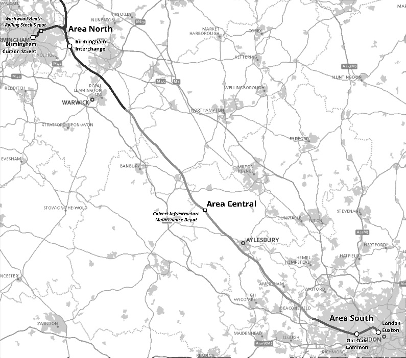
This paper focuses on the southern section of High Speed Two (HS2) Phase One – Lots S1 and S2 (Area South) – which includes the Northolt Tunnels and the Euston Tunnel and Approaches, being delivered by the SCS Integrated Project Team.
The Main Works Civil Contracts for Area South took the design of the ventilation shafts in the Euston and Northolt tunnels though a journey of holistic design development. From the preliminary designs of these assets developed by HS2 Ltd to a final design that fulfilled the complex requirements for these assets during both construction and operation stages.
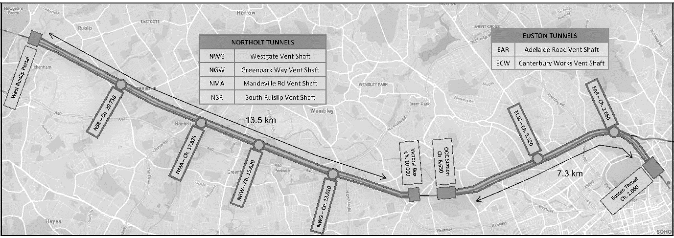
The HS2 tunnels require ventilation and intervention shafts approximately every 3km. The scheme for the Area South section includes six ventilation and intervention shafts, two shafts in the Euston Tunnels and four shafts in the Northolt Tunnels (Figure 1 and Figure 2).
The shafts and associated headhouses provide space for fans and related electromechanical equipment necessary to manage smoke in the event of a fire. They also accommodate additional railway systems equipment required for the operation of the high-speed trains.
The shafts provide dedicated and continuously available intervention point access for emergency services to respond to an incident, such as a fire in the tunnels. Both Euston and Northolt tunnels comprise twin bore segmentally lined tunnels. These two running tunnels, upline and downline, are connected by cross passages that provide evacuation to the other tunnel in case of an incident in one of the tunnels.
The tunnels are bored through the typical London geology that also determines the geology for the excavation of the shafts. London Clay prevails in the eastern section. The whole length of the Euston Tunnels and the first section of the Northolt Tunnels are completely bored in London Clay. Therefore, Adelaide Road, Canterbury Works and Westgate shafts are completely sunk in London Clay.
The western section of the Northolt Tunnels faces the lower strata in London’s geology. Therefore, the excavation of Greenpark Way, Mandeville and South Ruislip shafts goes through the Harwich Formation, Lambeth Group and related features (Upnor Formation, sand lens…) in addition to the London Clay. Furthermore, the bottom of these excavations reaches the Chalk formation that creates potential bottom instability.
These ground conditions present further challenges for using open face excavations (SCL method) in the construction of the tunnels shaft passages and the shafts. Excavation in water-bearing strata with high permeability requires extensive measures to manage the groundwater and to ensure the stability of the excavation.
Preliminary Design
The number and location of the ventilation and intervention shafts were determined during the hybrid Bill process. The starting point of the Main Works Civil Contractor involvement was the preliminary design of the scheme developed by HS2.
The preliminary design of the shafts satisfied the physical constraints of the different locations and the functional requirements for intervention access and rail systems, including tunnel ventilation.
In terms of physical constraints driving the preliminary design, the following can be highlighted:
- Adelaide Road and Canterbury Works shafts in the Euston Tunnels are located in dense urban areas. The Adelaide Road shaft is located in the slope of a Network Rail cutting in central London; the top of the slope faces a busy road in the London Borough of Camden.
- The shafts in the Northolt Tunnels are located in lower density areas, with semi-industrial surroundings.
- The Northolt Tunnels run below the existing Network Rail and Central Line corridor towards West Ruislip. The HS2 downline tunnel runs just below Network Rail tracks at the shaft locations, therefore, only the upline tunnel is reachable vertically without affecting the existing Network Rail tracks.
- The tunnelling strategy for the Northolt Tunnels considered the use of four TBMs; two of them tunnelling from West Ruislip towards the East and two of them tunnelling from Victoria Road Crossover Box towards the West. The four TBMs are to be extracted at Greenpark Way shaft.
In terms of functional requirements, the design of the tunnel ventilation system was one of the main drivers for the design of the shafts. The main requirements related to the ventilation can be summarised as follows:
- To provide three (3) ventilation fans per shaft, in order to allow for two (2) fans on duty and one (1) spare fan.
- The airflow is variable per shaft according to the ventilation strategy; the airflow determines the area of the airpath connecting to each tunnel in order to achieve a mean air velocity of circa 8 m/s.
| Tunnels | Shaft | Airflow (m3/s) | Area of airpath per tunnel (m2) |
|---|---|---|---|
|
Euston |
Adelaide Road |
280 |
32 |
|
Euston |
Canterbury Works |
280 |
32 |
|
Northolt |
Westgate |
400 |
50 |
|
Northolt |
Greenpark Way |
260 |
35 |
|
Northolt |
Mandeville Road |
260 |
35 |
|
Northolt |
South Ruislip |
400 |
50 |
The reference design followed a vertical fan approach for all the ventilation shafts. The shafts had to be big enough to allocate three (3) fans inside in addition to providing the route for intervention access and the rest of service connections from the technical rooms in the headhouse to the tunnels.
With the exception of the Adelaide Road shaft, due to its particular site constraints, the reference design developed for all of the shafts a rectangular shape. The rectangular layout for a shaft is optimal in terms of the use of space for functional purposes but constrains the construction methodology to the use of diaphragm walls or similar (piles) and requires propping during the excavation of the shaft.
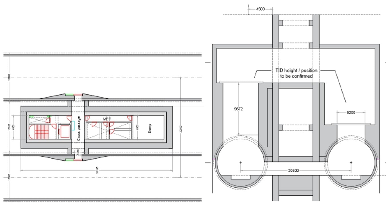
In the case of South Ruislip, Mandeville Road and Westgate shafts in the Northolt Tunnels, the preliminary design was a rectangular shaft encompassing the upline tunnel with adit connections for ventilation and intervention to the downline tunnel. This design solution was a consequence of the presence of the Network Rail tracks over the downline tunnel that precluded the vertical access to this tunnel (Figure 3).
Greenpark Way shaft in the Northolt Tunnels had to provide space for the removal of the four TBMs, therefore, the preliminary design considered a rectangular shaft encompassing both the upline and downline tunnels to receive the TBMs. This solution requires the temporary diversion of the existing Network Rail tracks during construction. After the construction of the shaft, the tracks will be placed back into their original location (Figure 4).
The previous arrangements presented were not optimal in terms of ventilation performance due to the unbalanced airpath from the fans to the two tunnels as displayed in the previous figures.
The Canterbury Works shaft in the Euston Tunnels was also designed as a rectangular shaft encompassing both tunnels to allow a symmetrical arrangement of the ventilation fans in relation to the tunnels, maximising the ventilation performance. In this location, no specific constraints precluded vertical access to both tunnels (Figure 5).
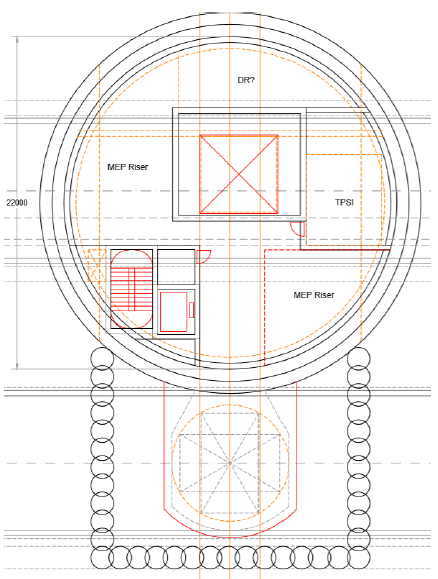
The reference design for the Adelaide Road shaft in the Euston Tunnels provided a different solution for the shaft due to the limited space available in the site selected to build this asset. In this case, the solution was a circular shaft 22m internal diameter encompassing the downline tunnel; the circular shaft allocated three (3) vertical fans as in the other shafts (Figure 6).
The connection to the downline tunnel for ventilation and intervention required the construction of two long adits; the geology (whole shaft in London Clay) facilitated this arrangement.
Stage 1. Scheme Design; Optioneering and design development
Stage 1 of the Main Works Civil Contract included the development of the design for every asset up to a Scheme Design level which would allow moving into Stage 2, to start the Detail Design and the construction of the works.
Stage 1 started with an exercise of value engineering where different design options for each shaft, including the baseline design described in the previous section, were compared in order to select one single option to be developed in the design.
With the early involvement of the Main Works Civil Contractor, this optioneering process captured not only the functional requirements for the shafts but also the main construction drivers in order to select the optimal solution for both construction and operational stages.
Some of the main preferences for the design of the shafts introduced from the point of view of the construction are outlined below:
- The construction programme is driven by the tunnelling activities; shafts designs that allow delinking the construction of the shafts from the tunnelling programme are preferable.
- Circular shape, although not optimal for space use, is much preferred to rectangular shape in terms of construction programme. It does not require propping during excavation of the shaft and provides construction methodology flexibility. Circular shape allows different construction methodologies, from diaphragm wall to SCL, depending on the ground conditions.
- Standardisation of the solutions to improve not only the construction stage by facilitating the development of the design, procurement process, common construction methodologies but also the operational stage, providing a scheme easier to operate and maintain.
Several options were developed in the value engineering process. In absence of further constraints, the above-mentioned preferences led to a solution with a circular shaft in between the tunnels. In this way, the delinking between the construction programme of the tunnels and the shafts is maximised.
This option was explored among other solutions for all the shafts. Placing a circular shaft between the tunnels, big enough to fit three vertical fans led to a significant impact to the alignment, increasing the separation between tunnels in a long section and therefore increasing the length of the cross passages between the tunnels.
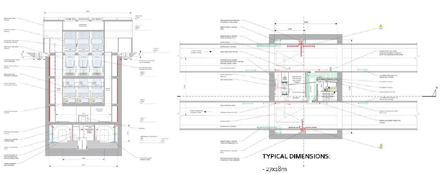
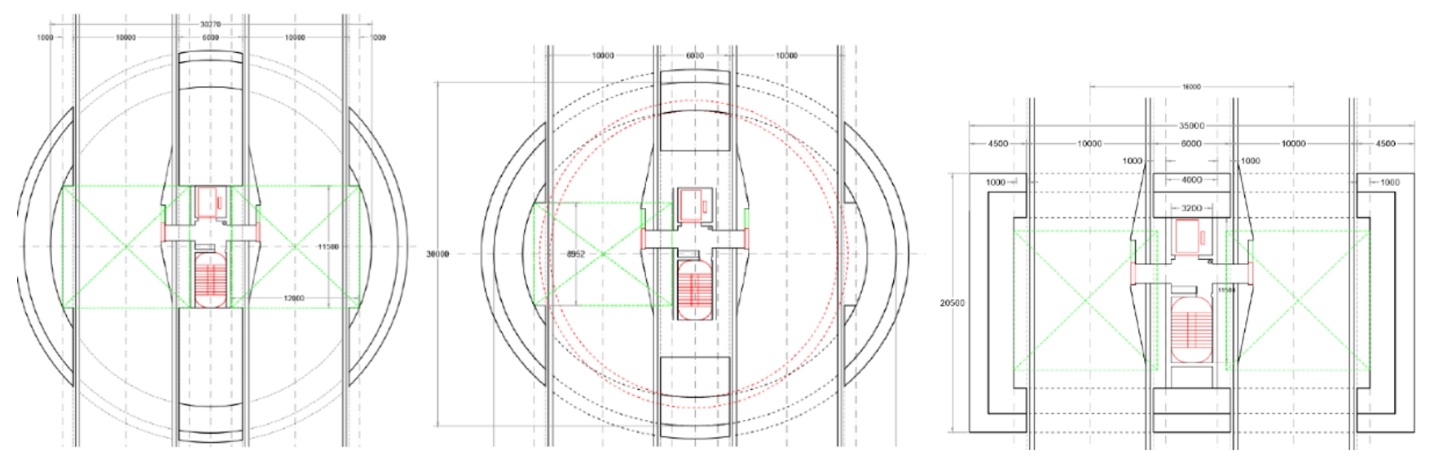
A couple of options were developed to fit a smaller shaft between the tunnels to reduce the impact to the horizontal alignment, keeping an enlarged section above to host the vertical fans, as shown in Figure 7.
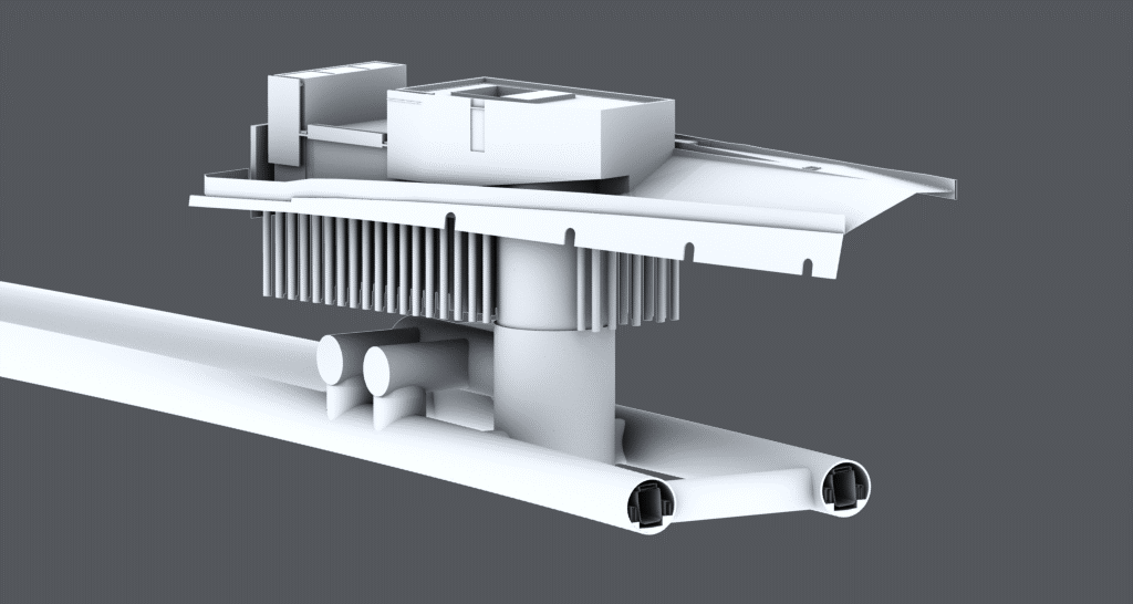
One of the options proposed to move the fans out of the shaft into the headhouse and place them in a horizontal arrangement. This way, the shaft could be reduced to the minimum diameter to provide the stairs and lift for intervention, the risers for services connectivity and the vertical airpath connecting the fans on surface with the tunnels.
The diameter of the shaft could be reduced up to circa 15m; minimising the excavation, traffic for soil removal and accelerating the construction programme. See Figure 8.
The circular shaft between the tunnels with horizontal fans achieved the highest degree of delinking between the shaft and tunnel construction programme. The interface is limited to the openings for intervention, service connection and ventilation.
Although the impact to horizontal alignment is reduced with the small shaft with horizontal fans, an increase of the distance between the tunnels is still required.
The circular shaft with horizontal fans was assessed as the best solution and therefore the single selected option for the two shafts located in the Euston Tunnels, Adelaide Road and Canterbury Works shafts. The key aspects for this decision were:
- These two shafts are located in the Euston Tunnels, close to Euston Station where the design speed of the line is low and there is flexibility in the horizontal alignment to increase the distance between tunnels locally, without a major impact to the cross passage length and without clashing with any obstruction.
- Tunnels and shafts are completely excavated in London Clay; the TBMs do not require specific inspection as the geology is not very demanding in terms of cutter wear and there is flexibility to explore different arrangement for the ventilation adits connecting to the tunnels.
The selected solution presented a challenge in terms of the architectural integration of a larger headhouse required to host the horizontal fans. However, the perceived benefits include construction cost, carbon reduction, improved maintenance access having less equipment in the shaft, improved off site manufacturing opportunities and overall, less materials required.
In the shafts located in the Northolt Tunnels, several aspects prevented the selection of the same solution as for the Euston Tunnels shafts.
The design speed in Northolt Tunnels is higher and there is less flexibility in the alignment to increase the distance between tunnels without a significant increase of the length of the cross passages. This is especially counterproductive when considering the geology of the western section of Northolt Tunnels, mainly Lambeth Group and Chalk, which is not as favourable for the cross-passage construction as the London Clay.
In addition to the above, the presence of a piled building close to Greenpark Way shaft limited any possible movement of the tunnels northwards to avoid clashing with the obstruction.
During the optioneering process, the tunnelling strategy for the Northolt Tunnels was revisited. The eastern section of the Northolt Tunnels, in London Clay, will be excavated using SCL techniques and only the western section will be excavated with TBMs launched from West Ruislip portal towards the east. This way, only two (2) TMBs were required for the construction of Northolt tunnels. The TBMs were no longer extracted in Greenpark Way shaft but they were received in an underground cavern between Greenpark Way and Westgate shafts.
The design of Westgate shaft had to allow for the launch of SCL tunnels according to the revisited tunnelling strategy. A shaft between the tunnels was not compatible with this requirement therefore this option was discarded for Westgate, although the ground conditions (whole shaft in London Clay) and flexibility in the alignment were favourable for this option.
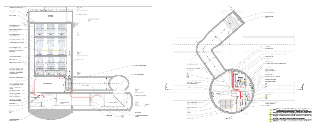
The single selected option for the ventilation shafts in the Northolt Tunnels was a circular shaft with a 25m diameter encompassing the upline tunnel with connection to the downline tunnel in a lateral adit to avoid affecting the Network Rail corridor running on top of the downline, as shown in Figure 9.
This solution links the shaft and tunnel construction programmes as the tunnels drive through the shaft and adit, which have to be ready to receive the TBMs. However, significant benefits were still achieved compared to the preliminary design.
This solution reduced excavation material by 20%, concrete quantities by 37% and carbon by 45% compared to the preliminary design, providing cost, programme and environmental benefits. In the case of Greenpark Way shaft, where the preliminary design considered an even bigger rectangular shaft to extract the TBMs, the benefits were maximised.
The crossing strategy for the downline TBM was to fill the lateral adit with foam concrete in order to:
- create a safe area for intervention of the TBM (maintenance of cutter head and shield tail in atmospheric conditions),
- and provide a safe area to build the lateral connection for ventilation and intervention.
The shaft encompassing the upline tunnel with the downline tunnel crossing the lateral adit allowed achieving the challenging cross section area for ventilation connecting to the tunnels. In South Ruislip and Westgate shafts, the ventilation strategy required 50m2 connecting to the tunnels compared to only 32m2 required in the shafts in the Euston Tunnels.
Design Development
The single selected option was developed up to a scheme design level in order to build a robust construction programme and cost estimation for the scheme, and progress engagement with stakeholders.
During the development of the scheme design, the tunnelling strategy for the Northolt Tunnels reverted to the original strategy with four TBMs and Greenpark Way shaft as extraction point.
It was assessed that the single selected option for Greenpark Way shaft permitted the extraction of the four TBMs. The downline TBMs will be received in the lateral adit and dismantled laterally to the main shaft for their lifting. In this way, the Network Rail tracks running on top remain unaffected, improving the programme and interfaces.
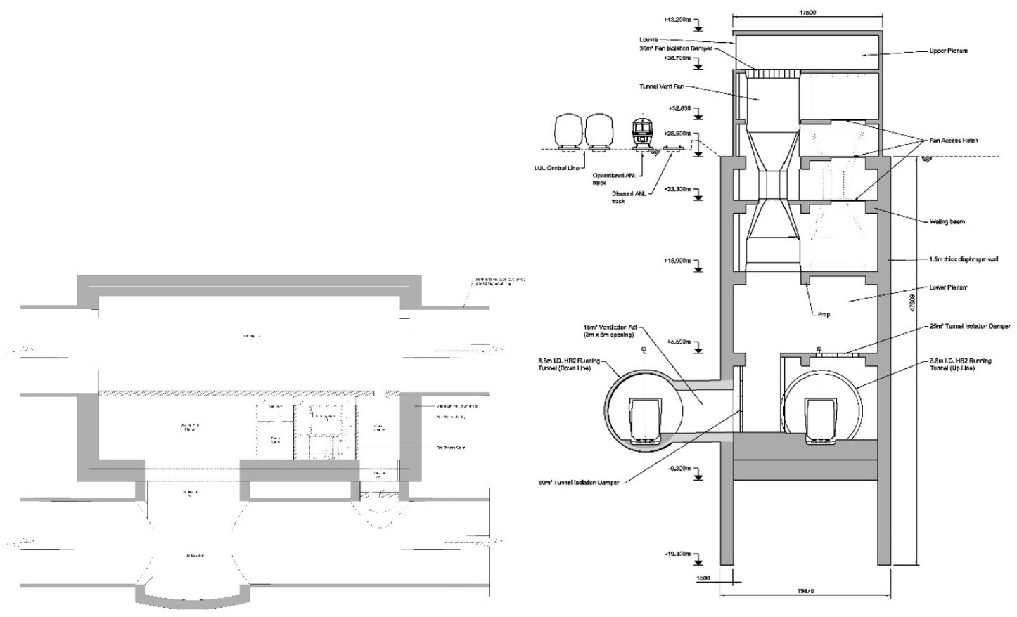
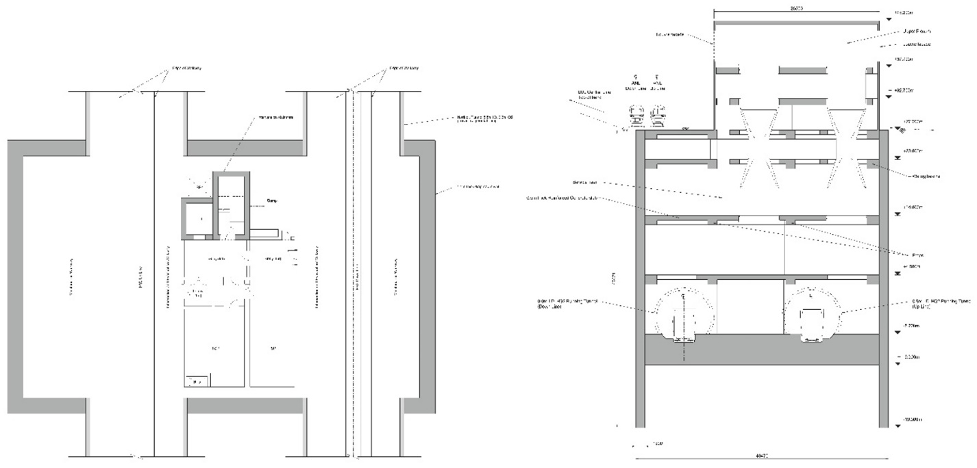
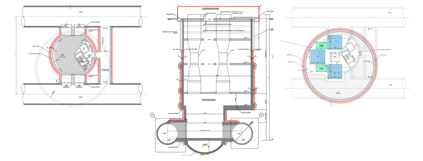
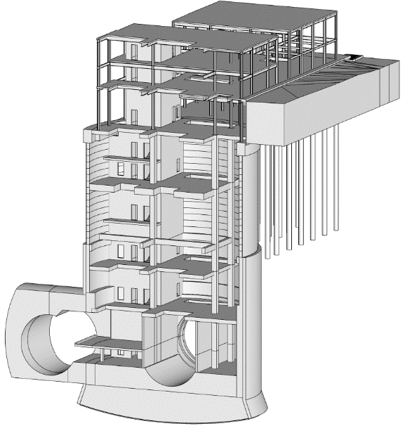
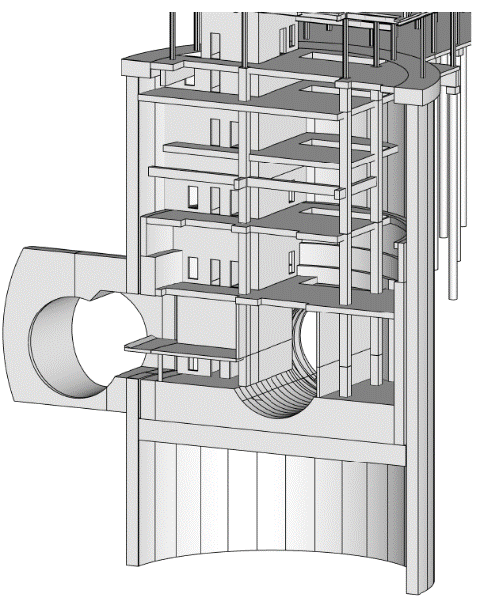
Precast segments rings in the upper part of the shaft and SCL plus cast in situ secondary lining in the lower part to perform the openings were the selected construction methodologies for all the shafts in the Northolt and Euston tunnels, with the exception of South Ruislip shaft. In this case, the proximity of the shaft base slab to the Chalk and the concerns for the management of the groundwater during construction moved the selection to Diaphragm walls. See Figure 10 and Figure 11.
The use of precast elements was preferable in order to maximise the off-site construction, with an optimal use of the materials reducing traffic and carbon footprint.
The adit connection to downline presented a technical challenge; the adit span reached 17m to allow the crossing of a 10 m diameter TBM.
In the western shafts (South Ruislip, Mandeville Road and Greenpark Way shafts) the adit was located in the Harwich Formation and in the Lambeth Group, where some sand lens had been identified. Extensive groundwater mitigation measures were anticipated to build this adit using SCL method, including the use of a combined approach of permeation and fissure grouting, and depressurisation and dewatering.
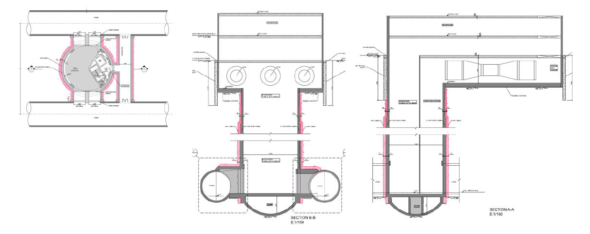
The design of the Euston Tunnels shafts with horizontal fans evolved. A top connection to the tunnels for ventilation was preferred in order to facilitate the connection. The London Clay facilitates the construction of SCL adits, therefore a ventilation adit with top connection to the tunnels was included in the scheme (Figure 12).
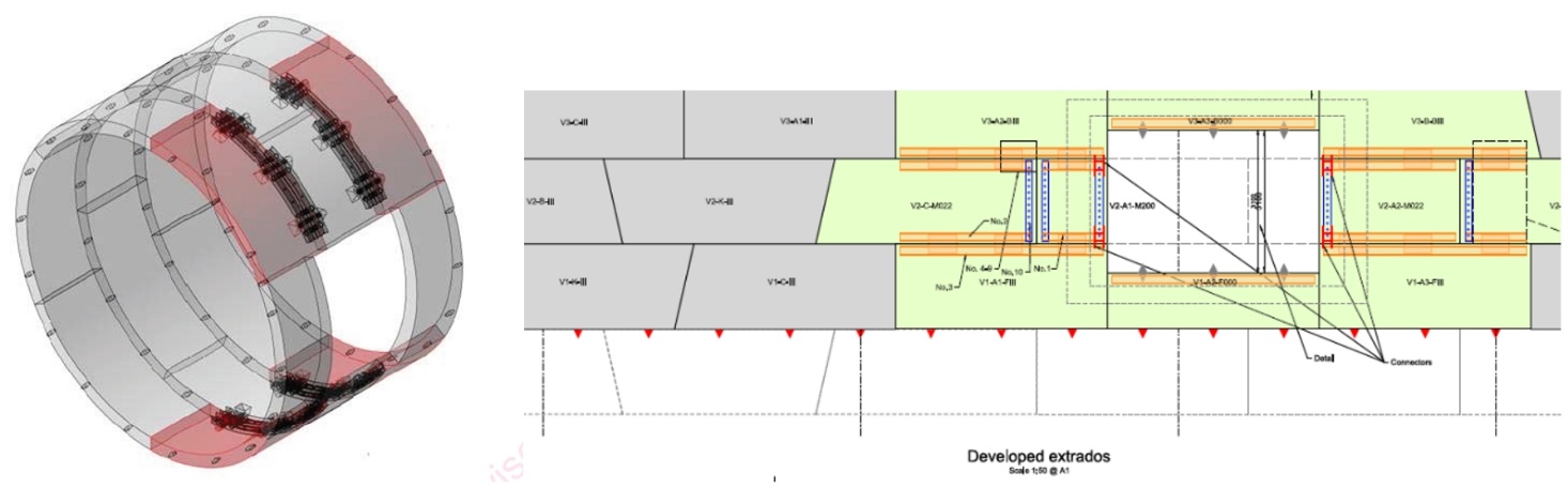
All the openings in the segmental lining of the tunnels, connecting the tunnels and the shafts for intervention and ventilation, were developed with the use of special segments. The design approach was to provide special rings that allow the disassembly of part of the segments without temporary support because the loads are transferred to the adjacent rings (example in Figure 13).
This strategy, although it constrains the feasible opening to the structural resistance of the segmental lining, accelerates the construction and improves the safety of the construction by reducing the temporary works required.
An external consultant reviewed the scheme design for the six ventilation shafts to provide the required Cat 3 check; the scheme was accepted and signed off with a level 3 certificate; and it was ready to be developed into Detail Design in Stage 2.
Stage 1. Scheme Design Update. Further Value Engineering
Before moving into Stage 2, HS2 together with all Main Work Civil Contractors undertook a review of the scheme to identify further optimisations and programme savings. Two main aspects affected the design of the shafts, in particular the shafts in the Northolt tunnels:
- Implementation of an accelerated TBM programme at West Ruislip portal, caused by the shortening of the portal and improved TBM-logistics construction programme. This acceleration allowed launching the TBMs from West Ruislip ten (10) months in advance, putting South Ruislip shaft construction on the critical path.
- The ventilation strategy for the Euston and Northolt tunnels was revisited by HS2. The ventilation requirements at the shafts, in terms of number of fans, airflow and airpath areas, were significantly reduced. HS2 also expressed a preference for the horizontal fan arrangement that had been implemented in Euston Tunnels shafts; it had been proven that removing the fans from the shaft highly improved carbon footprint and reduced programme.
The airflow required at all shafts was reduced to 200 m3/s. As a consequence, the required cross-sectional air path was also reduced to 25m2. With reduced airflow, the number of fans could also be reduced to two, allowing one fan on duty and one spare when working at full capacity.
| Tunnels | Shaft | Airflow (m3/s) | Area of airpath per tunnel (m2) |
|---|---|---|---|
|
Euston |
Adelaide Road |
200 |
25 |
|
Euston |
Canterbury Works |
200 |
25 |
|
Northolt |
Westgate |
200 |
25 |
|
Northolt |
Greenpark Way |
200 |
25 |
|
Northolt |
Mandeville Road |
200 |
25 |
|
Northolt |
South Ruislip |
200 |
25 |
The reduced airways connecting the tunnels opened a door to study a reduction in shaft dimensions at the Northolt tunnels shafts.
Westgate, Canterbury Works and Adelaide Road shaft
Westgate shaft is located in an area where the ground conditions are similar to those in Euston tunnels, mainly comprised of London Clay. This shaft was originally planned for the launch of SCL drives both eastwards and westwards and to provide 50m2 connecting to the tunnels for ventilation.
The tunnelling strategy reverted to the use of four TBMs and the reduction of the ventilation requirements enabled Westgate typology to be switched over to the Euston type shaft, with the smaller 15m diameter PCS rings shaft in between tunnels and the same SCL ventilation adit connecting to the top of the tunnels in London Clay.
A feasibility analysis was developed to analyse the change of Westgate shaft, assessing the impact to the alignment and to the integration of the headhouse in the land available. It was confirmed that Westgate shaft is located in a section with enough flexibility in the horizontal alignment to increase the separation of the tunnels and fit the shaft in between, without affecting the Network Rail tracks.
The change of Westgate shaft to the Euston type solution was accepted. This way, the three shafts that shared similar ground conditions, flexibility on the horizontal alignment and now also the same ventilation requirements, ended up with the same functional solution that maximised the main benefits of the value engineering exercise: programme delinking, optimal use of materials to reduce carbon footprint and standardisation.
A Scheme Design Update was developed and completed for Adelaide Road, Canterbury Works (Figure 14), and Westgate shafts, considering the new ventilation requirements. This scheme is progressed in Stage 2 into Detail Design and construction.
South Ruislip, Mandeville and Greenpark Way Shafts
The accelerated programme at West Ruislip portal with the earlier launch of the TBMs put pressure on the design and construction programme of the shafts on the western section of Northolt tunnels, especially to South Ruislip. It was clear that improving the TBM and shaft construction interface would minimise programme risks.
A value engineering exercise was undertaken to improve this interface, by applying the reduced ventilation requirements and other changes in the requirements.
For instance, the requirement of having the tunnels at least one diameter apart was relaxed allowing the tunnels to be closer together. The change of this requirement opened the door for a new set of possible shaft configurations, as it was possible now to pull out the downline tunnel from under Network Rail tracks. This was an important driver for exploring options where the distance between the tunnels could be reduced to the absolute minimum, shifting the downline tunnel as far north as possible.
Several options were developed for South Ruislip and Mandeville Road Shafts in this exercise. The different options followed two different approaches: placing a shaft in between the tunnels and solutions enclosing the area connecting to downline tunnel.
The first type of options looked for placing a small shaft between the tunnels, considering the reduced area connecting to the tunnels for ventilation would facilitate the adit construction in difficult ground conditions. These solutions seek maximum delinking between the tunnels and the shaft. Example shown in Figure 15.
Another option was the evolution of the previous solution but considering horizontal fans, changes in the alignment that allowed vertical access to the downline tunnel and the reduced ventilation connection to the tunnel.
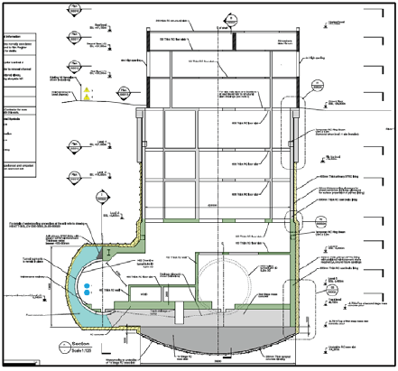
A smaller shaft option was developed reducing underground works and reducing carbon footprint (Figure 16). The connection to the downline was done in an enclosed area, reducing construction and programme risks.
At Greenpark shaft the design could follow the general principles of the other shafts, but the need to extract the four TBMs at this location within a very short timeframe meant that a different solution had to be considered.
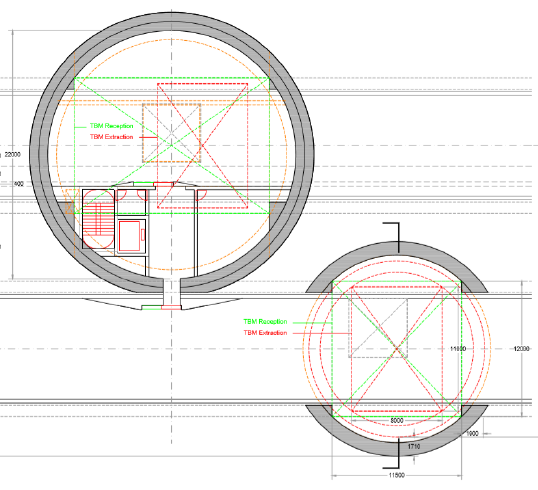
Several options were explored for Greenpark Way shaft where both tunnels were brought together as close as possible and they were encompassed by a single shaft, without affecting Network Rail tracks. This solution facilitated the TBM extraction by having only vertical lifting (see Figure 17).
A rectangular shaft offered the most efficient use of space and minimised excavation. On the other hand, it required diaphragm walls and the structure was less efficient than other options with circular or elliptical geometries, requiring up to 2m wide diaphragm walls and important propping elements that complicated the internal arrangement.
Circular options were explored but the spatial requirements for TBM reception and extraction led to shafts of up to 37m in diameter. Caterpillar shaped shafts did not allow for construction other than with diaphragm walls and still required propping during construction.
All these options faced two major challenges. An encompassing shaft always led to a very large excavation volume with high carbon footprint impact and considerable construction times. The second problem was that the depth and dimensions of the shaft would mean a challenge for the groundwater management during construction.
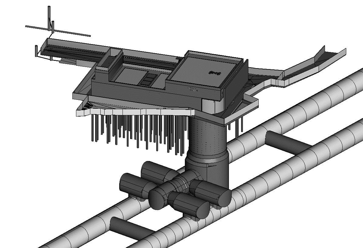
These challenges led to explore one final option, the satellite solution. In this scheme, the upline connection kept the previous solution with the tunnel running through the shaft and the TBM extraction for the downline tunnels was solved with a secondary smaller shaft that also permitted to achieve the connection for ventilation.
The resulting two smaller shafts reduced the excavated volume by close to 50% and the construction programme by up to almost a year. Groundwater management during construction and uplift issues were also mitigated greatly. See Figure 18.
This design then fed back into the South Ruislip and Mandeville Road shafts, where it was confirmed that the satellite solution would also benefit construction and programme.
At South Ruislip shaft, the satellite shaft provided a safe area for the inspection and maintenance of the downline TBM cutter-head in atmospheric conditions. In the case of Mandeville shaft, the inspection of the TBMs was not required. Therefore, the satellite shaft was only used to achieve the ventilation connection and a reduced diameter could be used.
The satellite option was selected as preferred option in the sifting process for Greenpark Way, Mandeville Road and South Ruislip ventilation shafts. This solution took on board the updated ventilation requirements and provided an optimal solution that achieved the target of reducing construction risks, improving the interface between the tunnels and the shafts at the three locations.
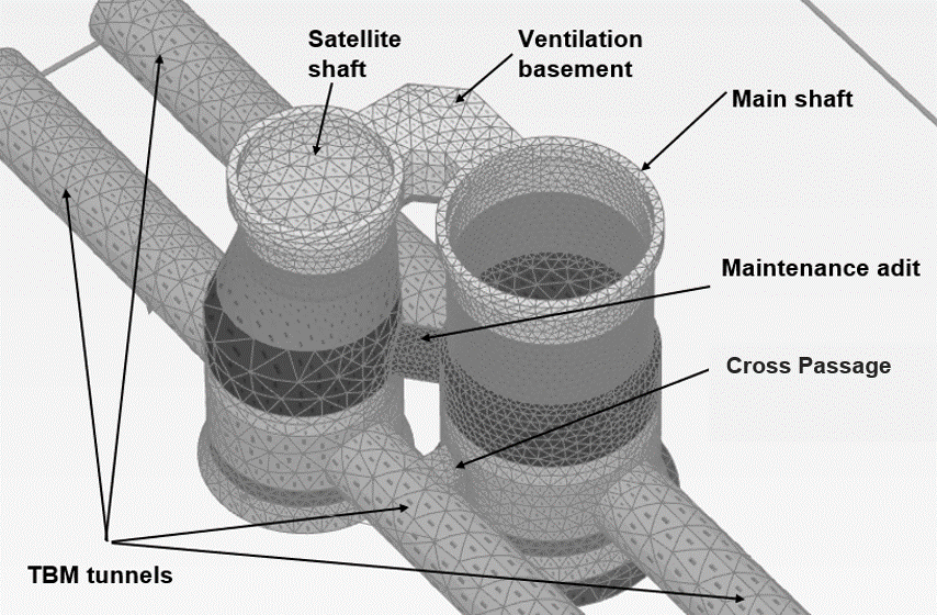
The satellite option was developed at a Scheme Design level to become the Stage 1 proposal for Greenpark Way, Mandeville Road and South Ruislip ventilation shafts. This is the scheme being developed to detailed design and construction in Stage 2 (Figure 19).
Conclusions
This paper describes the design journey for the six ventilation shafts in the section south of the HS2 Phase One in the Euston and Northolt tunnels and shows how the final design is a balance of different requirements and preferences covering both construction and operational stages.
Once all the requirements and constraints are understood and analysed together, the selected solutions are optimal in terms of functional performance, carbon footprint and construction programme and cost. The robust processes to assess the different options provide sufficient confidence in the solutions being progressed in Stage 2 to provide a reliable solution for the HS2 infrastructure.
The early participation of the Main Works Civil Contractor in the design stages and working side by side with HS2, have allowed development of a robust solution satisfying the necessary requirements and constraints.
The six ventilations shafts have been solved with only two different functional solutions, driven mainly by the ground conditions, the alignment flexibility and the interfaces with third parties, in addition to the ventilation requirements and TBM interface.
In terms of the headhouses, the horizontal fans configuration for all shafts means that the design has a standardised approach, sharing a common design, optimising procurement and construction processes.
Peer review
- Colin Rawlings, Lead Tunnel EngineerHS2 Ltd