Advances in Engineering Survey Grid Transformations for Rail Infrastructure
This paper provides a summary of innovative approaches developed on Snake Projection coordinate transformations that maximise data interoperability and compatibility within CAD, GIS and survey software and systems.
The project’s topographical survey, design and construction use an engineering coordinate system defined by the HS2 Snake Projection together with the HS2 Vertical Reference Frame. This approach has several advantages including minimal scale factor and height distortion at track level [1] with seamless continuity over the project.
For HS2, the zero-order survey control is defined by the Ordnance Survey OS Net™ network of Continually Operating GNSS Reference Stations (CORS). In 2016, Ordnance Survey updated the geodetic coordinates of OS Net [2] and the implications of these changes on HS2’s track design are potentially significant. For example, the update caused a 13mm horizontal shift and 25-30mm vertical shift in engineering coordinates. To ensure the project achieves positional stability and thus remains unaffected by these changes, both now and into the future, a description is presented of the development of a new geodetic transformation called HS2TN15 and a new equipotential geoid model, HS2GM15, which are applicable respectively to plan and height coordinates.
The HS2 Survey Grid transformations enable highest accuracy engineering survey for the project design, construction and operation; fully validated and authoritative for use, with significant benefits realised to date. HS2 has led knowledge sharing sessions with the wider industry, with the revised Snake Projection methodology being increasingly adopted on further infrastructure projects.
- Written by
-
James Turner (HS2 Ltd/HS2 Ltd)

-
Peter Swales (HS2 Ltd/CADBadger Ltd)

-
Jamie Finney (HS2 Ltd/HS2 Ltd)

- Resource type
- Resource type: Technical Paper
- Tags
- CAD posts
- Coordinates posts
- Geodesy posts
- GIS posts
- Height posts
- HS2 Survey Grid posts
- railway systems posts
- Scale Factor posts
- Snake Projection posts
- Topographical Survey posts
- Track Engineering posts
Background
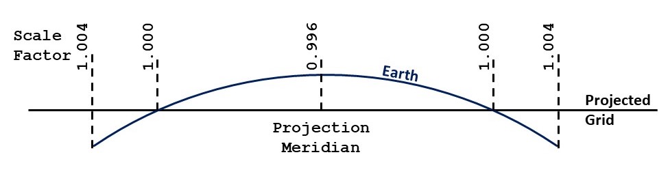
One of the fundamental issues of survey engineering is how best to represent the curved surface of the Earth onto a flat plane without introducing distortion of some kind. An example is illustrated in Figure 1, where the scale factor represents the errors in distance measurements within the projected grid. The Snake Projection solves this. It is a relatively new innovation in planar engineering grids that was developed through a collaboration between Network Rail and University College London [3]. When tailored to a specific project the Snake Projection delivers a seamless coordinate system. It is typically used on long linear infrastructure works, and effectively operates as a true-scale site grid that is valid for the entire length of the route.
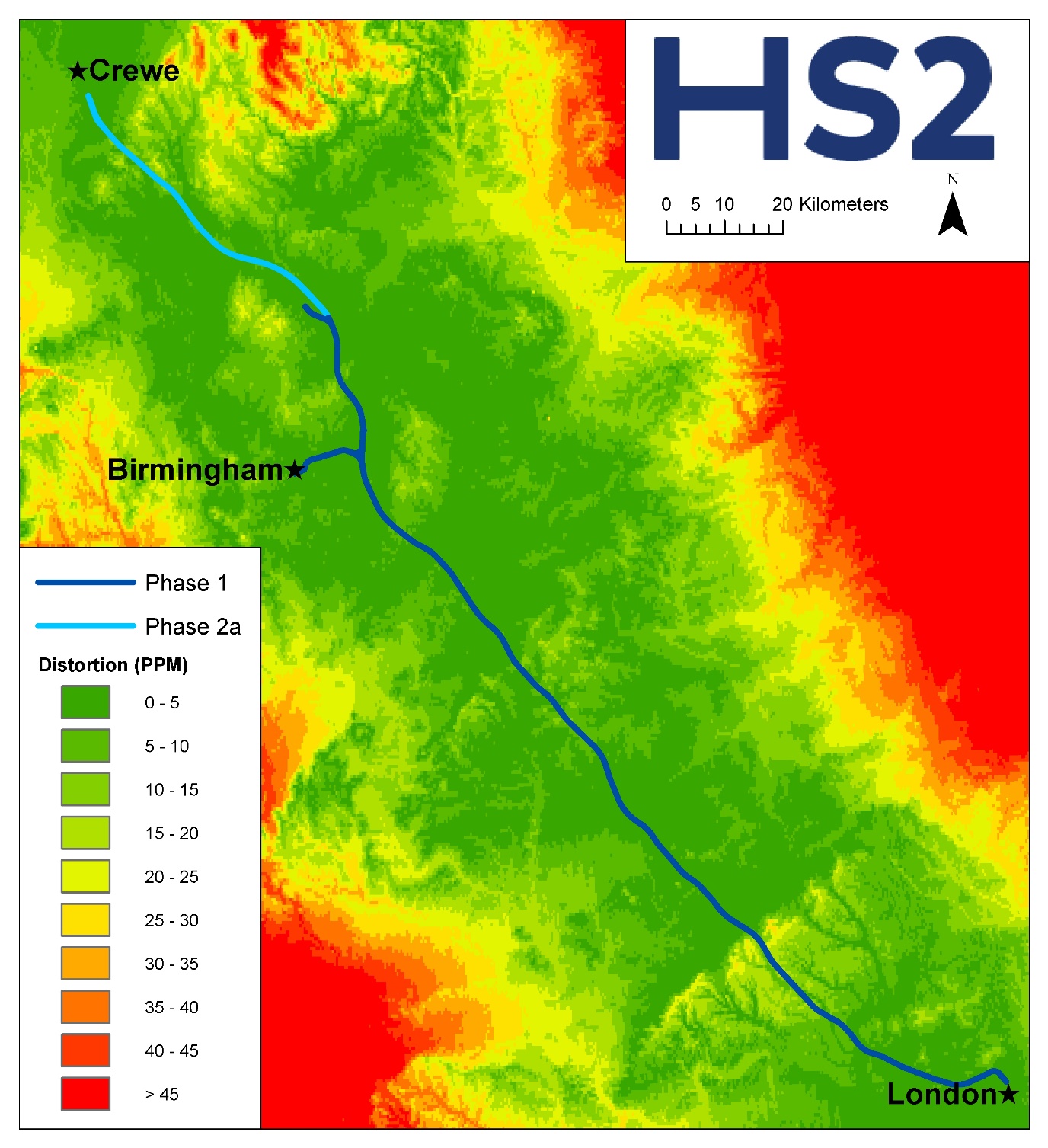
The HS2 Snake Projection applies to both Phase One between London and the West Midlands and Phase 2a to Crewe. It features scale factor distortion of under 20 PPM throughout, which equates to a distance distortion less than 2 cm per km (a map of distortion at ground level is seen in Figure 2).
To demonstrate the reasons for using the HS2 Snake Projection, imagine a line approximating the route from London to Birmingham. Measuring the line first in British National Grid, and then measuring again in HS2 Snake Projection would reveal an apparent increase in length of 60 metres. In fact, the length of the project on the ground did not change – it is just that the British National Grid is a best-fit for the whole country which means the map distortion is far in excess of what is appropriate for precision engineering required on projects like HS2. Consequently, the HS2 Snake Projection is the horizontal coordinate system used for project design and construction.
In the vertical dimension, engineering levels have been measured with respect to Ordnance Datum Newlyn (ODN), the national height reference. Together with Eastings and Northings in the HS2 Snake Projection, project engineers use a compound coordinate system commonly termed HS2 Survey Grid.
The HS2 Snake Projection – A Revised Implementation
Since the development of the Snake Projection methodology, the advantages have been readily apparent to the extent that it is now being used throughout the UK rail industry. The fundamental task of its algorithm is to convert between geodetic coordinates and grid coordinates. However, the projection algorithms and parameters are so new as to be unsupported by the majority of spatially enabled software and systems, including CAD and GIS. Furthermore, the methodology was not viable for inclusion in the European Petroleum Survey Group global coordinate system registry [4], which is the authoritative source of geodetic definitions used by AEC software providers.
The situation mirrors a similar scenario faced several years ago by Ordnance Survey when it was defining the British National Grid using the OSTN02 transformation [5]. The native ‘Grid Inquest’ OSTN02 was not directly compatible with a variety of software packages therefore it was released in a second format, this time using a standard grid shift file for geodetic transformations called ‘National Transformation version 2’ (NTv2; [6]).
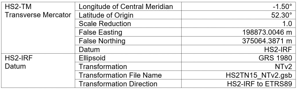
Inspired by Ordnance Survey’s approach, HS2 Ltd conducted a proof-of-concept study to research and validate an alternative implementation for the HS2 Snake Projection which was based upon existing standards. This emulation of the authoritative methodology was implemented by the creation of a new Transverse Mercator projection (HS2-TM) and intermediate reference frame (HS2-IRF) accompanied by a new NTv2 transformation comprising a grid of shift values to transform between ETRS89 and the HS2-IRF (Table 1).
The study was a success – the HS2 NTv2 process was verified via desktop study at over 348,000 locations project-wide and featured virtually identical agreement with the authoritative Snake Projection method (RMS difference was negligible at 0.2 mm).
Single Source of Truth
The impact of the HS2 NTv2 revision was significant. The coordinate system became immediately compatible with virtually all spatially enabled platforms, in particular CAD and GIS. The first benefit was allowing the reprojection of design data to and from the HS2 grid to be undertaken in-situ, which is especially useful for CAD files which will now retain complex geometry.
Perhaps the most significant benefit is the use of reprojection ‘on the fly’ which facilitates the single source of truth. Previously the same piece of geospatial information may have been stored in multiple data containers; one for each of the coordinate systems required, which resulted in significant issues with data conversion and data management. Now a single version of data requires maintenance, and when the geometrical representation is required in an alternate coordinate system the reprojection can be performed automatically within software.
HS2 has undertaken a study with TfL to investigate the benefits of data coordination using the ‘on the fly’ reprojection method that is now available. On the back of this study HS2 and TfL agreed a concession against the requirement to deliver data for coordination and at handover to TfL in their LSG grid. Benefits to the project included:
Risk reduction – removing the requirement of translating AEC data between HS2 Snake Projection and TfL LSG grid resulted in minimisation of the risk from added translation inaccuracies. The new process also removes risk due to data recipients no longer having to take ownership of data through their translation process.
Design coordination – the coordination between HS2 and TfL is smooth and immediate without the need to translate the data each time information is issued.
Resources – by adopting a streamlined process there is scope for efficiency savings by removing the requirement of coordinating with TfL standards and grids as well as with HS2 standards and grids. Over the life of the project, resultant cost savings have the potential to be significant.
As demonstrated, the tangible benefits for data currency, data management and efficiency are significant. HS2 are now working with other interfaces to realise the same benefits as with TFL, to again reduce risk and cost.
CORS OS Net Update 2016
In Great Britain, Ordnance Survey operates OS Net – a CORS network of stations that operate as the national reference for Global Navigation Satellite Systems (GNSS) survey. In 2016 the geodetic ETRS89 coordinates of the stations were recomputed from OS Net v2001 to OS Net v2009 causing a horizontal shift in coordinates [2]. To minimise the impact on National Grid coordinates Ordnance Survey released a new transformation, OSTN15. As a result, National Grid coordinates are achieved through OS Net v2009 + OSTN15, with the aim of equivalence to those achieved through OS Net v2001 + OSTN02.
At the same time Ordnance Survey released an updated geoid model (or more correctly a “height corrector surface” since a gravimetric geoid surface has been fitted to the local mean sea level based datums) for use with the revised OS Net. OSGM15 transforms ellipsoidal heights into orthometric levels above Ordnance Datum Newlyn (ODN). In this case the updated transformation did not achieve equivalence, with a 25mm step in measured levels compared to those achieved before the 2016 update with OSGM02. Effectively the datum point for height measurement was systematically lowered, resulting in ODN heights increasing by approximately 25mm nationwide.
HS2 Horizontal Transformations – HS2TN02 and HS2TN15
The underlying datum for the HS2 Snake Projection is the same as for the British National Grid: ETRS89 as realised by the OS Net CORS network. Consequently, HS2 engineering coordinates were subject to the same horizontal shift when the OS Net was recomputed in 2016. For an engineering coordinate system implemented for precision and accuracy this is not insignificant and has the potential to introduce spatial misalignment exceeding accuracy tolerances for construction of the permanent way.
In this situation the Ordnance Survey approach was the inspiration once more. Following the OS transformation naming convention, the legacy process for determining HS2 coordinates became known as HS2TN02. The revised implementation of the HS2 Snake Projection suddenly acquired a further benefit because the flexibility of the NTv2 format enabled HS2 to effectively maintain positional stability of grid coordinates. This was accomplished by the computation of a new geodetic transformation, HS2TN15, valid for acquiring HS2 grid coordinates using the updated version of the OS Net.
Now, HS2 Snake Projection coordinates achieved through OS Net v2009 + HS2TN15 are virtually equivalent to those achieved through OS Net v2001 + HS2TN02. Thus, the project risk from geodetic change is reduced.
Orthometric Height
In the vertical dimension, HS2 engineering data uses levels referenced to the national height reference Ordnance Datum Newlyn. However, as described above, in 2016 the datum itself was redefined resulting in a vertical shift of approximately 25 mm. In effect, the significant majority of existing survey and design data across the HS2 Project became referenced to a legacy vertical datum.
To prevent ambiguity in the management of engineering data the need for a standardised approach was evident; this would have to be the best available in terms of survey accuracy, consistency with existing data and immunity from any future changes.
The solution was to create the HS2 Vertical Reference Frame (HS2VRF) with the aim being all existing and future project engineering data is on the same height system. To ensure existing data retains currency the HS2VRF is defined to be equivalent to the legacy Ordnance Datum Newlyn realisation 2002. However, in order to retain full survey accuracy there must be a defined relationship to the contemporary OS Net. This necessitated the computation of a new national height corrector surface called the HS2 Geoid Model 2015 (HS2GM15).
Development of HS2GM15
The purpose of the HS2 Geoid Model 2015 is to provide a geodetic transformation such that a GNSS survey conducted using the contemporary OS Net (v2009) can recreate the same ODN levels as if surveying using the previous OS Net (v2001) along with the previous OS geoid model (OSGM02).
The set of control points used for the development of the HS2 Geoid Model 2015 was the 100 Ordnance Survey CORS stations which have geodetic coordinates and orthometric heights available for both OS Net v2001 and OS Net v2009. Using the OSGM02 model as the base surface a correction value could be calculated at each control station, which can be simplified as:
![]() (1)
(1)
Where
![]() is the difference between the ellipsoidal height of station p in OS Net v2009 and the previous orthometric height of station p in ODN02.
is the difference between the ellipsoidal height of station p in OS Net v2009 and the previous orthometric height of station p in ODN02.
![]() is the OSGM02 datum height at station p.
is the OSGM02 datum height at station p.
Least squares collocation is a standard method for interpolating corrections across an equipotential surface [7]. Note that this method accounts for spatial correlation and measurement noise, to produce an optimal solution that does not guarantee ties to control points. To derive the surface correction value u for location i the closest 5 CORS control stations are used in a least squares collocation process:
![]() (2)
(2)
Where
up is the vector of corrections at CORS locations (corrp),
Cip is the vector of covariances between interpolation location i and CORS control point p, and
Cpp is the matrix of covariances between CORS control points.
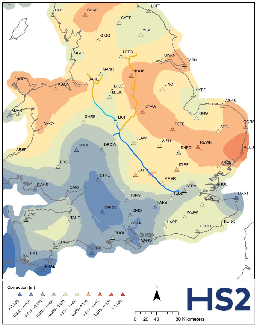
In total across the area of interest there are 2,196,661 correction values computed with minimum value -0.04 m and maximum value +0.06 m; these are plotted in Figure 3. The HS2 Geoid Model 2015 was then able to be calculated by summing the OSGM02 geoid heights with the collocated correction values.
Validation and Verification of the HS2 Geoid Model HS2GM15
The verification process for the HS2VRF was to collate field measurements at a number of locations and process both in legacy (OS Net v2001) and current (OS Net v2009) geodetic datums and transform to HS2VRF orthometric heights using the respective transformation. The overall plan followed:
- Survey GNSS field data (Rinex) at 65 benchmarks (BMs) along the HS2 route.
- Using legacy OS Net CORS – post-process OS Net v2001 geodetic coordinates for each BM.
- Calculate HS2VRF height using OS Net v2001 coordinates and OSGM02 [A]
- Using contemporary OS Net CORS – post-process OS Net v2009 geodetic coordinates for each BM.
- Calculate HS2VRF height using OS Net v2009 coordinates and HS2GM15 [B]
- Validate HS2GM15: Compare height differences between [A] and [B]
The optimal result of the validation process was that the levels achieved through the two methods, [A] and [B], are identical. There were two sets of validation data i.e. the primary set comprised 13 benchmarks that featured a Root Mean Square (RMS) separation in determined levels of 1.3mm, and the 52-strong secondary set featured an RMS separation in levels of 2.5mm.
These differences were deemed minimal, consequently vertical coordinates achieved through OS Net v2009 + HS2GM15 may be said to be virtually equivalent to those achieved through OS Net v2001 + OSGM02.
Summary – The HS2 Transformations
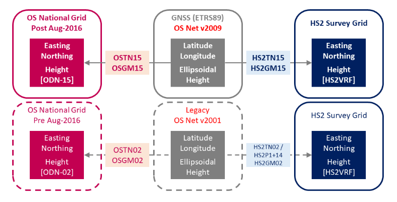
The HS2 transformations and the relationship to GNSS-acquired geodetic coordinates are summarised in Figure 4. To highlight the relationship with National Grid coordinates the OS transformations are also included. Note that the HS2P1+14 Snake parameter file is equivalent to use of HS2TN02 and therefore is to be used alongside the legacy CORS network using OS Net v2001.
When utilising GNSS for HS2 engineering positioning use the contemporary OS Net with the respective coordinate transformations to achieve HS2 engineering positions. At the time of writing the current definition is v2009, therefore the HS2TN15 and HS2GM15 transformations are appropriate.
When converting between OS grid and HS2 grid coordinates always use the same transformation versions. For example, use OSTN02↔HS2TN02 or OSTN15↔HS2TN15.
Conclusions
Three major developments have been described; a new implementation for the Snake Projection which massively increases compatibility, the strategic development of updated transformations for rail engineering grids which follow Ordnance Survey standards, and finally the computation of a new national geoid model to provide consistent levels over the life of the HS2 Project from design to construction and into operation.
All together these provide a basis for coordinate system use, maintenance and stability that is independent of changes to the national control framework and aims to guarantee temporal viability of data holdings as much as possible.
The innovative revisioning of the HS2 Snake Projection to an effective ‘open source’ NTv2 methodology is fully validated and authorised for use. It has massive implications for geospatial data management and manipulation and has provided significant time and efficiency savings to date, including the example quoted. Being equally applicable to further Snake Projections, the development is of great interest within the wider rail and road industry and HS2 Ltd has held knowledge sharing workshops to enable wider exploitation. Projects recently adopting the technology include the Midland Main Line and the upgrade of the A96 from Aberdeen to Inverness.
The current HS2 Snake Projection is valid for Phases One and 2a. Looking to the future, it will be extended to include the grid for Phase 2b to define a single continuous engineering grid featuring unity scale for the whole project that is fully compatible within geospatial systems.
Finally, there is one more positive: through the revised implementation, tailored Snake Projections are now acceptable for inclusion in the global registry of coordinate systems. A whole new wave of EPSG codes is on the way.
Acknowledgements
The services of the Natural Environment Research Council (NERC) British Isles continuous GNSS Facility (BIGF), www.bigf.ac.uk, in providing archived GNSS data (and/or products) to this study, are gratefully acknowledged.
References
[1] RICS (2020) Map Projection Scale-Factor. [Accessed 2020-07-07]
[2] M. Greaves, P. Downie & K. Fitzpatrick (2016) OSGM15 and OSTN15: Updated transformations for UK and Ireland. Geomatics World,
[3] J. C. Iliffe, J. V. Arthur & C. Preston (2007) The Snake Projection: A Customised Grid for Rail Projects, Survey Review, 39:304, 90-99
[4] EPSG (2020) EPSG Geodetic Parameter Registry. [Accessed 2020-07-07]
[5] Ordnance Survey (2002) OSTN02 – NTv2 format. [Accessed 2020-07-07]
[6] Government of Ontario IT Standards (2005) NTv2 (National Transformation Version 2), Document No. 45.2.
[7] J.C. Iliffe, M. K. Ziebart, & J. F. Turner (2007) A New Methodology for Incorporating Tide Gauge Data in Sea Surface Topography Models, Marine Geodesy, 30:4, 271 – 296,
Notation
| Abbreviation | Explanation |
|---|---|
|
AEC |
Architecture, Engineering and Construction |
|
BNG |
British National Grid. Also known as OS National Grid. |
|
CAD |
Computer Aided Design |
|
CORS |
Continually Operating Reference Stations |
|
EPSG |
European Petroleum Survey Group |
|
ETRS89 |
European Terrestrial Reference System 1989 |
|
Geoid |
An equipotential surface defined as being equivalent to mean sea level without the effect of tides and currents; commonly used as the zero-point for orthometric heights. |
|
GIS |
Geographical Information Systems |
|
GNSS |
Global Navigation Satellite Systems |
|
Height Distortion |
The distance between two points increases with elevation, thus introducing a height component into the scale factor distortion. |
|
HS2GM02 |
HS2 height correction surface for the conversion of ellipsoidal heights derived from GNSS to HS2VRF. HS2GM02 preceded HS2GM15 and is used for data captured using OS Net v2001 only. |
|
HS2GM15 |
HS2 height correction surface for the conversion of ellipsoidal heights derived from GNSS to HS2VRF. HS2GM15 superseded HS2GM02 and is used for data captured using OS Net v2009 only. |
|
HS2P1+14 |
The HS2 SnakeGrid™ to be used for engineering design from Euston to Wimboldsley (north of Crewe). The HS2P1+14 parameter file is equivalent to HS2TN02. |
|
HS2TN02 |
HS2 Survey Grid transformation to convert between ETRS89 (latitude and longitude) OS Net v2001 values and HS2 SnakeGrid. HS2TN02 preceded HS2TN15 and is used for data captured using OS Net v2001 only. |
|
HS2TN15 |
HS2 Survey Grid transformation to convert between ETRS89 (latitude and longitude) OS Net v2009 values and HS2 SnakeGrid. HS2TN15 superseded HS2TN02 and is used for data captured using OS Net v2009 only. |
|
HS2VRF |
HS2 Vertical Reference Frame – HS2 height datum, equivalent to ODN02, realised by use of HS2GM15 with OS Net v2009. |
|
LSG |
London Survey Grid |
|
NTv2 |
National Transformation version 2 |
|
ODN02 |
Ordnance Survey Newlyn height datum based on OSGM02. This is the height datum used by HS2. |
|
ODN15 |
Ordnance Survey Newlyn height datum based on OSGM15 and currently used by the Ordnance Survey. Height values in ODN15 are approximately 25 mm higher than heights in ODN02. |
|
OS |
Ordnance Survey |
|
OS Net |
Ordnance survey active network of GNSS base stations providing a realisation of ETRS89. In 2016 base station geodetic coordinates were updated from OS Net v2001 to OS Net v2009 (latitude, longitude, ellipsoidal height). |
|
OSGM02 |
A height correction surface published by Ordnance Survey to convert between OS Net v2001 ellipsoid heights derived from GNSS to ODN02. |
|
OSGM15 |
A height correction surface published by Ordnance Survey to convert between OS Net v2009 ellipsoid heights derived from GNSS to ODN15. |
|
OSTN02 |
Transformation published by Ordnance Survey to convert between ETRS89 (latitude and longitude) OS Net v2001 values to Ordnance Survey national grid. OSTN02 preceded OSTN15 and is used for data captured using OS Net v2001 only. |
|
OSTN15 |
Transformation published by Ordnance Survey to convert between ETRS89 (latitude and longitude) OS Net v2009 values to Ordnance Survey national grid. OSTN15 superseded OSTN02 and is used for data captured using OS Net v2009 only. |
|
PPM |
Parts Per Million. Commonly used to measure distance distortion in map projections, a 20 PPM distortion is equivalent to a 2 cm difference per kilometre between true and grid distance. |
|
RMS |
Root Mean Square |
|
Scale Factor Distortion |
This is the difference between distance measured on the ground and distance measured from a map; this is caused by the issues associated with depicting the curved surface of the Earth onto a flat plane. |
|
Snake Projection |
A map projection suited for long linear infrastructure projects which, when appropriately configured, can minimise the inherent scale factor and height distortion thus defining a 1:1 relationship between design and construction. |
|
TfL |
Transport for London |
|
Transverse Mercator |
A cylindrical map projection whereby the tangent line defining the touch point of the planar grid with the Earth is along a defined meridian. Thus, this has highest accuracy across a North-South corridor in close proximity to the selected meridian. |
Peer review
- Dr Sonia Zahiroddiny, Head of Digital EngineeringHS2 Ltd