An approach to manage the uncertainty of groundwater baseflows in the design of drainage attenuation systems in HS2 Area North
The main objective of the railway drainage system is to manage surface water and groundwater to the level of service required to ensure the continual and safe operation of the High Speed Two (HS2) trains.
These two water sources in Area North of HS2 Phase One are typically intercepted and managed by a single drainage system in cutting sections. Whilst this approach provides advantages which include the reduction of the whole life and carbon costs, and the simplification of construction and maintenance, it also involves several challenges in the design of attenuation systems due to the uncertainty of ground conditions and therefore groundwater baseflows.
The paper will cover the drainage design challenges encountered in various assets that adopted these systems in Area North and the proposed approach in the basis of design to guarantee the level of service, prevent the increase of flood risk downstream and provide adaptability and resilience to the design of permanent railway drainage infrastructure.
- Written by
-
Pablo Souto (BBV/Mott MacDonald)

-
Richard Scofield (BBV/Mott MacDonald)

-
Claire Howarth (BBV/Mott MacDonald)

- Resource type
- Resource type: Technical Paper
- Intended audience
- Consultants
- Tags
- Drainage, Groundwater, Balancing Pond posts
Notation
QBAR mean annual flood
QGdesign design groundwater baseflow rate QGactual actual groundwater baseflow rate QD proposed discharge rate
QLTmean long-term characteristic level and mean permeability groundwater ingress rate
QULmean long-term ultimate level and mean permeability groundwater ingress rate
QLTmax long-term characteristic level and maximum permeability groundwater ingress rate
QULmax long-term ultimate level and maximum permeability groundwater ingress rate
Introduction
The authors were part of the team responsible for the drainage design on the northern section of High Speed Two (HS2) Phase One – Lots N1 and N2 (Area North) of the Main Works Civils Contract (MWCC). Area North includes Long Itchington Wood Green Tunnel to Delta Junction and Birmingham Spur and the Delta Junction to the West Coast Main Line (WCML) tie-in. The main civil works in Area North are delivered by the BBV (Balfour Beaty Vinci Joint Venture) Integrated Project Team (IPT).
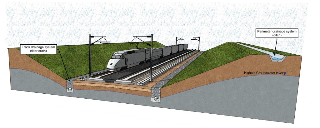
The main objective of the railway drainage system is to manage surface and groundwater to the level of service required to ensure the continual and safe operation of the HS2 trains. The railway drainage is provided in two dedicated and separated systems as follows (Figure 1):
- a track drainage system which intercepts the surface water runoff and sub- surface drainage from the track and generally any non-track areas within the HS2 curtilage (including below water-table groundwater); and
- a perimeter drainage system which collects surface water runoff and shallow groundwater from adjacent land and existing land drainage systems.
Slope drainage measures (e.g., counterfort drains) are used to intercept sub-surface infiltration, typically in cutting earthworks, and discharge it into the track drainage system. Groundwater may be considered in two ways:
- a dominant continuous water table, below which ground is permanently saturated; and
- a discontinuous, shallow perched water above the water table together with sub- surface infiltration through the unsaturated zone during times of rainfall infiltration.
Water tables (dominant groundwater levels in drainage design) will fluctuate with season, cyclically between wet and dry years, and potentially in the long-term with climate change.
The HS2 slab-track system will go through 41 separate cutting earthworks across Area North which represents a total track length of 35km. Track drainage systems in cuttings need to intercept surface runoff and sub-surface water generated from rainfall in the track construction (including the slab track, bituminous layer, hydraulic bound layer, track bed, the foundation and the cess) and the cutting slopes. In ‘wet’ cuttings with potential long-term water tables above (or within one metre) relative to track level, the design requirements are to keep groundwater in the long-term below the prepared subgrade and at a depth greater than 1.2m below the top of rail.
The BBV IPT assessed and shortlisted different drainage systems and configurations during Scheme Design. This multi-criteria assessment and sifting process considered capital cost, whole-life cost, programme, health and safety, environment, sustainability, constructability, maintainability and impact on communities. For the scenario of cuttings classified as ‘wet cutting’ in long-term or where the hydraulic condition was classed as unfavourable (i.e., long term water table or groundwater levels need to be capped below the prepared subgrade), one of the preferred track drainage solutions was the use of filter drains. Filter drains are aggregate-filled trenches with a perforated pipe at the base of the trench. The granular material used, which is typically exposed at the surface of the trench, allows for efficient removal of surface water runoff due to its higher permeability compared to the surrounding ground and also enables the removal of sub-surface water from the foundation whilst contributing to the control of groundwater levels (Stylianides, Frost, Fleming et al, 2015) [1]. The filter drains can therefore act as a combined surface water and groundwater drainage system, reducing land take and eliminating the need for dual drainage systems.
The attenuation features associated with track drainage systems using combined filter drains in cuttings need to consider the potential range of incoming flows from the groundwater ingress and the surface water runoff generated by the different storm events. Volumetric groundwater ingress, as defined by Darcy’s Law [4], is a product of ground permeability, hydraulic gradient and the area through which flow is occurring. With variability in all of these parameters, (both in terms of physical ground condition variability, in combination with temporal variation in groundwater levels), together with differing amounts of ground investigation data available across the route; there is potentially a risk of under or overestimation of groundwater baseflow. Such variation in potential baseflow, combined with consideration of third-party activities or climate change, could have a direct impact on the performance of attenuation systems during their design life.
This paper presents and describes the approach that was adopted by the BBV IPT on the basis of design for track drainage attenuation systems which intercept groundwater from cuttings. The structure of the paper is as follows:
- Description of the risk: this section describes the risk associated with the under or overestimation of groundwater ingress rates.
- Mitigation: how is the aforementioned risk mitigated, with a focus on the solution that was integrated into the basis of design.
- Implementation: how the approach was tested and successfully implemented in a number of assets during the Scheme Design Consolidation phase of the works.
- Conclusion: what are the learning legacy and further considerations for the construction and operation phases.
Description of the risk
General track drainage strategy
The track drainage system must dispose of the surface water and groundwater in a safe and controlled manner that is acceptable to the consenting bodies, such as the Environment Agency and Lead Local Flood Authorities. The disposal options shall follow the hierarchy:
- Infiltration into the ground by gravity.
- Discharge into the watercourse by gravity.
- Discharge into the surface sewer or highways drains by gravity.
- Discharge into the combined sewer by gravity.
- Discharge into a downstream system via pumping.
The potential for infiltration depends on the permeability of the ground, the dominant level of the groundwater table, the sensitivity of any underlying aquifer and the potential for any ground contamination. The scope for total infiltration in Area North is limited due to the ground conditions, particularly lower permeability ground conditions, in combination with relatively high water tables across a significant proportion of the route. The discharge from the various track drainage systems is therefore generally drained into a watercourse in the vicinity of the site areas. These discharges need to restrict runoff rates and volumes in line with Non-statutory Technical Standards for Sustainable Drainage Systems (Defra, 2015)[2] and, as a result, incoming flows need to be attenuated. Typical attenuation systems in Area North consist of balancing ponds and flow control chambers.
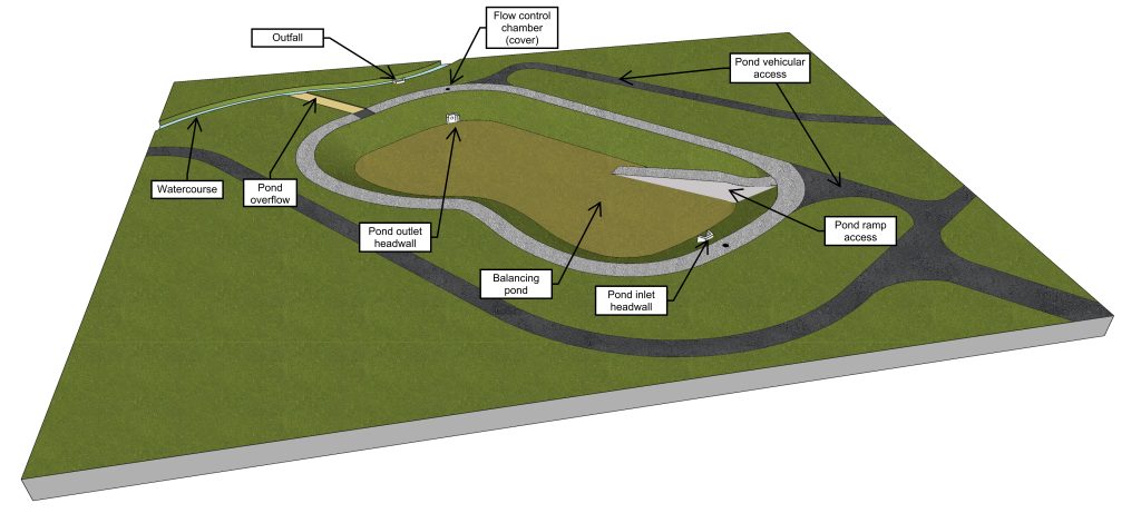
Balancing ponds in Area North are categorised as either infiltration basins, hybrid ponds or attenuation ponds. Infiltration basins rely on total infiltration of flows into the ground and are therefore unlined and they do not have a positive outlet. Although this type of pond is
preferred, the opportunity to use it in Area North is limited due to ground conditions. In areas where infiltration rates are poor, hybrid ponds can provide partial infiltration as they are unlined, but they are provided with an outlet for the discharge into any adjacent watercourse. Attenuation ponds also have an outlet, but unlike hybrid ponds, these are provided with an impermeable membrane to prevent groundwater pollution (e.g., tunnel seepage or fire flows). The membrane protects the long-term stability of earthworks or avoid groundwater ingress (i.e., groundwater draining into the pond) via the pond slopes or base. The typical arrangement of a balancing pond is in Figure 2.
A flow control reduces the rate at which water is discharged from a site and to the environment. This in turn reduces the flood risk to downstream watercourses and receptors. This discharge is restricted to the greenfield runoff rate of the predeveloped site. The adopted greenfield runoff rate is equal to QBAR (the mean annual flood) for all design storms up to and including a return period of 1-in-100 years with a climate change allowance of 40%. The storage in the balancing ponds fills with water during the design storm whilst the flow control maintains a reduced peak discharge rate to the watercourse.
The types of flow control chambers used in Area North consist of devices such as orifice plates, vortex flow controls, overflow pipes and weirs. Whilst orifice flow controls provide a linear relationship between head and flow rate, vortex flow control can provide a more constant discharge rate for different head levels, optimising storage volumes and reducing the risk of blockage. For this reason, vortex flow controls in combination with overflow pipes or weirs are the typical flow control systems used in Area North for track drainage systems.
The adoption of the combined groundwater and surface water drainage system requires the assessment of water quality and pollution risks associated with discharge of surface water into groundwater and vice versa. As HS2 will be electrified, designed to modern standards and without freight traffic, the risk of oil or other polluting substances making their way into the track drainage system and polluting surface water systems or groundwater is low.
Therefore, the general use of catchpits and sustainable drainage systems (SuDS) is deemed sufficient to mitigate the pollution risk to main rivers, ordinary watercourses and the ground, although specific risk assessments are undertaken in systems crossing Groundwater Source
Protection Zone 1 (SPZ1)[3]. In areas of contaminated ground or where polluted groundwater can be intercepted by the drainage system, a pollution risk assessment is undertaken for the final discharge into watercourses. In addition to these standard attenuation schemes, potential bespoke recharge schemes are being developed as part of Detailed Design to assist in the mitigation of portions of groundwater abstraction in aquifer catchments designated as either “over-abstracted” or “over-licensed” within the Environment Agency (EA)’s Catchment Abstraction Strategies[4].
Hydraulic design
The design of the track drainage system was undertaken as a fully integrated hydraulic model using a time step-based simulation package. In combined track drainage systems such as filter drains in cuttings, both surface water and groundwater flows need to be modelled.
Hydrographs for surface water flows are generated for a range of storm return periods and durations based on the runoff coefficients in the catchment, rainfall data from the Flood Estimation Handbook (FEH13, Stewart et al. 2013)[5] and other simulation parameters.
Groundwater ingress rates are subject to seasonal variations and potential long-term changes on groundwater levels as a result of factors such as climate change. However, the ingress rates are modelled as a constant baseflow in the hydraulic design for simplicity. The estimation of the groundwater ingress rates to track drainage is undertaken using both an analytical approach (Chapman, 1956)[6] and numerical modelling (for specific assets).
Conservative rates are estimated utilising geo-mean and upper-bound (90th percentile) permeability statistics for strata based on route-wide ground investigation. Design groundwater level assumptions for long term are taken as ‘characteristic’ groundwater level (considering maximum dominant groundwater level recorded in asset area), together with ‘ultimate’ groundwater level adding an additional 1m to maximum groundwater level recorded (or capped at ground level). Seasonal variations in groundwater level range from 0.5m to 2m, or between wet and dry years across the route. With this approach to the management of uncertainty associated with ground investigation data, and length of groundwater monitoring data records, this estimation provides a range of ingress rates which account for mean and maximum permeability values in both the short and long-term maximum groundwater level scenarios.
Flow controls and their associated restricted rates are modelled with head and flow curves which are generated based on the type of device used. These flow controls need to achieve a maximum discharge rate of QBAR for the design storm with return periods up to 1-in-100 years with a climate change allowance of 40%. As groundwater baseflows are constant they cannot be attenuated. As such the flow control needs to be increased to allow for the by- pass of baseflows.
Whilst the adoption of the worst-case ingress rate (i.e., maximum permeability and long-term scenario) is conservative for the estimation of capacity in track drainage systems such as pipes, and overestimation of ingress rates could lead to design risks in the attenuation and flow control systems as described in the following sections. The same applies to any underestimation of ingress rates.
Underestimation of groundwater ingress
If the design groundwater baseflows (QGdesign) have been underestimated, groundwater flows could deplete partially or totally the available storage within the balancing pond during a Dry Weather Flow (DWF) scenario. The available storage in the pond before a storm event would be lower than the value designed and, subsequently, this would provide a reduced
level of service and an increased flood risk to a watercourse or similar downstream of the pond.
Figure 3 illustrates how this difference between design groundwater baseflows (QGdesign) and actual groundwater baseflows (QGactual) can impact on the available pond storage during DWF. The figure assumes a vortex flow control which provides a maximum discharge restricted to QD, which is defined as,
(1)
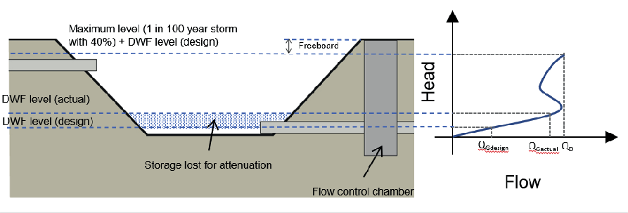
Although the pond is provided with a spillway overflow to prevent uncontrolled flooding and erosion during exceedance and failure events, the overflow will bypass flow controls and increase the discharge into the downstream watercourse. The risk of underestimating the groundwater ingress rates therefore requires mitigation.
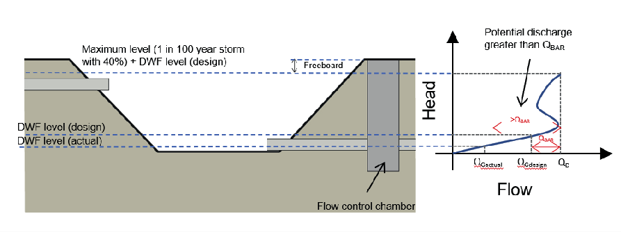
Overestimation of groundwater ingress
The estimation of groundwater ingress is used to size and specify the flow control as noted in Eqn. 1. An overestimation of groundwater ingress could result in flows greater than the greenfield runoff rate (QBAR) being discharged into the watercourse which could subsequently increase the risk of flooding downstream.
Figure 4 shows how the discharge under a design storm of 1-in-100 years with a climate change allowance of 40% can be greater than QBAR if the design groundwater baseflows (QGdesign) are greater than the actual groundwater baseflows (QGactual).
Generally, it is considered improbable that the quantity of the worst-case groundwater discharge would affect the main river flows (HS2, 2020)[7]. In addition to this, an assessment is undertaken in each discharge to confirm that the possible maximum discharge rate (during DWF and after storm events) does not increase the flood risk downstream. However, it is considered that mitigation for this overestimation risk is worth pursuing to provide further resilience and adaptability in the systems downstream for both frequent and more extreme storms.
Mitigation
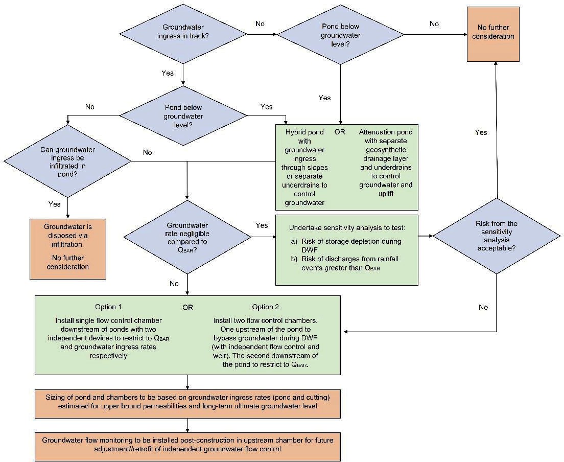
A design approach to mitigate against the risks of under and overestimation of groundwater flows was developed during Scheme Design Consolidation. The approach is described in this section and illustrated in the workflow in Figure 5.
The preferred method for managing the disposal of groundwater flows from cutting earthworks is via infiltration, where this is feasible from a water quality and quantity perspective. This can be achieved by both the use of infiltration basins and hybrid ponds, which are unlined. As noted in the previous sections, the ground conditions in Area North are such that the infiltration rates are low and therefore the potential of disposing flows via infiltration is minimal. In addition to this, the level of groundwater in the pond area should be assessed for both short and long-term scenario as it could limit the ability to infiltrate totally or partially.
A high groundwater table in the pond can be managed with different options:
- Hybrid ponds which let groundwater seepage in via the slopes.
- Hybrid ponds which are provided with a separate groundwater control system with underdrains.
- Attenuation ponds with geosynthetic drainage layer and underdrains to control groundwater level and uplift pressures.
Where groundwater flows cannot be completely disposed of via infiltration, mitigation may not be required if the maximum groundwater ingress rates are negligible compared to the QBAR rate. In this scenario, the pond and flow control are designed ignoring any groundwater flows (only for the design storm events). A sensitivity analysis is then undertaken in the design under DWF conditions (groundwater flows only) to estimate the maximum water level in the pond prior to a storm event. Finally, different tests are required to assess the performance of the pond and the discharges into the watercourse under the different return periods in combination with a range of groundwater baseflow estimates. If the impacts of risks associated with the under and overestimation of groundwater flows are negligible and acceptable, no further mitigation is required.
Where the residual risks associated with the above options are significant or unacceptable, further mitigation is required against the risk. This is generally required where the maximum groundwater baseflows are comparable or even greater than QBAR. The proposed mitigation is based on the following principles:
- Resilient permanent infrastructure: Pond and chamber structures are sized for a worst case scenario (maximum groundwater ingress rates). This provides resilience in the assets so they can adapt to potential changes in groundwater flows over time and the installation of worst-case flow control devices.
- Adaptable flow control: The flow control managing DWF are designed separately to the flow control limiting to QBAR. This allows the flow control managing DWF to be modified in isolation. Penstock valves are also installed in case of negligible groundwater ingress.
- Post-construction monitoring: The permanent infrastructure is sized to accommodate post-construction groundwater flow monitoring which is included in a design monitoring plan.
- Monitoring and adaptation: Following construction, it is required to adjust or retrofit the DWF flow control based on monitoring data for the asset design life to mitigate the residual risks with greater or lower ingress rates than estimated.
The flow control arrangement can follow two options:
- Option 1: Single flow control downstream of the pond with a minimum of two separate devices to restrict separately to QBAR and DWF groundwater baseflows.
- Option 2: By-pass inlet structure to divert the groundwater flow away from the main pond structure. The by-pass is provided with a flow control which will be limited to the groundwater flow rate. When flows exceed the groundwater flows under a storm event, water will overflow into the main pond structure. The main pond structure is provided with a flow control limiting the discharge to QBAR. This option is only feasible if the overflow level in the inlet structure does not promote backflow of the upstream system in any storm event.
The post-construction monitoring will be part of the Design Monitoring Plan (DMP) and would allow the IPT and HS2 to install a flow control device that will protect flood risk within and off the site. Groundwater flow depth and velocity will be measured in the pond during DWF for a minimum period of 12 months. This will generate data that could be assessed to select the most appropriate flow control device. The monitoring could continue further during the operation phase. Future changes in groundwater flows could be dealt with the retrofitting of flow control devices, providing resilience and adaptability.
All the options require a sensitivity analysis to be undertaken for the final balancing pond and flow control for a range of scenarios including storms up to 1-in-1000 years return period and maximum groundwater inflow. This should ensure that there is no flood risk impact to the HS2 track or other receptors.
Implementation
Basis of Design
The drainage design incorporates a total of 84 balancing ponds as part of the permanent works in Area North. Out of this, several ponds are associated to catchments of wet cuttings with combined surface water and groundwater systems. The mitigation approaches presented in this paper have been implemented in the completed basis of design. This basis of design has also been tested in the completed phase of Scheme Design Consolidation for all the ponds. The following sections describe how the approach was implemented in two ponds during the Scheme Design Consolidation stage.
Grand Union Canal Embankment
Grand Union Canal Embankment balancing pond is located near the Longhole Viaduct, adjacent to the Ridgeway Lane and approximately 300 meters to the north of the Grand Union Canal. The track drainage system upstream of the pond consists of trackside filter drains which collect surface water and groundwater from a section of Offchurch Cutting and Grand Union Canal Embankment and outfalls into an unnamed ordinary watercourse. The total gross area of the catchment is 9.9ha.
Grand Union Canal Embankment balancing pond, like Offchurch Cutting as a whole, is located on a combination of Helsby Sandstone and Mercia Mudstone. Due to the expected low infiltration rates and low risk of pollution, the pond is designed as a hybrid pond. From a design perspective, no infiltration has been assumed in the hydraulic model.
The pond is 2.6m deep and has a bed level of 64.50m Above Ordnance Datum (AOD). The long-term characteristic groundwater level in the pond is 63.90m AOD and the long-term ultimate groundwater level is 64.80m. The maximum groundwater ingress rate from the pond is 0.01 l/s. Due to the potential high groundwater table in the long term, underdrains are provided under the pond.
Groundwater is also assumed to be present in the section of Offchurch Cutting and is managed by the track drainage system. The maximum groundwater ingress rate for the section of cutting is 34.0 l/s. This ingress is assumed to be evenly distributed along the track drainage system and has therefore been hydraulically modelled as an evenly distributed baseflow. The greenfield runoff rate (QBAR) and the range of groundwater ingress rates for different permeabilities and estimated levels is in Figure 6.
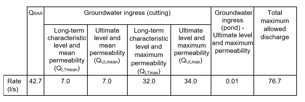
If a single flow control is set to QBAR value of 42.7 l/s downstream of the pond, testing during the DWF scenario indicated that an assumed groundwater ingress of 34 l/s (QULmax) into the pond resulted in a depleted storage volume of 387 m3. This would reduce the available storage before a storm event and meant additional storage would be required to deal with the 1-in-100 years with a climate change allowance of 40%. On the other hand, if additional storage is provided above the DWF and the flow control is set to restrict flow to QBAR and QULmax, which is a total value of 76.7 l/s, there is a risk that equivalent discharges from storm events could be higher than QBAR if the actual ingress rate is lower than assumed.
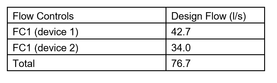
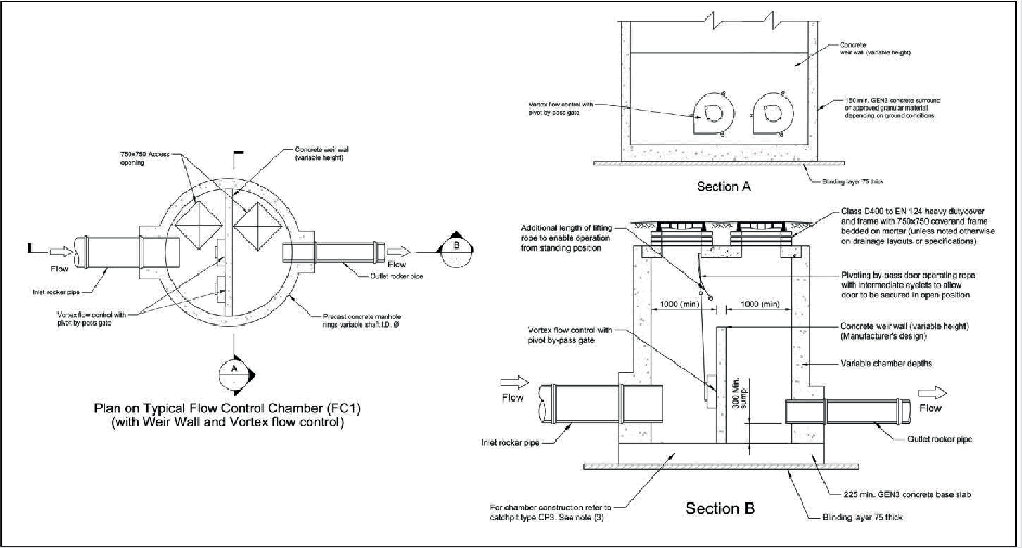
The solution implemented in this pond to address this challenge involves the provision of a single flow control chamber downstream of the pond (FC1) as shown in Figure 8. The chamber is provided with two vortex flow control devices parallel to each other at the same level (Figure 9). Each flow control is set to a maximum discharge rate equivalent to QBAR and QULmax as shown in Figure 7. The pond and the flow control chamber are sized for the maximum estimate of groundwater ingress rate (34.0 l/s) to provide a future proofed solution. The design includes a flow monitoring chamber which will allow the actual rate of groundwater ingress following construction to be recorded. This data will be used to adjust or retrofit one of the flow controls to limit discharges into the watercourse in line with the observed groundwater ingress rate. The monitoring can continue during the operation phase and this will allow the operations and maintenance team to adjust one of the flow controls should rates change in the future. An overflow spillway channel has been included in the pond at the maximum attenuation level, 300mm below the maintenance access bench or top of the pond.
The hydraulic simulation results based on groundwater baseflows equivalent to QULmax (34 l/s) indicate:
- In the DWF scenario, the water level in the pond could go up to 160mm using a volume of 387m3 whilst the discharge is limited to 34.0 l/s.
- In a 1-in-100 years with a climate change allowance of 40%, the water level is below the pond’s freeboard and spillway overflow level using a total volume of 6,631m3 and the discharge is limited to 76.7 l/s.

Swinfen Cutting
Swinfen Cutting balancing pond is located north of Black Brook and east of the HS2 main line (SnakeGrid 180743.7876 , 412209.119). The track drainage system upstream of the pond consists of trackside filter drains which collect surface water and groundwater from Swinfen Cutting and outfalls into Black Brook which is designated as a main river The total gross area of the catchment is 16.88ha.
Swinfen Cutting balancing pond, like Swinfen Cutting as a whole, is underlain by bedrock geology comprising the weathered profile of the Sherwood Sandstone Group. Bromsgrove Formation, Kidderminster Formation and the Hopwas Breccia Formation were all encountered at or near existing ground level. Due to the low infiltration rates and the negligible risk of pollution, the pond is designed as a hybrid pond. No infiltration has been assumed in the hydraulic model.
The pond is 3.1m deep and has a bed level of 78.38m AOD. Both the long-term characteristic and ultimate groundwater level in the pond is estimated as the ground level at
81.48m AOD. As such, the pond volume will be slightly depleted by a maximum groundwater ingress rate of 4.0 l/s, estimated based on ultimate level and maximum permeability.
Groundwater is also assumed to be present in Swinfen Cutting and is managed by the track drainage system. The worst-case groundwater ingress rate for the section of cutting is 100.6 l/s and this has been distributed as a base flow along the track drainage system in the hydraulic model. The greenfield runoff rate (QBAR) and the range of groundwater ingress rates for different permeabilities and estimated levels is in Figure 10.
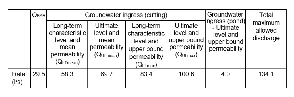
If a single flow control is set to the total maximum allowed discharge value of 29.5 l/s (QBAR) downstream of the pond, testing during the DWF scenario indicated that an assumed groundwater ingress of 100.6 l/s and 4.0 l/s (QULmax) resulted in the pond being completely depleted before any storm event. On the other hand, if additional storage is provided above the DWF and the flow control is set to restrict flow to QBAR and QULmax (134.1 l/s), there is a risk that equivalent discharges from storm events could be higher than QBAR if the actual ingress rate is lower than assumed.
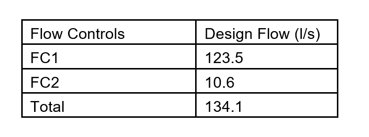
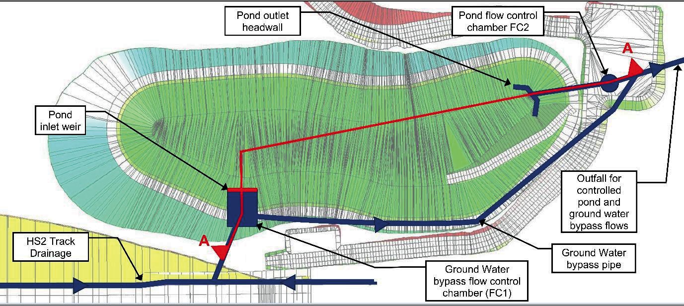
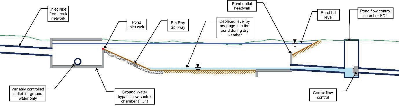
As such a groundwater bypass option was implemented to separate the cutting groundwater baseflows from the pond and prevent any increase in flood risk within the site or downstream. As shown in the arrangement in Figure 12 and 13, a bypass flow control chamber (FC1) is proposed to divert the baseflows upstream and around the pond without attenuation during DWF. This bypass chamber will be provided with a weir to allow surface water from a storm event to enter the pond. This chamber will be provided with a vortex flow control. A second and independent flow control chamber FC2 is provided downstream of the pond. The following design rates and restrictions in each flow control were adopted and resulted in a DWF depth of water in the pond of approximately 342mm.
Assuming a groundwater ingress rate equivalent to QULmax from the cutting and the pond (100.6l/s and 4.0l/s), the hydraulic simulation results indicate:
- In DWF scenario, the water level in the pond could go up to 342mm using a volume of 690m3 and the discharge is limited to 104.6 l/s.
- In a 1-in-100 years with a climate change allowance of 40%, water level is below the pond’s freeboard and spillway overflow level using a total volume of 10,470m3 and the discharge is limited to 134.1 l/s.
Conclusion
As demonstrated through the sections of the paper, the uncertainty on the estimation of groundwater ingress can have direct impact on the track drainage attenuation system and ultimately in the flood risk downstream of HS2. The proposed mitigation in this paper could prove useful for drainage infrastructure works where it is acceptable from a water quality perspective to intercept groundwater and surface water in a combined system. The approach presented can also offer adaptability and resilience to any new drainage infrastructure.
The approach has been implemented in a completed phase of the design works (Scheme Design Consolidation). Due to the uncertainty in ground conditions and therefore estimates on groundwater ingress, new ground investigation data may require revision of rates prior to construction. The flow monitoring that will be installed post-construction is a key aspect of the proposal and will need to be followed by the adjustment or retrofit of flow controls that adapt to the observed values. This could be applied during the design life of the asset for the operational phase of the works.
Acknowledgments
The authors would like to acknowledge the wider IPT who contributed to the design and delivery of permanent drainage works, particularly Kristy Cheang and Nathan Rudge who were part of the BBV Design Joint Venture (DJV) involved in the design of the balancing ponds described in the paper.
References
- Stylianides, T, Frost, M. W., Fleming, P. R., l-Jaber, A., Mageean, M, Huetson and Klimczak, T. (2015). Highway Filter drains: precursors for maintenance management. Infrastructure Asset Management Volume 2 Issue 4 – Institution of Civil Engineers Publishing.
- Defra (Department for Environment, Food and Rural Affairs) (2015) Non- statutory Technical Standards for Sustainable Drainage. Defra, London, UK.
- Environment Agency (2019) Manual for the production of Groundwater Source Protection Zones. Environment Agency, Bristol, UK.
- Environment Agency (2021) Abstraction licensing strategies (CAMS process). Environment Agency, Bristol, UK.
- Stewart, E. J., Jones, D. A., Svensson, C., Morris, D. G., Dempsey, P.,Dent, J. E., Collier, C. G. & Anderson, C. A. (2013) Reservoir Safety –Long Return Period Rainfall. Project FD2613 WS194/ 2/39 Final Report (two volumes). London, UK..
- Chapman (1956); in Mansur and Kaufman (1962), CIRIA 570 Groundwater Control: design and practice, 2nd ed. (2016) – Construction Industry Research and Information Association, London, UK
- High Speed Two (2020) Guidance Note – Groundwater Drainage and Treatment HS2-HS2-EV-NOT-000-000035 (revision P01). High Speed Two, UK.
Peer review
- Ruby Kitching Institution of Civil Engineers (ICE)