Benefits of steel-concrete bridges with double composite action
The paper aims to discuss the advantages and disadvantages of the double composite section in high-speed railway bridges from the design, construction and maintenance point of view. The paper is centred around the differences between single and double composite sections.
Steel composite construction has been extensively adopted in the last 60 years for small to long span bridges (up to 200m). In composite bridge decks, the steel structure works together with a concrete slab to resist flexural stresses and to control deflections. These decks work efficiently in mid-span regions where the top concrete slab deals with the compression forces whilst the steel structure resists the tensile forces from the positive bending moments.
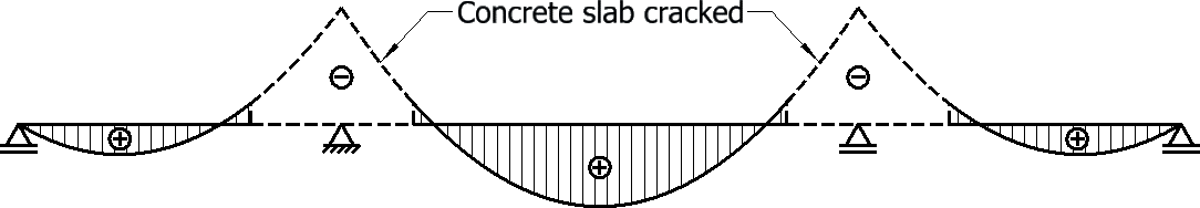
The efficiency is lost over the intermediate supports where hogging bending moments develop. In these regions, the concrete slab tends to crack leading to an increase in reinforcement to control the tension forces. Similarly, the steel structure below requires additional stiffeners to prevent local or global instability under the compression forces.
To improve the structure’s effectiveness, the double composite section is proposed for the intermediate supports regions. The section adds a concrete slab to the lower (compression) flange of the superstructure. This results in savings in structural steel, reduction in cross frame requirements and in gains from the additional bracing at midspan due to the bottom slab. The advantages go further, and additional benefits can be seen for high-speed rail bridges: improved dynamic response (increased damping, heavier deck, enhanced torsional stiffness) and limited deck end movements due to the increased stiffness; all leading to an increased passenger comfort and a more economical design.
The disadvantage is that all of these benefits come with an added stage during construction, casting the bottom slab, and increase loads transferred to the substructures.
- Written by
-
Razvan Capra (Arcadis/EKFB)

-
Pere Alfaras Calvo (Arcadis/EKFB)

- Resource type
- Resource type: Technical Paper
- Intended audience
- Consultants
- Tags
- BridgeDesign, CompositeConstruction posts
Notation
MEd – Design bending moment
MRd – Design value of the resistance to bending moments
Background
Steel-concrete composite bridges have existed for more than a century and have been designed to cover a very wide range of spans. One of the first steel-concrete composite beam bridges in Europe was the Acheregg Bridge, Switzerland. Built in 1914, the bridge had a modern look reinforced concrete slab and beam cross section and accounted for the load to be carried through a friction bond[1]. A more modern example is the Queensferry Crossing built in Scotland in 2017. The three-tower cable-stayed bridge has an approximative 40m wide and 2.7km long steel-concrete composite deck.
Steel and steel-concrete composite form or construction have always competed with concrete structures when trying to find the best alternative for cost, durability and now, more recently, carbon footprint. The most common steel-concrete composite bridges, the short to medium span range (20 to 50m) come in the form of beam and slab configuration. For longer spans, up to 500-600m, arches and cable stayed bridges are preferred.
The common representation of steel-concrete composite decks shows a top concrete slab working together with the steel structure, reducing deflections and increasing the strength of the structure (increased area, moment of inertia etc.). The connection is done using shear connectors fixed to the steel flanges and embedded into the concrete slab that make the two materials to work compositely. These decks work efficiently in mid-span regions where the top concrete slab deals with the compression forces whilst the steel structure resists the tensile forces from the sagging bending moments. The double composite steel-concrete bridges on the other hand also use a bottom concrete slab over the intermediate supports, in the hogging bending moments region.
There aren’t many records of double composite bridges prior to early 2000s, although the concept is not new. According to Stroh[2] several bridges were built in Spain, Germany and Hong Kong towards the end of the 20th century. The Ciervana Bridge in Spain, built in 1978 was the first double composite bridge built anywhere in the world. A few other structures were built in Germany in the early 1990.
Although not previously attempted in the UK, double composite bridges have been researched and projects carried out in mainland Europe. An increased interest developed in recent years for double composite bridges, mainly due to the new high-speed railway projects that sought alternatives to overcome some of the buildability, programme and cost disadvantages of the heavier prestressed concrete decks.
The paper aims to discuss the advantages and disadvantages of the twin I girder double composite section in high-speed railway bridges from the design, construction and maintenance point of view. The paper is centred around Small Dean Viaduct, one of the most prominent structures on the central section of High Speed Two (HS2) Phase One works and around the differences between single and double composite sections.
Concept design
The steel-concrete composite decks work efficiently when the concrete slab is in compression and the steel beams deal with the tension stresses (mid-span regions).
The efficiency is lost and some design difficulties appear for the regions over the intermediate supports, where hogging bending moments develop. In these regions the top concrete slab tends to crack leading to an increase in reinforcement to control the tension forces (Figure 1).
Similarly, due to high compression stresses, the steel structure below requires additional stiffeners and/or bracing systems to prevent local or global instability under the compression forces.
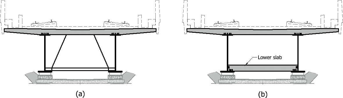
To improve the structure’s effectiveness, a lower concrete slab, sitting on the girders’ bottom steel flanges, connected with these and part of the web, is proposed in the hogging bending moment regions (Figure 2). This bottom slab is added in the compression zone of the composite girder, making the best use of the material and placing it where it’s most efficient. It also “closes” the section, transforming the open, twin I-girders composite deck into a box section. The very stiff, lower concrete slab also provides stability to the steel girders’ bottom flanges, reducing the need for additional plate stiffeners or bracing systems.
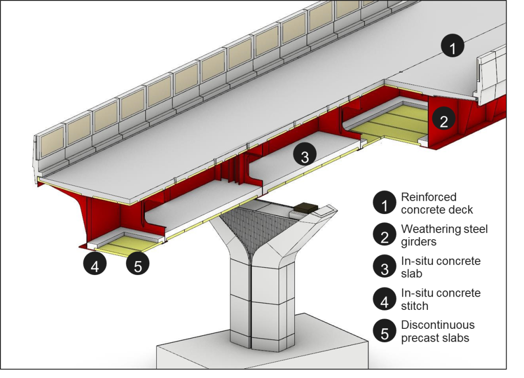
For Small Dean Viaduct, the bottom slab has been extended along the entire deck bringing it in line with the “strict box” type of decks, as firstly described by Julio Martinez Calzon[3]. An in-situ reinforced concrete slab has been added over the pier regions. Outside this area, in the midspan regions, discontinuous precast concrete planks and an in-situ stitch pour running along the main girders’ and diaphragms’ bottom flanges were provided (Figure 3).
As the slab outside the support regions is not continuous, it does not participate in the global flexural resistance of the deck. The main role of the precast planks and in-situ stitch is to enhance the superstructure’s torsional resistance as described in the next sections of this paper.
From a structural point of view, when compared with the conventional steel-concrete deck, the “strict box” arrangement used for Small Dean Viaduct superstructure, the double composite steel-concrete action along the support regions and the discontinuous precast planks with the in-situ stitch achieves the following main benefits:
- Increased flexural resistance to hogging bending moments
- Enhanced stability for the bottom flange
- Reduced deck deformation and improved dynamic response
- Improved torsional resistance
- Simpler steel fabrication details and increased fatigue resistance.
This results in savings in structural steel, reduction in cross-frame requirements and gains from the additional bracing at midspan due to the bottom precast panels and in-situ concrete stitch. The advantages go further, and additional benefits can be seen for high-speed rail bridges: improved dynamic response (increased damping, heavier deck, enhanced torsional stiffness) and deck end movements due to the increased stiffness; all leading to an increased passenger comfort and a more economical design.
Furthermore, the build-up of steel girders and concrete slab result in a closed box section that brings additional benefits such as:
- Creates a suitable enclosure for services or for the bridge’s drainage system. At Small Dean Viaduct the entire drainage system is hidden inside the box to enhance the structure’s appearance. This also simplifies the maintenance and inspection of the drainage system.
- The double composite box structure creates less noise as it limits the re-radiant noise coming from wheel-track induced vibrations.
Double composite decks analysis – Case study: Small Dean Viaduct
The strength and behaviour of two options for the Small Dean Viaduct’s superstructure are analysed and compared. The first option is the chosen solution for the HS2 viaduct, a double composite steel-concrete deck with cantilever fins either side of the main girders (Figure 4). Option 2 derives from Option 1 (steel bracings replacing the bottom concrete slabs) and is a conventional steel-concrete composite superstructure as shown on Figure 5. The two options were assessed based on the current design standards used for the detailed design of the viaduct (Eurocodes including UK National Annexes and additional complementary HS2 standards).
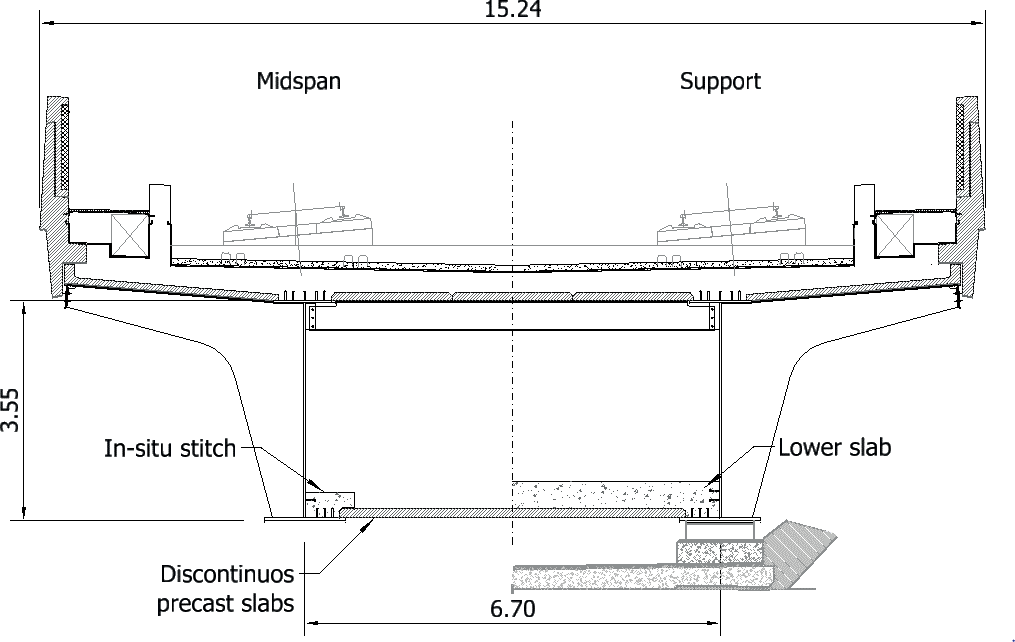
The proposed structure will be a 346.40m long continuous viaduct. The span arrangement consists of 7 spans of 41.45m – 51.50m – 55.50m – 49.50m – 55.50m – 51.50m – 41.45m. The deck depth of 4.933m from the lowest rail to the deck soffit is constant along the full length of the viaduct. The overall width of the deck is 15.24m, including lateral concrete parapets.
For both options, the top reinforced concrete slab is supported on two steel I girders spaced at 6.7m transversely. The concrete slab is 14.33m wide, and its thickness varies from 0.3m at the edges to 0.51m above the main girders and to 0.44m at the centre of viaduct. Precast concrete planks form the formwork for the top slab. The planks are supported on the main girder’s top flanges, a series of cantilever fins’ top flanges and steel transoms.
For Option 1, a series of precast concrete slabs are supported on the bottom flanges of the main girders and diaphragms. Six concrete lower slabs 22.1m long and 400mm thick rest on top of the formwork planks over each pier (Figure 4). At midspan regions, the formwork planks are connected to the steelwork with an in-situ stitch. For Option 2, the bottom concrete elements have been replaced with a steel bracing system at the level of the bottom flanges.
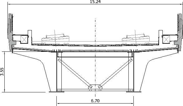
For both options, the overall structural depth of approximately 4.13m is constant for the full length of the viaduct, including the depth of the steel girders of 3.55m between the two extremes faces of the flanges. In addition, steel fins are added on each side of the steel beams with variable spacing between 1.00m and 3.10m.
A robust kerb connected to the deck slab provides the derailment containment system for the railway. Precast concrete parapets are included at the deck edges and act as noise barriers, with a minimum height of 1.85m above low rail level.
Bending, shear and deformations
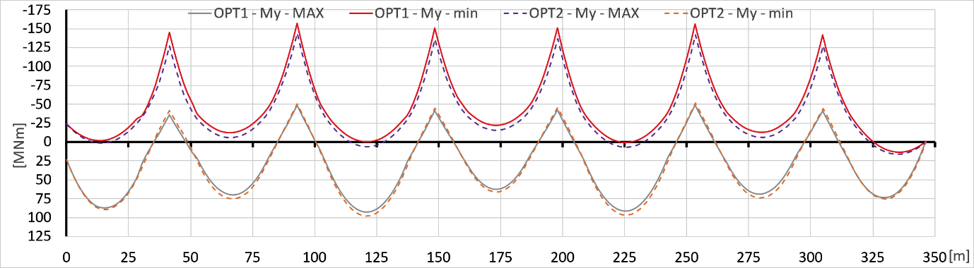
The global flexural analysis showed little difference in means of design applied bending moments and shear forces. An expected shift in overall values from hogging regions towards the middle of the spans can be seen in Figure 6. This is mainly due to the decrease in stiffness over the supports when the bottom concrete slab is omitted (Option 2).
The absence of the bottom concrete slab over the pier regions has a more significant impact when assessing the resistance to bending moments. For Option 2, the pier sections are class 3 sections whilst the double composite arrangement keeps these highly stressed sections in the plastic bending moment resistance domain (class 2 sections). There is very little difference for the resistance to shear forces as the stresses are carried mostly by the webs, which are kept identical for both options.
Figure 7 below summarizes the main differences between the two options.
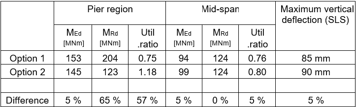
As seen above, if the same steel plate sizes are to be used for both options then for Option 2 the structure would fail the bending moment design criterion in the pier regions (MRd < MEd).
To bring the utilisation of the section’s capacity below 100%, it is necessary to increase the plates’ sizes along the pier regions. This alone (excluding the 5-10% increase needed for bracings and additional stiffeners) would result in a 6-7% increase in steel weight only for the pier sections (increasing the width of the bottom flange rather than modifying the depth of the section). If we consider the fact that the viaduct will be launched, the increase in steel weight would be approx. 12%, as the bottom steel flanges would require a constant width along the entire length of the viaduct. The alternative to increasing the width of the bottom flanges would be to have a balanced increase of both thickness and width for both top and bottom flanges. But increasing the thickness beyond a certain value would cause significant problems related to brittle fracture. This might, in turn, cause greater problems during fabrication and/or with the procurement of the higher subgrade steels needed because of these thicker, highly stressed steel plates.
The addition of the concrete bottom slab for the double composite option reduces the vertical deck deflections by approximatively 5% for the longer spans and by 2% for the end spans. The increased stiffness brought by the double composite section improves the dynamic response of the structure as well.
For the double composite box section, the torsional response of the deck is much improved when compared with the conventional steel-composite option.
The analysis showed the latter to have higher vertical displacements and rotations in an asymmetric load scenario when only one side of the bridge is loaded (trains on one track only).
The mechanism behind the torsion resistance of the double composite deck is presented in the next section of the paper.
Torsional resistance
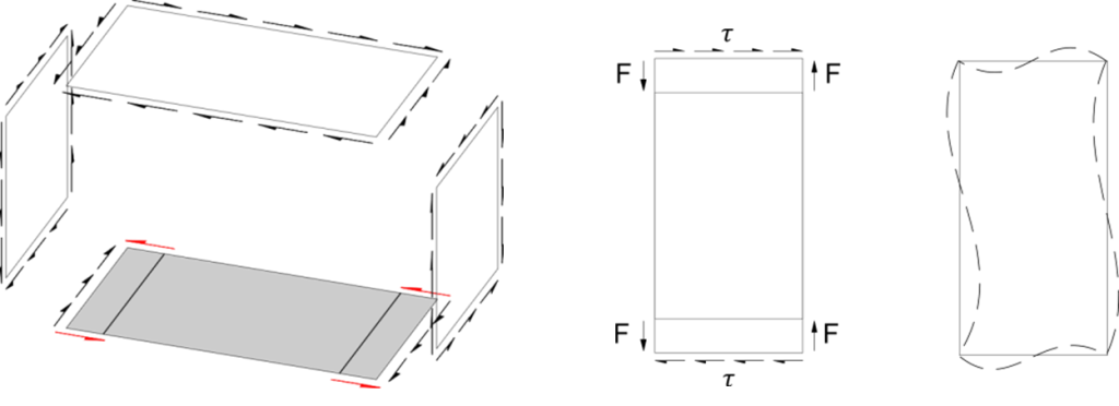
The torsional response of box girders is typically estimated by the thin-walled closed cross section equations known as Bredt’s formulas. This is applicable to prismatic beam sections and allows derivation of shear stresses in the box walls given a torsional moment.
By following this approach, each wall of the closed box section is subjected to pure shear and leads to pure shear deformation (see Figure 8).
In Small Dean Viaduct the torsional shear stresses and deformation can be assessed by this approach for the sections close to the piers where a closed box is achieved by the two main girders and the top and bottom in-situ concrete slabs.

However, at midspan regions there is no bottom in-situ concrete slab, but instead precast concrete planks connected through a concrete stitch. This invalidates the principle of a prismatic beam, due to the discontinuity existent between the precast planks. This means that the discontinuous precast planks are not under pure shear, but a different stress state. A shear flow is expected at the connection between the bottom planks and the main girder webs. This shear flow is transferred through the in-situ concrete stitches. Due to deformation compatibility, these in-situ stitches will be subjected to in-plane bending together with the precast planks.
The precast slabs and in-situ stitch need to be designed for both in-plane forces and out-of- plane bending. For the former, Millanes et. al. [3] propose a strut-and-tie approach. In this paper a similar approach is presented.
The precast plank behaves against in-plane forces in a similar fashion as a shear wall. A simple strut-and-tie model can be constructed as shown below in Figure 10. Despite the model depicting localized struts and ties, the required reinforcement will be distributed along
the length of the precast plank. Transversal reinforcement is also required to transfer the resulting in-plane bending.
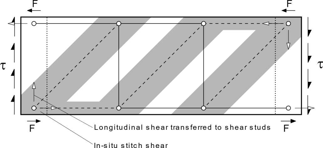
The in-situ stitch plays a fundamental role on closing off the torsional shear stress flows. On one hand, the stitch transfers the shear longitudinal flow (shown as in Figure 9) to the main girders through the shear studs on both the main girder bottom flange and web. On the other hand, provides longitudinal continuity transferring the transversal shear forces (shown as F in Figure 10) between consecutive slabs. This requires the in-situ stitch to be designed under horizontal bending and shear.
Construction details
The two options do not differ greatly when it comes to construction method or details. There are some particularities of the double composite decks that might have a slight impact on the programme and duration of works and could also add some complexity to the details. These are linked to having to cast the additional bottom slabs, both over the pier and along the mid- span regions (precast panel stitch).
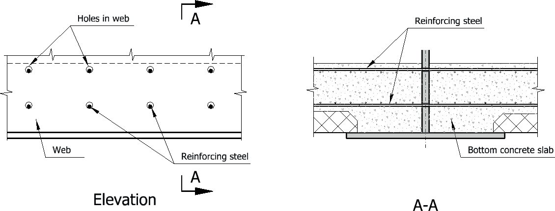
For the mid-span sections of Option 1 the precast concrete planks could easily be dropped down into position, supported on the bottom flanges, and have the stich cast with limited formwork needed. The weight of the wet concrete for the slab sections over the intermediate supports would require a form of temporary support (precast concrete planks, formwork etc.). The composite action between the bottom slabs (support and mid-span regions) can be achieved with conventional shear connector distributed along the bottom flange and lower part of the webs. Alternatively, the shear connection could be achieved by installing reinforcement in pre-drilled holes in the diaphragm and/or main girders’ webs (similar to “perfobond” concept, Figure 11).
Other construction details that need to be considered include:
- Small openings/holes are required in the bottom slabs to allow for proper ventilation and drainage of the box girder
- Access provisions need to be in place for future maintenance and inspections of the box girder
- The deck drainage system needs to be tailored to facilitate the easy replacement of pipe sections and any other element if running it inside the box.
Conclusions
This paper has shown that a reduction of about 10-15% in steel weight can be achieved when a bottom concrete slab is introduced for the intermediate support cross-sections of conventional steel-concrete composite superstructures. This saving in structural steel weight comes together with simplified fabrication details by designing out the bottom flange level bracing system and, in some cases, the bottom flange stiffeners (box girders). Alternatively, the total structural depth of the deck could be reduced allowing lower elevation over cleared assets, leading to reduced height approach embankments, and lower profile architectural enhancements.
The advantages go further, and additional benefits can be seen for high-speed rail bridges, especially when extending the bottom slab along the entire structure: improved dynamic response (increased damping, heavier deck, enhanced torsional stiffness) and deck end movements due to the increased stiffness; all leading to an economical design.
The main disadvantage comes in the form of added complexity during construction together with a longer duration of the works. This is mainly due to the additional stage needed to install the precast planks and cast the bottom in-situ concrete slab and stitches along the deck. The double composite superstructures are heavier than their conventional counterpart as the bottom concrete elements increase the loads transferred to the substructures and might require bigger bearings and could slightly increase the cost of the substructures.
Acknowledgments
The authors acknowledge High Speed Two, EKFB, Moxon Architects, Eiffage Metal and Buckinghamshire Council for their contributions in realising the design of Small Dean Viaduct.
References
- Pelke, E and Kurrer, K-E. (2015) On The Evolution Of Steel-Concrete Composite Construction. Fifth International Construction History Congress, Chicago, 06/2015
- Stroh, S.L. and Sen R. (2000) Steel Bridges with Double-Composite Action: Innovative Design. In: Transportation Research Record Journal of the Transportation Research Board, 2000
- Millanes, F. (2008) Outstanding composite steel-concrete bridges in the Spanish HSRL. In: Proceedings of the 7th International conference on steel bridges. Guimarães, 2008
Peer review
- Tomas GarciaHS2 Ltd
- Ruby KitchingInstitution of Civil Engineers (ICE)