Birmingham Curzon Street Station: A 21st Century Station Roof
Birmingham Curzon Street Station is the planned new northern terminus for Phase One of High Speed Two (HS2), located in the city centre of Birmingham. The Curzon Street Station roof is defined by its efficiency, simplicity and elegance, measuring 280m long by 80m wide and with a clear span of 70m metres over the station’s western concourse where it rises to a height of 15m.
The objective of this paper is to summarise the design process undertaken between the engineers and architects to develop the design of the light-weight self-supported station roof.
The paper discusses the process undertaken to derive the structural form of the roof, as a response to the site, functions of the station and its expression as a 21st century train shed. It then summarises the structural design process of the highly efficient parabolic structure, developed through extensive research and analysis. It is envisaged that this new knowledge and capability would be useful on future large-scale building projects where lightweight design and visual elegance are important aspects of the design specification.
Successful collaboration between architecture and engineering was fundamental to the design of the roof. The paper discusses key elements of integration with the architectural design, including the buttress columns which are expressed externally to form an integral part of the architectural story of the station’s facade.
The paper concludes with a summary of three options considered for the construction methodology and sequencing of the roof, with safety thinking and a modular approach at the forefront of the design.


Introduction
Birmingham Curzon Street Station (BCS) is the planned new northern terminus for Phase One of High Speed Two (HS2), located in the city centre of Birmingham. It will be the UK’s new central hub for the high-speed (HS) rail network, connecting Birmingham to London Euston, before the subsequent phases extend further northwards to link Manchester and Leeds. Once completed and fully operational, BCS will have seven terminal platforms serving 65,000 passengers per year.
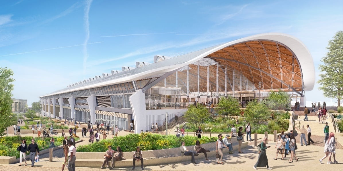
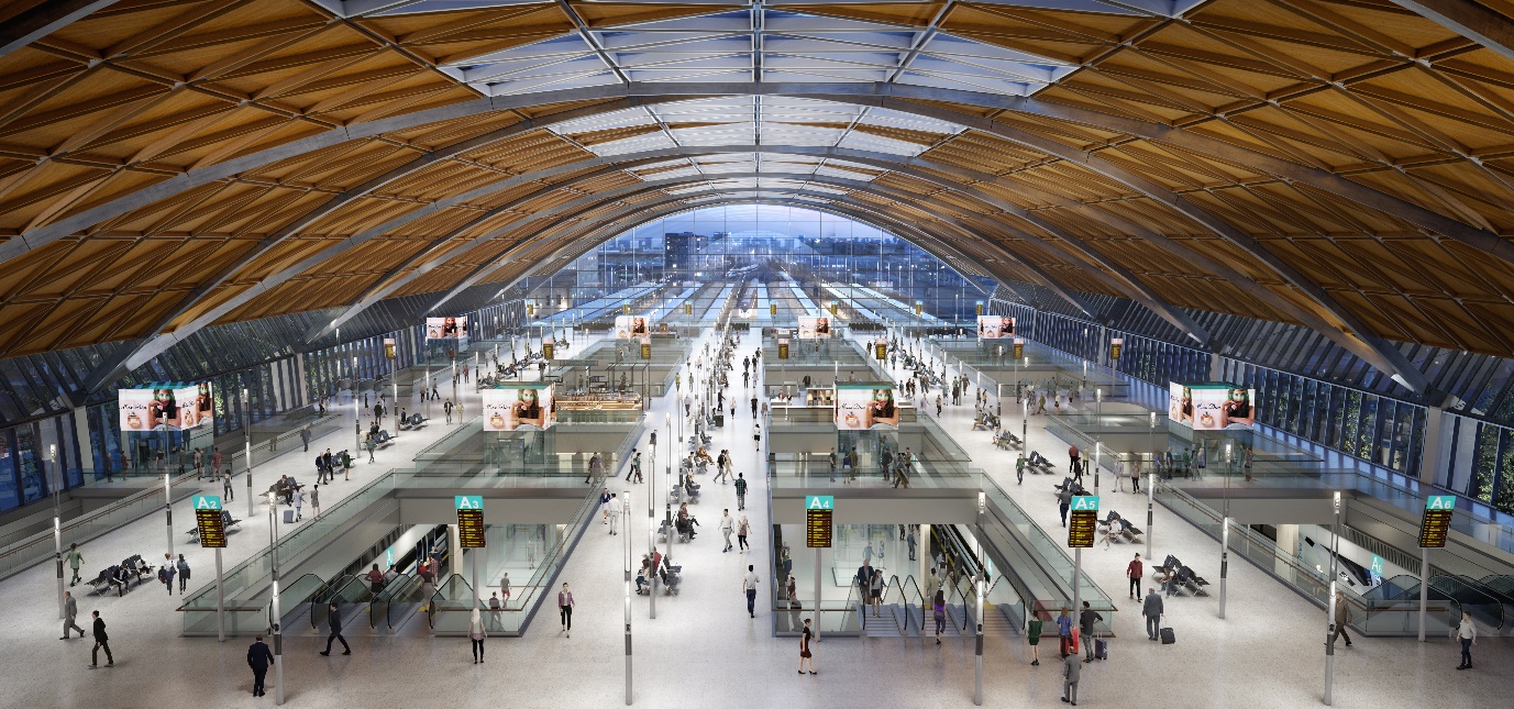
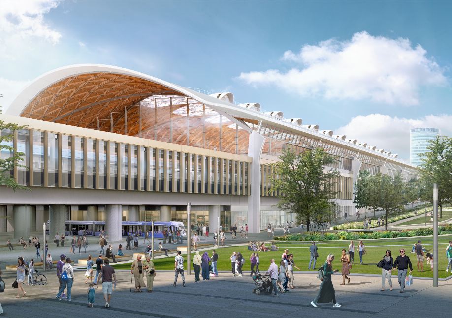
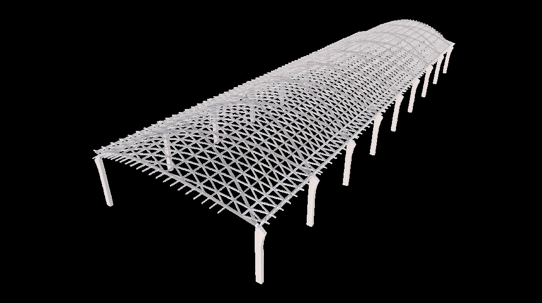
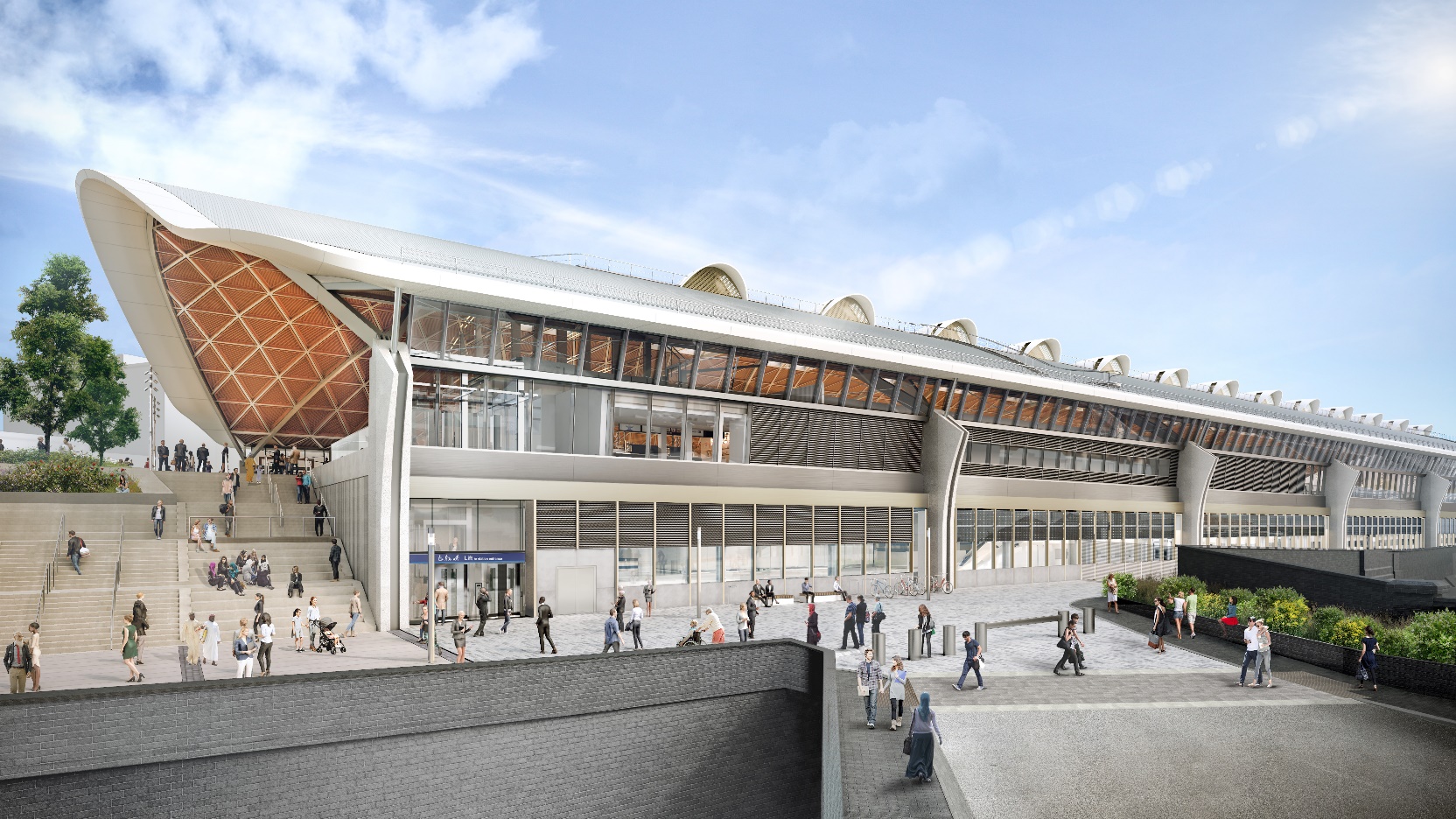
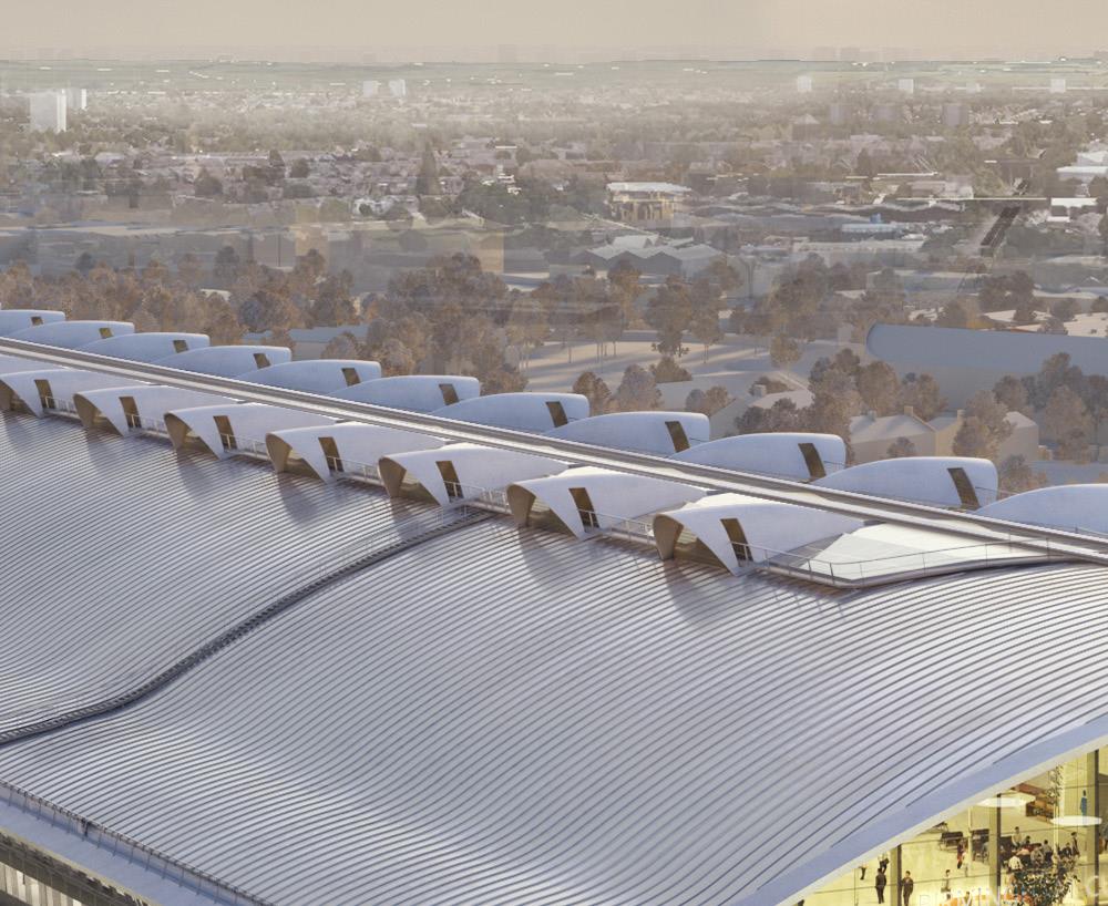
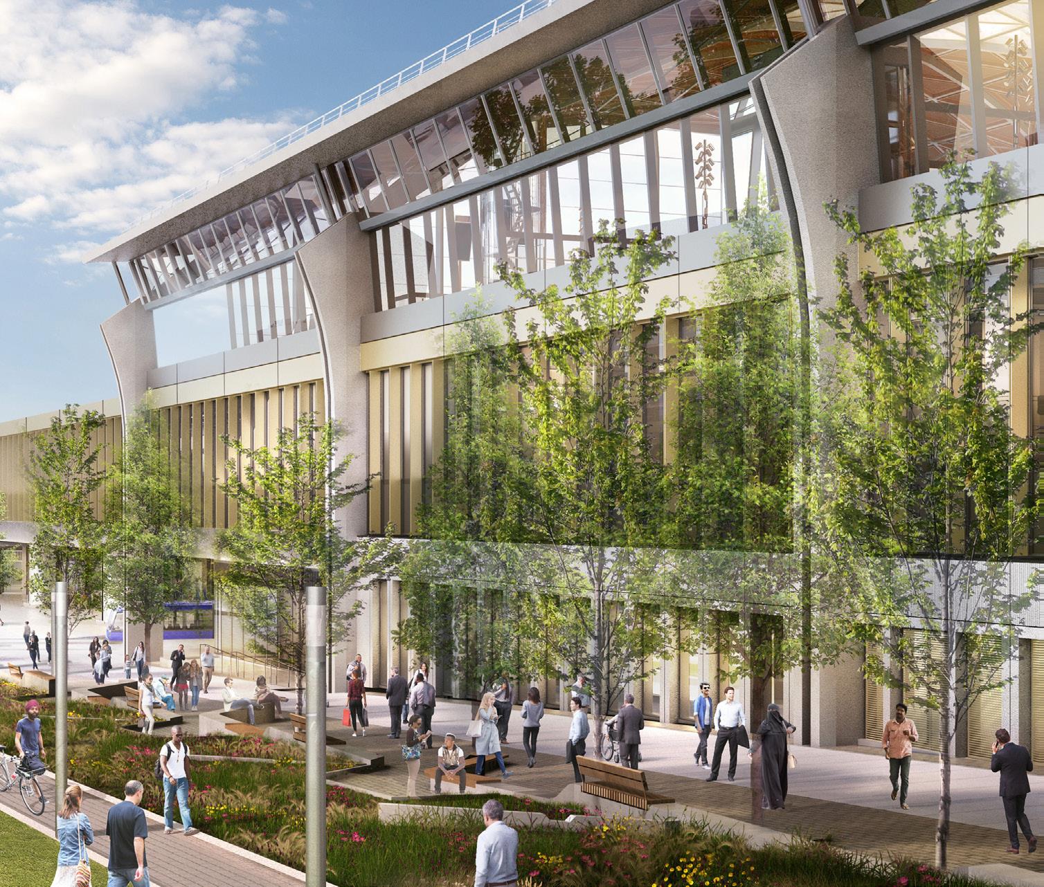
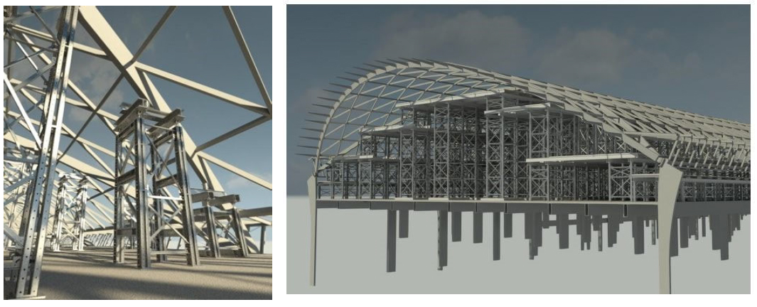
Due to the planned length of the HS trains, the platforms are over 400m long, requiring the main station building to be 280m in length to provide covered access via the paid concourse to the platforms. The design vision is for the terminus building, shown in Figures 1 to 3, to be fully open-plan to create a sense of spaciousness and grandeur, and so the design required the 70m-wide arched roof to be fully self-supporting without any internal columns, while still retaining a lightweight, elegant feel to its construction.
This technical paper summarises the structural form, the design and analysis undertaken including coordination with the architectural design and the construction methodology and sequencing considered as part of the design of the station roof.
Structural Form
Response to Site and History
The proposed building’s form is derived from a response to the site; the functions of the station and its expression as a 21st century train shed. The design seeks a simple, legible articulation of the constituent parts of the building, whilst seeking to create an inspiring piece of modern architecture.
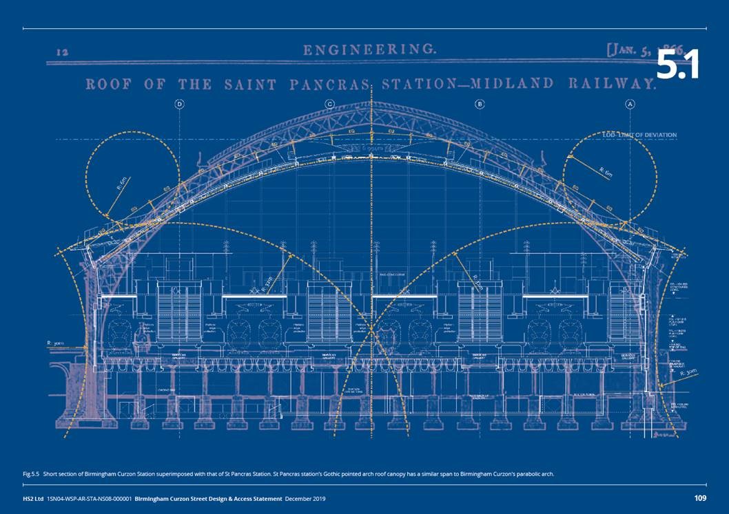
The span of the station roof is similar to the roof of St Pancras Station’s Gothic pointed arch roof canopy, as illustrated in Figure 4. The BCS roof design seeks to achieve a modern interpretation of the traditional 19th century iron and glass train sheds with overarching roof canopy, using innovative design methods to produce a highly efficient structural form.
The station intends to mark its identity on the city’s skyline with a simple, elegant and refined arch, creating a clear destination point for both passengers and the local community alike.
Attention to detail and well-crafted elements underpin the design, anchoring it within the industrial heritage of the West Midlands. The quality of design, material and construction of the building’s roof arch is considered imperative in placing the new terminus building as a significant landmark in the city of Birmingham for future generations.
Design Development and Research
Prior to this project, single-span arched roofs of this type had been designed and built for similar buildings elsewhere in the world. At the outset, the design team embarked on extensive research into the design of existing arched roof structures. This included desktop studies and theoretical calculations into load capacities of arched structural members generally.
The intent was to create a station roof that had ultra-efficient performance and maximised the use of modern methods of construction.
As a result, the design team sought to generate new knowledge and capability within the field of structural engineering through the development of a lightweight, self-supported, modular arched roof design and installation methodology. This was achieved by in-depth analysis and iterative design and development of the parabolic geometry, as well as member arrangements, components and connections, using advanced computer simulation software.
Subsequently the primary structural members achieve a slenderness ratio of 93 (70m clear span to 750mm depth), which is roughly four to five times greater than typically used for a structure of this type and scale. This has led to a significantly lighter-weight design (the roof is approximately 1/3 the weight of traditional truss roofs of this span) that is much more elegant in appearance.
Nothing has previously been developed using the modular lightweight construction approach that was developed for BCS, nor on this kind of scale.
It is envisaged that the new knowledge and capability generated through the development of this unique arched roof structure would be useful on future large-scale building projects where lightweight design and visual elegance are important aspects of the design specification.
Structural Response
The roof is symmetrical and comprises a single span two-pin parabolic arch consisting of a ‘diagrid’ of steel providing cover to a footprint encompassing the main western concourses and platforms below.
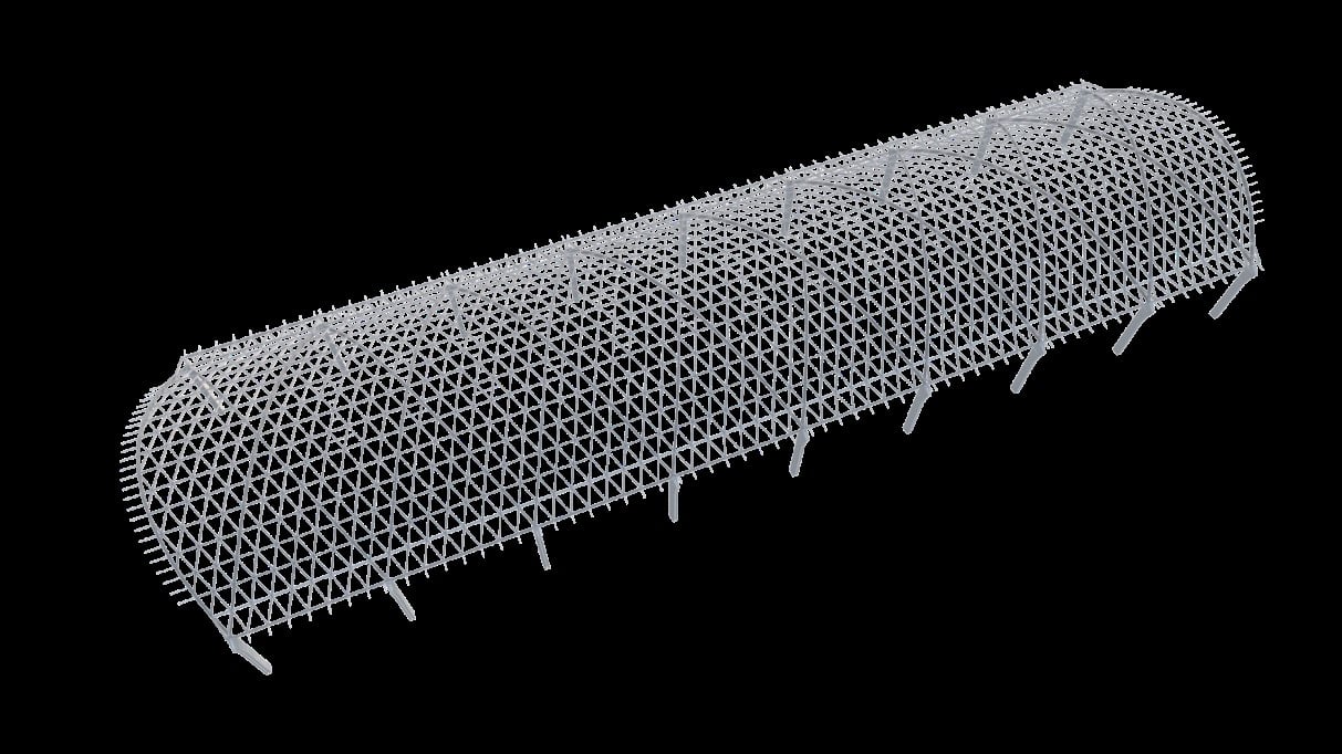
The roof structure has been designed as a single continuous structure without any movement joints. It is 280m long by 80m wide on plan, with a clear span of 70m over the station’s western concourse, where it’s maximum height is 15m. Figure 5 shows an isometric of the entire roof structure.
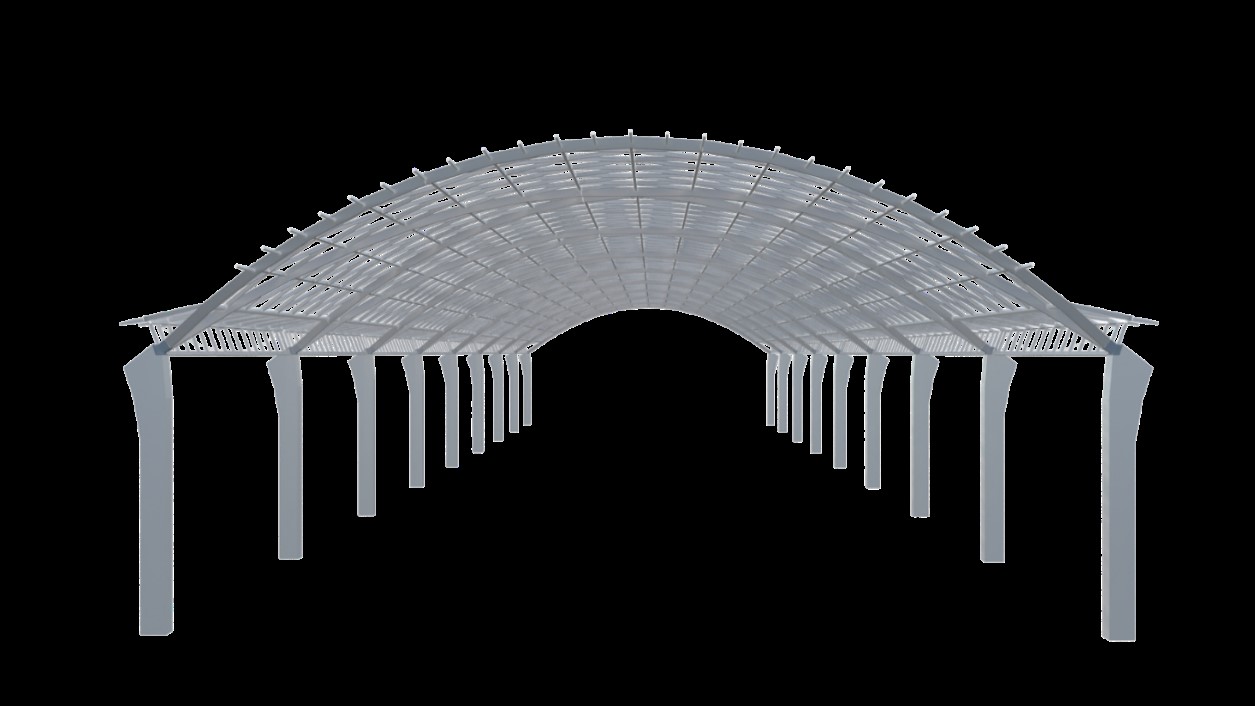
Figure 6 shows an elevation of the roof structure (concourse and viaduct level omitted for clarity).
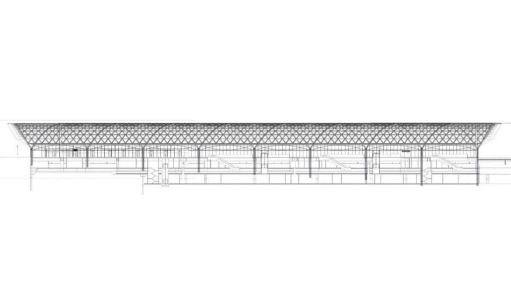
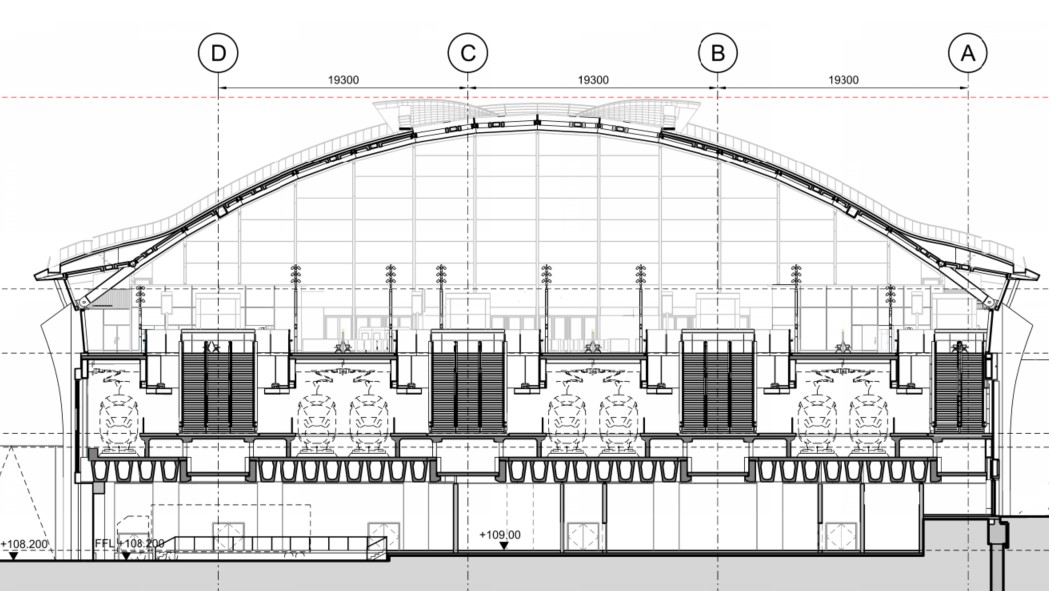
The relationship between the roof, concourse and platform levels below is shown in long and short section through the station in Figures 7 and 8 respectively.
Structural Design and Analysis
Roof Structure
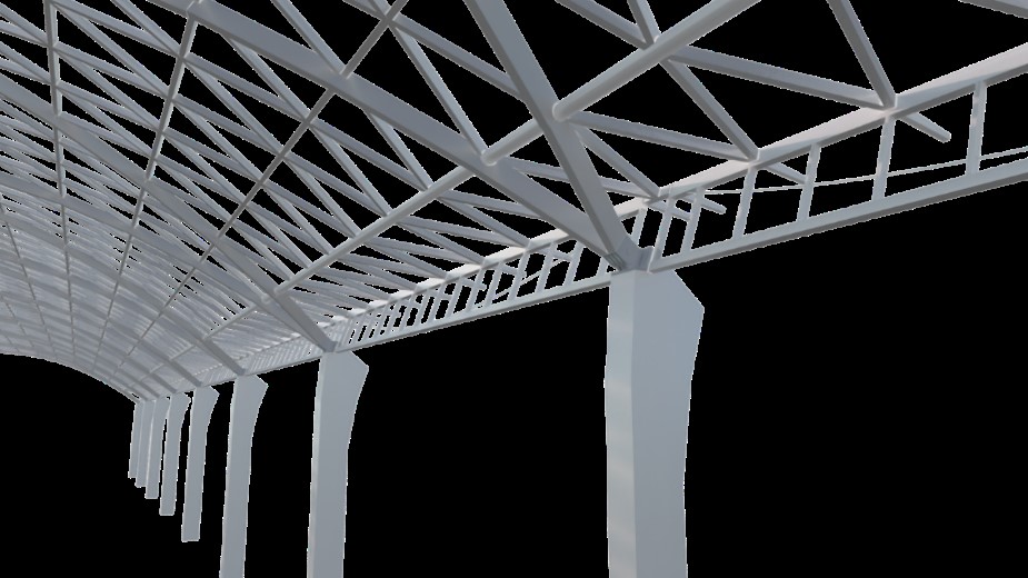
The roof structure consists of eight 32m long bays of a parabolic compression arch structure that spans across the full width of the station. The vault is tied via buttress columns by steel beams that also form part of the structure of the concourse, as shown in Figure 9, which displays the primary load paths of the roof structure. The structural components are illustrated in Figure 10.
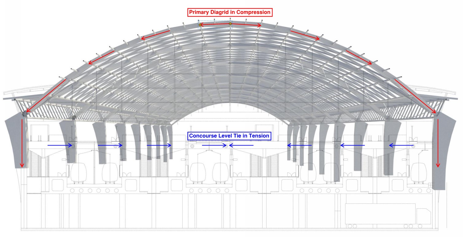
The roof comprises primary and secondary diagrid elements. The primary diagrid elements are a series of pin-ended elements that transfer the loads of the diagrid to the feature columns, whilst also stiffening the parabolic vault against global buckling.
Figure 11 displays the primary diagrid members (supported by the buttress columns and tied at concourse level).
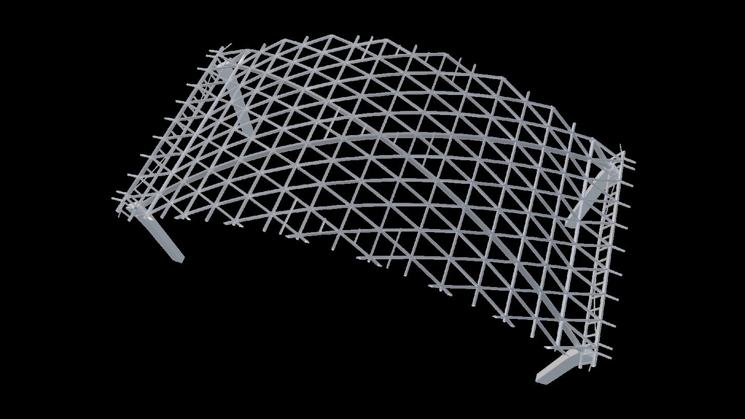
The secondary diagrid comprises additional pin-ended elements at 4m longitudinally and approximately 5m transversely to create 16 longitudinal rows of triangular bays. The triangulated diagrid of secondary members provides restraint to the primary ribs and to the secondary members themselves.
Figure 12 displays the secondary diagrid members.
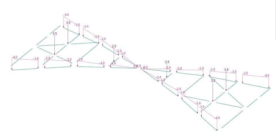
The roof structure supports glazed rooflights and roof smoke vent pods. The geometry of these structures was designed to align with the primary diagrid structure. Variable line loads from the pod structure and cladding, and point loads from the mechanical plant considered as part of the roof design are shown in Figure 13.
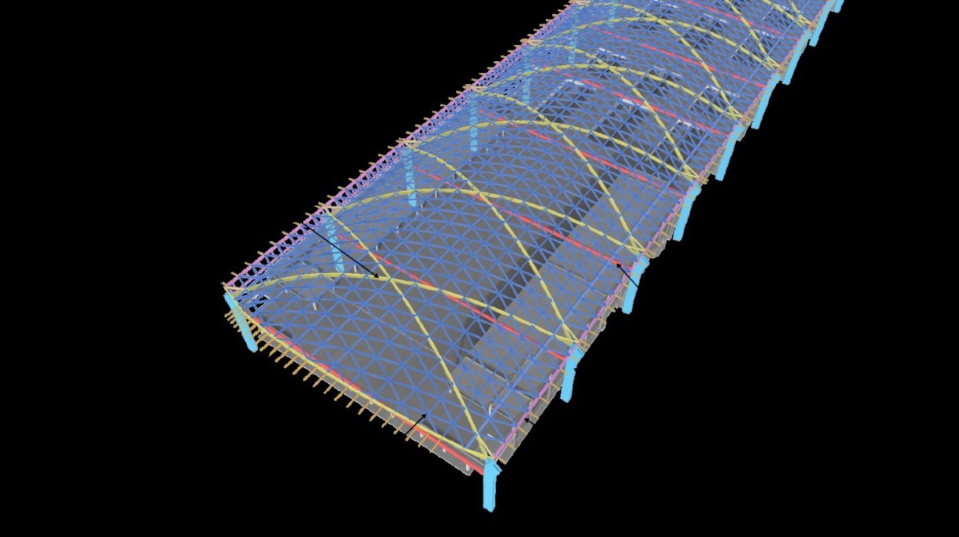
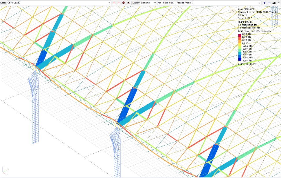
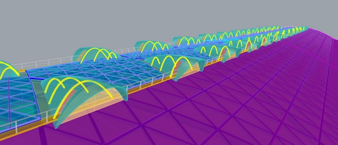
No restraint is provided by the roof deck system to the secondary beams. The diagrid elements are restrained laterally by the triangulated diagrid members as shown in the analysis output displayed in Figure 14.
The arched roof profile is raised at its eaves; the roof surface here is separated from the structural parabola that continues to the pin. This results in raised ‘wings’ along the length of the building.
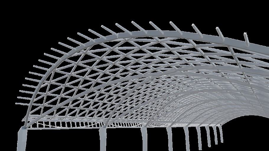
The secondary diagrid peels away from the primary diagrid in both edge bays to create the structure supporting the wings. The edge of the secondary diagrid is stiffened by a larger diameter CHS section and the edge of the roof is supported by cable-supported trusses, as shown in Figure 15.
This aspect of the design works twofold: in providing an added formal interest to a traditional station arch – particularly evident at the resultant double curved corners – and in providing a clerestory band of glazing along the full length of the western concourse.
At either gable end of the roof, tapered box sections cantilever approximately 3.5m beyond the last primary diagrid to support the overhanging roof as shown in Figure 16.
Buttress Column Structure
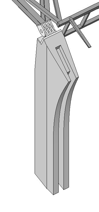
The roof is supported entirely by 18 reinforced concrete columns that are profiled as shown in Figure 17. These are arranged along the north and south edges of the roof at 32m centres and extend down to capping beams or pile caps on either side. A central 600mm recess extends down the outside face to incorporate the rainwater down pipes, which is displayed in Figure 18.
The columns act as buttresses and in bending to transfer the compression forces from the primary diagrid to ties at concourse level. These tie beams are fixed to the internal face of the buttress columns, as shown in Figure 19.
The buttress columns also provide support to the concourse level of the station building and take lateral restraint from the concourse and viaduct levels. They are fixed at their base connection to a capping beam or pile cap and act as vertical cantilevers to resist the lateral forces imparted to them by the roof and concourse levels.
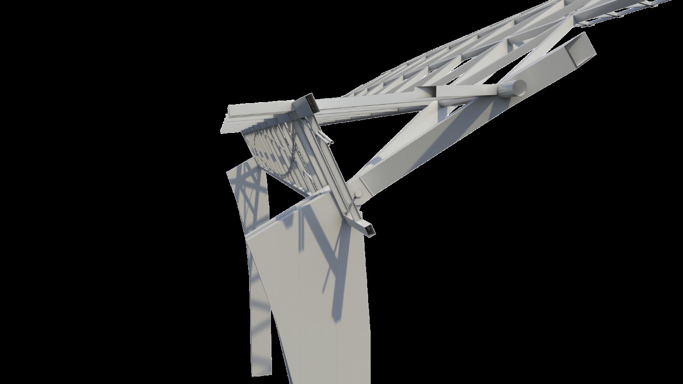
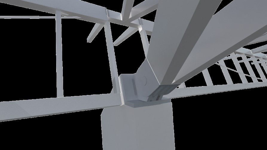
The pin and base plate detail, shown in Figure 20 is an important juncture in the design configuration: this is the point where the steel roof structure and primary concrete column connect. It is intended as a legible expression of the elegance of architectural engineering; an important theme in the proposed design for the station.
Design Considerations
The structural elements of the roof and buttress columns have been designed for a ‘design working life’ of 120 years, in accordance with Eurocode ‘Category 5’ buildings – as recommended in Table NA.2.1 of the UK National Annex to BS EN 1990:2002[1].
Due to the steelwork being difficult to access, the hollow section steelwork in the roof has been designed to be fabricated from Cor-Ten (or weathering) steel to maximise the design life for the predicted environmental conditions.
The roof structure is Consequence Class 3[2] and is therefore Execution Class 3. To satisfy the requirements of a Class 3 structure, the design included a key element removal design case inclusive of removal of a buttress column or structural tie in a catastrophic event.
The roof was modelled for linear elastic analysis using a single global model that represents the entirety of the steel structure above station concourse level.
The roof analysis model has a total of 282 load combinations of which several include positive and negative temperature load cases. The load combinations including temperature were not the governing combinations for the roof design. The roof members and connections have adequate capacity to resist the forces induced in the temperature combinations.
Forces are generated in the elements as the roof is subject to thermal loads and it expands and contracts. These forces are relatively small in comparison to the forces generated by other load cases. The roof analysis model incorporates the spring stiffnesses of the supporting columns, which act as slightly flexible supports rather than rigid pinned supports, and this helps to reduce the temperature related forces that build-up.
Designing the elements for axial forces due to thermal loads in combination was considered preferable to introducing movements joints for the following reasons:
- Splitting the structure with an internal movement joint would increase the overall steel tonnage whilst reducing the robustness of the roof.
- Movement joints would need to be detailed to accommodate the resulting movements and would be a weak point for water ingress.
- The structure would need to be doubled up at the movement joint and the movement joints themselves would be prominent and contrary to the intended soffit and façade treatment.
- Introducing non-continuity in the roof structure would result in more temporary works during construction.
Coordination with Architectural Design
Roof Cladding
The covering of the roof is a natural finish metal standing seam system. This is a lightweight, low maintenance covering that is suited to both the expanse and curvature of the roof arch. The metal roofing sheets are clipped to a structural metal deck using proprietary stainless-steel cleats with minimal offset.
At the eastern and western ends, the seams begin to taper after the last rooflight so that the final seam runs parallel to the ultra-high-performance concrete (UHPC) edge trim. This allows water from the overhanding roof section to be channelled back to the rainwater outlets without the need for a gutter or upstand detail on the eastern and western edges of the roof.
Roof Soffit
The warm timber soffit is comprised of 2m by 2.5m triangular soffit panels with composite steel / timber ‘picture frame border’ and timber batten cladding on aluminium mounting frame, as shown in Figure 21. The timber soffit extends beyond the western and eastern gable ends of the main station arch so will be visible externally.
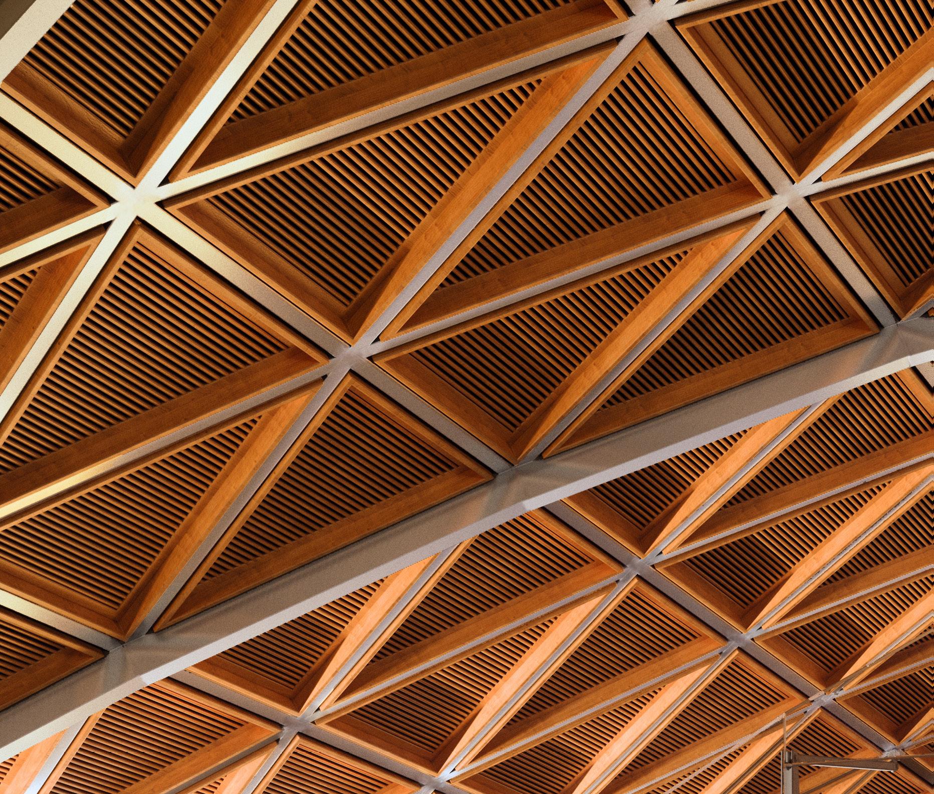
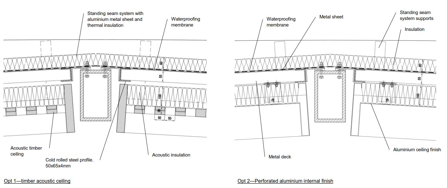
The structure comprises a cassette system with a pre-finished soffit, which fits within the triangular bays of the roof diagrid. The top surface is finished with Kalzip. There are currently two options for the roof cassette system, which are displayed in Figure 22.
Roof Perimeter Cladding
The perimeter roof fascia is a critical architectural feature incorporating a profile which combines the junction of the soffit, the gutter and the metal seam roof. At the corners of the roof the fascia connects the eaves and verge into a single compound curve comprising double curved panels, as shown in Figure 23.
Architecturally this sweeping curve of the building must be smooth and avoid a faceted construction; the panels comprise a mould formed cement composite, in a material called ‘ultra-high-performance concrete’ (UHPC).
The roof perimeter on each side (north/south/east/west) is finished by an eaves profile (north/south sides) or verge (east/west sides) profile formed in durable and smooth ultra-high-performance-concrete panels (UHPC). Bird roosting deterrent measures will be incorporated in to the UHPC profiles within a continuous recess at the roof perimeter.
This material represents the latest in concrete technology for construction, being thinner and stronger than glass fibre reinforced concrete (GFRC). The cladding is installed in large panel modules with a relatively joint-less appearance to give an overall impression of a monolithic surface.
Roof Pods and Roof Lights
Double glazed fixed roof lights run the full length of the western concourse block. These lights provide sky views and natural lighting.
The overall arrangements, shape and the modular dimensions of the roof lights are derived from the triangular geometry inherited from the diagrid structure. The roof light comprises a steel framed curtain wall with triangular double-glazed panels. The finish to the frames will be a light grey-white for contrast with the primary roof grid.
The rooflight framing is set above and spaced off the steel diagrid below, thereby allowing the two to be visually separated. Bird roosting deterrent measures will be incorporated at the top surface of the diagrid profiles throughout the glazed area.
The means of smoke ventilation for the station through the roof is a series of mechanically powered ventilation fans housed within UHPC-clad enclosures, located in the central field of the roof between adjacent hexagonal rooflights, as shown in Figure 24.
The ventilation pods are designed to visually relate to the form of the main station roof, as shown in Figure 25, but the form also provides a practical shape to allow drainage of the enclosure onto the main roof and to minimise wind resistance. The recessed face of the pods – the vent – has an outer perforate architectural screen providing protection to the access walkway and an inner louvred screen connected through internal ductwork to the ventilation fan assembly inside the pods.
Buttress Columns
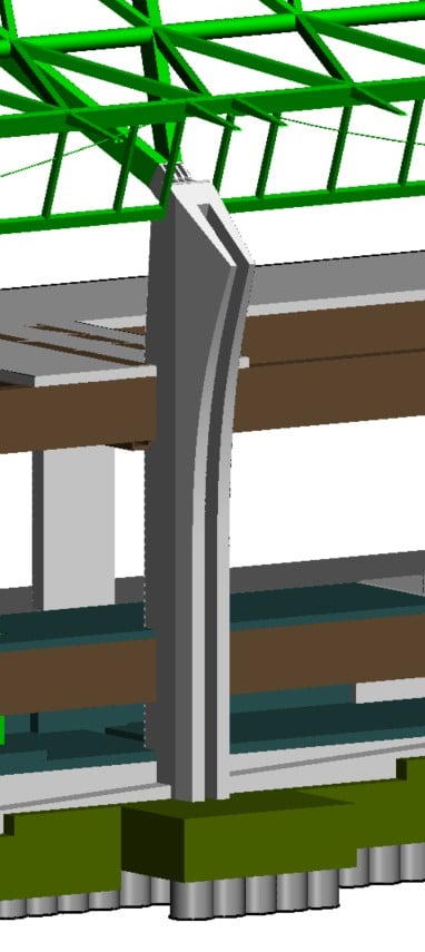
The primary roof structural columns, shown in Figure 26, are constructed in architectural quality reinforced in-situ concrete. The columns are tapered in plan moving away from the building to minimise their profile in respect of public realm. The downpipes, integrated into the outer face of the column profile, are expressed as architectural elements as they span between the underside of the soffit and the head of the roof piers.
Construction Sequencing
Constructability
As well as achieving a lightweight, elegant aesthetic, another aspect of the design brief was that safety ought to be at the forefront of the design approach. Therefore, it was determined that to minimise both the time spent working at height and conducting hot work (i.e. welding of connections etc.) the roof design needed to be modular to enable prefabrication of larger sections off site prior to on-site assembly. This increased the complexity of the design as it meant that, not only did the member arrangement have to achieve the requisite structural integrity within the slenderness constraints, it also had to do so in a manner suited to modular construction (i.e. forming a regular pattern of suitable size), as well as in a way that made the on-site connection of prefabricated sections quick and easy.
Owing to the constraints on member sizes, the structural arrangement was paramount in achieving the requisite structural integrity. Not only this, but with the onus on safety, the arrangement also had to facilitate assembly in the fewest number of lifts to minimise the level of risk on-site. This meant that the design of member supports and connections in particular would be critical and would necessitate extensive computational analysis in order to determine feasibility and to optimise their designs.
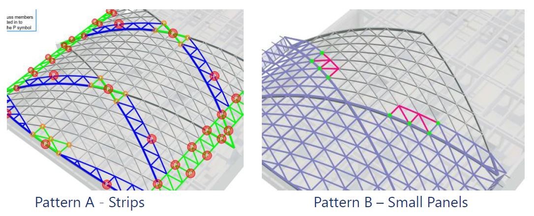
During the schematic design stage, numerous design options were explored to develop a solution that could satisfy the above criteria and in relation to the arrangement, various methods of pre-fabricating sections were considered, including strips and panelled sections of different sizes (Figure 27).
The options were assessed to determine the suitability of panel sizes for transportation, assembly within the required area on site and lifting. All these methods were fully explored and sequenced during this initial period of design evaluation, including appropriate temporary propping methods for each.
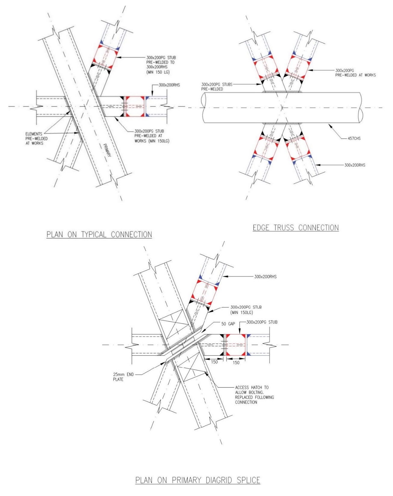
This method of fabrication will be developed at the next design stage alongside the contractor and will include analysis of the member supports and welded connections. In anticipation of this stage, selected in-depth computational analysis using Finite Element Analysis (FEA) was undertaken around some of these complex components (Figure 28), with some components going through a number of iterations to ensure the loads could be transferred and supported adequately.
Construction Options
For schematic design, a series of workshops were undertaken to develop temporary works options for constructing the roof. These will be developed alongside the Contractor at Detailed Design stage
. Three potential options were considered:
- Option 1 – A traditional method including high level platforms;
- Option 2 – An alternative method using discrete towers and props; and,
- Option 3 – An alternative method using a launched system.
Option 1
The use of high level temporary works platforms has been in use since the development of arches in the 2nd century BC and remained the dominant form of building arches through into the 1900’s, for example the construction of St. Pancras Station. This method continues to be used in modern construction, especially where access is required to install complex ceiling soffits and services at height, for example Berlin Central Station.
The proposed construction option comprises three to four bays of full width high level working platforms as shown in Figure 29, with steelwork supported on adjustable props off the working platform. The construction could progress from either end of the building or indeed both at the same time to converge at the middle of the structure. This system is simple, well-established and flexible, however, it is work intensive requiring multiple assembly and disassembly cycles which in themselves increase the risk to safety. In addition, this option requires the falswork to be supported off the concourse slab, restricting the possibility for other works to progress at concourse level during the construction of the roof.
Consideration was given to mounting the temporary works on movable bogies to reduce the need for full dismantling and hence the time of relocating the system for the next bay as the working area progresses. To maximise the utilisation of the temporary works, the ceiling installation could be progressed with the roof steelwork to provide a degree of weather protection for following works.
Option 2
An alternative method was considered, which takes advantage of the ability of prefabricated sections of the roof to span between discrete towers where they are connected to form the primary load-bearing frame (see Figure 28). Subsequent sections are then placed and connected to the primary frame to complete the roof. As in the traditional approach, the construction could be progressed from both ends of the station as in Option 1.
This method reduces the extent of the temporary works but does require works such as the secondary connections and soffit installation to be completed from Mobile Elevated Working Platforms (MEWPs). This is now one of the most common methods for assembly of large span roof members for example the Abu Dhabi Mid-Field Terminal.
This option reduces the amount of temporary works required in comparison to Option 1 and has the potential for programme advantage, depending on the amount of temporary propping required. As with Option 1, it is a simple construction method, but the discrete towers would improve the access arrangements at concourse level.
Option 3
A second alternative method was also considered. This option involves sliding the roof incrementally along the building as each roof bay is assembled. It comprises temporary works in the form of a fully decked working platform built in the first two western bays of the structure. The eastern two bays are then constructed using the working platform using the same propping arrangement use for Option 1. Installation of the roof covering and soffit would also be undertaken at the same time.
Once a bay has been assembled the roof is then slid along two guide rails running the length of the station building inside of the main roof feature columns to which they are secured. A proprietary roller system would be used to support the roof during moving with lateral arch springing loads resolved through the use of lateral rollers or a temporary cable tie between lateral support points.
This system is then repeated for the remaining bays with temporary jacks used to secure the roof between moves. Once the roof is in its final position the permanent pin jointed bearings will be installed and the permanent load transferred to the feature columns.
This method has been developed over the last 50 years in response to long span bridges and the demands of the offshore oil and gas industries and is now more common in civils and buildings construction, for example in the construction of Liege, Guillemins Station in Belgium. It has the advantage of reduced temporary works compared to Options 1 & 2 which would allow work to progress at concourse level between moves. However due to the novel and more complex nature of the method, there are associated risks which would require further development with the Contractor.
During this stage, the following limitations and areas for further development were identified:
- Means of traction – it is anticipated that hydraulic jacks could be used with either strand jacking principles, clamps onto the guide rail or jacking pins into the guide rail; or alternatively electric motors could be used.
- Means of providing arch stability at the trailing edges through the temporary works guide rail support system – it is anticipated that a vertical and horizontal roller system could be used.
- Deflections and monitoring regime – it is recognised that automated monitoring would be beneficial.
- Connection details on the permanent works to account for variations on build tolerances and how the temporary condition affects the permanent condition.
- Temporary works arrangement to support the guide rail and how this interfaces with the concourse structure and voids.
Constraints
In reviewing the options for assembling the Curzon Street Station roof, various site constraints were considered, including:
- The proximity of the Network Rail Rugby-Birmingham Stafford (RBS) line to the southern elevation;
- Lifting limits and reach of various crane options;
- Availability of laydown areas for delivery and preassembly of roof sections;
- The load capacity of the concourse and track bed structures to carry temporary loads;
- Impact of roof construction sequence and programme on following permanent works; and,
- Environmental Minimum Requirement limits on HGV movements on/off site.
Health & Safety
The construction of roofs on large buildings such as stations, airport terminals and arenas inevitably requires working at height. The use of modern lifting and access plant combined with the increased focus on health and safety in the planning and management of construction, have significantly improved the safety of working at height; however, risks remain and both designers and contractors should not become complacent.
The Health & Safety Executive report (Construction statistics in Great Britain 2019)[3] highlights the continued risk of working at height with 84% of all fatalities and 75% of all non-fatal accidents caused by situations which could occur during working at height as required for the assembly of the BCS roof.
Whilst the design endeavours to remove or minimise many of these risks, health and safety must continue to be at the forefront of the development of the roof construction methodology, the designers and HS2 operations teams.
Conclusions
The design of the Birmingham Curzon Street Station roof demonstrates innovation and efficiency, through the lightweight nature of the steelwork, developed through extensive research and analysis. It is envisaged that the new knowledge and capability generated through the development of this unique arched roof structure would be useful on future large-scale building projects where lightweight design and visual elegance are important aspects of the design specification.
Safety during construction was at the forefront of the design, with key risks eliminated through the modular design, such as hot works and working at height. This safety thinking can be applied to other projects from an early stage, to ensure that risks relating to construction are not considered too late to be able to eliminate them.
Successful collaboration and communication between architects and engineers has resulted in an elegant structure with integrated details, such as cladding and roof lights. This approach can be used on projects of all scales, to develop a coordinated design.
Additional technical papers are proposed to provide further detail on the following two aspects of the design: innovative and efficient design integration; and, the detailed structural design of the roof, including the material efficiency in comparison to similar structures elsewhere.
Acknowledgements
The WSP Birmingham Curzon Street Station multi-discipline design team who have contributed to the design of the roof and this report, including: Peter Chipchase and Dan Hagan (lead structural designers for the roof); Chris Hayter; Graham Evans; Max Fawcett, Neven Sidor and the team from Grimshaw Architects; and, Garry Murray and Marcus Birleson (Construction and Logistics team).
References
[1] BSI (2004). NA to BS EN 1990:2002+A1:2005. UK National Annex to Eurocode 0 Basis of structural design.
[2] BSI (2006). BS EN 1991-1-7:2006+A1:2014. Eurocode 1 – Actions on structures – Part 1-7: General actions – Accidental actions.
[3] Health and Safety Executive (2019). Construction statistics in Great Britain, [Accessed 2019].
Notation
BCS – Birmingham Curzon Street Station
FEA – Finite Element Analysis
GFRC – Glass fibre reinforced concrete
HS – High Speed
HS2 – High Speed 2
MEWPs – Mobile Elevated Working Platforms
RBS – Rugby-Birmingham-Stafford
UHPC – Ultra-high-performance-concrete
Peer review
- Hala Lloyd, Lead Architect (Curzon)HS2 Ltd
- Jiten Davdra, Head of Engineering and Environment (Stations)HS2 Ltd