Chiltern Tunnel cross passage durability design – response to challenges
The High Speed Two (HS2) Chiltern Tunnel will contain 40 cross passages (CPs), 38 of which are mined tunnels based on sprayed concrete lining (SCL) design. The Chiltern Tunnel and its cross passages are required to have a design life of 120 years, befitting of a structure of national significance. The 38 SCL cross passages play an important role in the safe operation of the tunnel, thus a robust durability design is crucial in preventing early deterioration of the structural lining which would generate unwanted maintenance, operational disruption and increased maintenance costs for the tunnel.
This paper details the cross passage durability design measures implemented in order to achieve the 120-year design life. It also highlights the challenges faced in designing the cross passages to meet HS2 watertightness requirements including locations which have up to 40 metres of groundwater pressure head. Cross passage durability design involved an integrated system comprising of several lines of defence from the external water pressure, these include a waterproofing system and secondary lining crack width of 0.2 mm. A robust waterproofing system comprising of a compartmentalised PVC sheet membrane was designed to encase the cross passages as the first line of waterproofing. The secondary line of waterproofing is the cast-in-situ concrete lining. The cross passages also contain a water management system comprising of drainage channels at either sides of the invert and the provision of a drip tray at the TBM running tunnel junction to manage potential water ingress.
This paper also details the durability measures implemented for the cast-in-situ secondary lining including a specified 0.2mm external face crack width limit, adhering to HS2 requirements. Focus will be on durability design in accordance with client requirements and industry best practice.
- Written by
-
Thomas Schultheis

- Resource type
- Resource type: Technical Paper
- Tags
- Cross Passages posts
- Durability posts
- SCL posts
- waterproofing posts
Introduction
Durability design is becoming an ever more important requirement within the design process for infrastructure projects. Stringent durability and other related technical requirements are being made mandatory by clients. This puts emphasis on the Designer to overcome project specific challenges by developing designs which meet the requirements and satisfy the specified design life of the asset and its individual elements.
Project and Cross Passage Description
The Chiltern Tunnels are part of the central section of High Speed Two (HS2) Phase One – Lot C1 – which also includes the Colne Valley Viaduct, being delivered by the ALIGN Integrated Project Team.
Section C1 comprises the 16km long Chiltern Tunnel. From south to north, this twin bored tunnel will pass underneath the M25 and a section of the Chiltern Hills including the village and towns of Chalfont St Peter, Chalfont St Giles, Amersham, Little Missenden and the edge of Chesham.
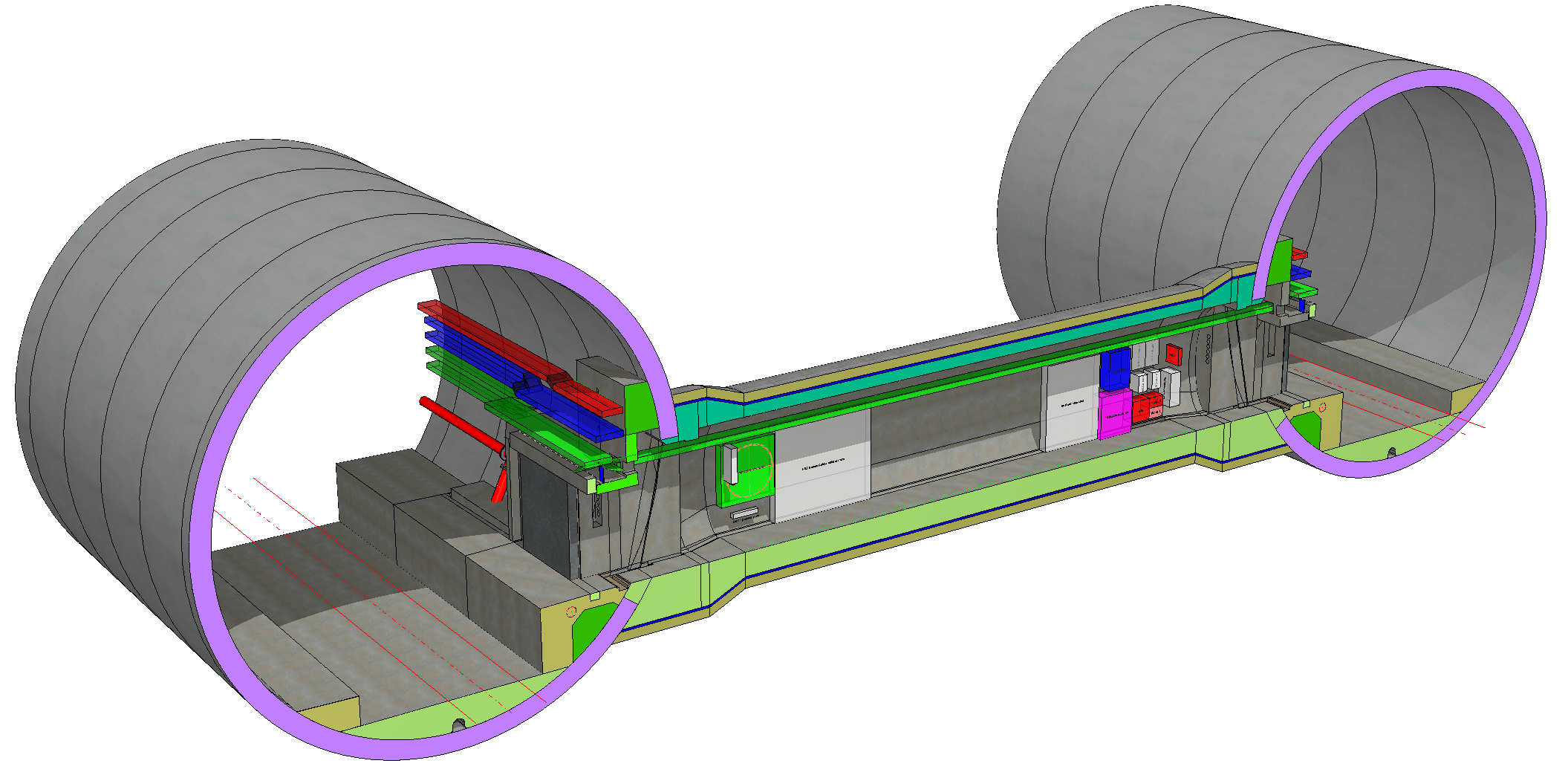
The tunnel scheme will consist of 40 cross passages (CPs), of which 38 are mined tunnels based on sprayed concrete lining (SCL) design. These CPs will be spaced approximately 500m along the tunnel alignment connecting both the Up line and Down line tunnels and are required to provide a means of emergency escape from the incident tunnel to the non-incident tunnel. CPs also house permanently fixed rail systems equipment.
Cross passages will be excavated from the main TBM tunnel and consist of a steel-fibre reinforced (SFR) sprayed concrete primary lining and SFR cast in-situ concrete secondary lining with a sheet membrane waterproofing system between the two linings. The cross passage waterproofing will be a fully tanked system, completely sealing the cross passage against ingress of groundwater. This system provides a high level of protection to the tunnel, aiding durability. At the cross passage openings, a conventionally reinforced concrete collar will be constructed.
Cross passages are underground structures which are integral to tunnel operations and are critical with respect to durability and watertightness requirements. Watertightness is critical for protecting the CPs from groundwater ingress which would affect the mechanical and electrical rail systems equipment housed in the CP. A waterproofing system ensures protection of the CP secondary lining concrete against potentially aggressive groundwater. Cross passages are considered to have the following classifications in accordance with BS EN 1990 [4]:
- Consequence Class CC3
- Reliability Class RC3
- Design Supervision Level DSL3
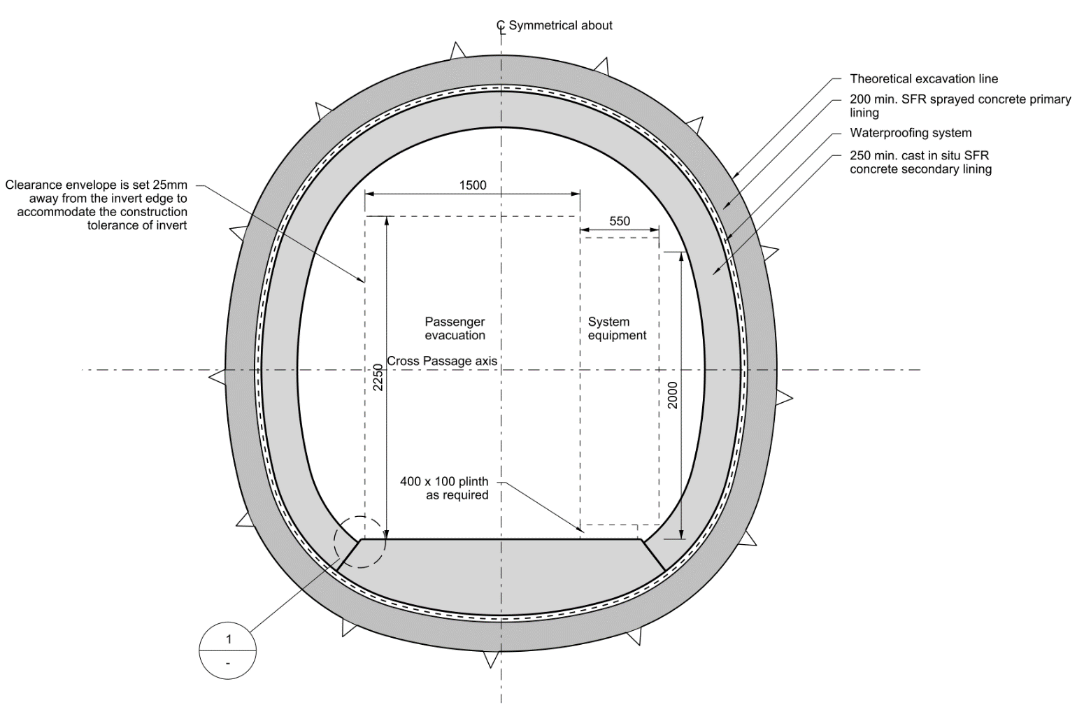
A single type of cross section profile consisting of 200mm SFR sprayed concrete primary lining and 250mm SFR cast in-situ concrete secondary lining has been designed for all the cross passages except two CPs which are located in a high-risk fault zone. In these two CPs conventional reinforcement was specified for the secondary lining. The standard cross section is shown in Figure 2.
At the ends of CPs where they interface with the TBM tunnels, an enlarged cross section profile for the excavation and primary lining has been developed. This will accommodate the breakout opening on the TBM lining and the waterproofing system termination details. The termination detail establishes the waterproofing interface between the sheet membrane system of the cross passage and the TBM segmental lining.
A reinforced concrete collar will be constructed inside the TBM tunnel around the opening and be structurally connected to the TBM lining segments to transfer the load around the opening for both permanent and temporary conditions.
Geological Setting affecting Durability
In order to design a durable structure, the environmental conditions the structure will be subjected to over the course of its design life needs to be carefully studied and understood. An understanding of the geological and hydrogeological setting is essential for underground structures.
The Chiltern Tunnel is to be constructed through the Chiltern hills which, at the alignment depth, primarily comprises of Cretaceous White Chalk. The challenges to designing durable tunnels within Chalk is its property of being a porous rock. The engineering behaviour of Chalk is governed by the presence and characteristic of discontinuities. These discontinuities promote higher groundwater flow rates and, in some areas, the discontinuities are enlarged by solution weathering which can result in extremely high flow rates.
The River Misbourne is the only significant watercourse along the route with the tunnels crossing beneath the river in two places at project chainage 35+400 and 42+200. At these two river crossings, the CPs will encounter highly weathered Dc/Dm structureless Chalk [15] and a water head of 16m and 24m respectively (measured to the tunnel axis). The CPs will be in very high permeability zone with a coefficient of permeability (k) greater than or equal to 1×10-05 m/s.
Groundwater levels were established from a hydrogeological study and modelling which culminated in various design levels. Most cross passages will be constructed under the water table. The highest groundwater level for the tunnel alignment expected for the 120-year design life, including the effects caused by climate change, were used in the design of the cross passages.
The cross passages will encounter water heads ranging from a minimum of 2m at Ch. 32+730 south of Chalfont St Peter Shaft, to a maximum of approximately 40m at Ch. 40+775 near the Amersham Shaft. The maximum water head coincides with the highest overburden height of approximately 74m, which combined, provides the most onerous load case for CP design.
HS2 durability requirements
A HS2 Technical Standard dedicated to specifying requirements for materials and durability was applied to the design of the Chiltern Tunnel[9]. There are many applicable requirements for CP design, however, for the purpose of this paper the major influencing requirements will be discussed including watertightness criteria and concrete crack width limits.
All permanent work elements in the cross passages have been assessed as ‘critical’, in line with the HS2 Materials and Durability requirements, including the secondary lining and waterproofing system which shall be designed to a design life of 120 years.
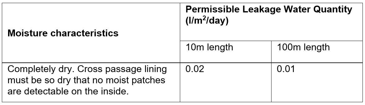
HS2 have specified that the maximum concrete crack width shall be restricted to 0.2 mm or less for elements requiring watertightness unless there are two independent water management measures consistent with the specific watertightness and durability criteria. HS2 have specified watertightness criteria[10], which are based on international best practice for rail tunnels, stating that cross passages must meet the highest level of watertightness as listed in Table 1.
Cross passage junctions with running tunnels have a separate watertightness criterion with a maximum permissible flow of 1 l/m2/day per junction after implementation of measures to prevent water ingress. These measures include re-injection of grout tubes around the junction and resin injection of cracks.
Durability design is affected by climate change and changes in long-term groundwater levels have the greatest impact on the design of underground structures. A specific requirement is for an additional 5mm concrete cover to reinforcement. This is mandatory within the parameter ‘additive safety element ![]() ’ which exceeds the UK National Annex to BS EN 1992-1-1 [6] recommending
’ which exceeds the UK National Annex to BS EN 1992-1-1 [6] recommending ![]() is taken as 0 mm. As concrete cover is one of the primary means of designing for durability, an increase of 5mm due to climate change effects is a conservative approach.
is taken as 0 mm. As concrete cover is one of the primary means of designing for durability, an increase of 5mm due to climate change effects is a conservative approach.
HS2 tunnel operational requirements indicate short overnight engineering maintenance periods to take place which will mean limited availability to access the cross passages, thereby reducing the opportunities to effectively undertake visual inspections and maintenance. This excludes unplanned maintenance intervention which is required for emergency inspections and repairs. As such, the design must take into account that time consuming maintenance activities such as concrete repairs will not be achievable during such short maintenance periods.
Environment and exposure conditions
The ground environment and expected internal tunnel environment were extensively studied during the durability design process as these are crucial in the design and specification of the CP concrete secondary lining and sheet membrane waterproofing.
Ground Environment
Based on site-wide information, the ground environment has an Aggressive Chemical Environment for Concrete Classification (ACEC class) of AC-1 and a Design Chemical class of DC-1, both being the lowest class for their respective classifications[7]. These denote that the ground is benign and non-aggressive.
Due to the close proximity of the M25 at the London end of the tunnel, the presence of hydrocarbons was tested in the groundwater. Hydrocarbons have the potential to adversely affect the durability of polymers, including the cross passage waterproofing system sheet membrane and its various polymer-based components. Evaluation concluded that the presence of hydrocarbons is limited and will not impose a significant contamination risk. Therefore, special consideration is not required for specification of the waterproofing system materials.
Chlorides increase the risk of reinforcement corrosion which impacts durability of the tunnel’s concrete elements including cross passage lining and TBM segmental lining. Groundwater testing was performed for chlorides which concluded that the tunnel is located outside the influence zone of chloride de-icing salts from the M25 and other local roads along the alignment. As the CPs have a concrete chloride class of 0.4, in line with BS 8500-1, it is considered chlorides will have no detrimental impact on the CP lining.
Most cross passages are located entirely below the groundwater level, except towards the south and north portals where the structures rise above the groundwater table. This naturally leads to the extreme parts of the structure being located within a zone of intermittent saturation where groundwater surrounds the tunnels temporarily and risks these CPs subjected to a cyclical wet and dry process. This process is known to accelerate the ingress of groundwater chemicals into the concrete. During the drying stage, groundwater chemical agents can concentrate on the concrete surface. To mitigate against this risk, the concrete will be designed against a XC3/XC4 exposure class[7].
Internal Environment
All cross passages are located underground between the two running tunnel bores and are considered a tunnel environment.
Temperatures within the Chiltern Tunnel and cross passages will exceed an annual average of 20°C within the design life. Summer tunnel temperatures were assumed to transition from approximately outside conditions at the tunnel entry portal to typically 35°C but may reach up to 40°C in the central zone and exit portals. Winter temperatures were assumed to transition from approximately outside ambient conditions at the tunnel entry portal to 30°C at the tunnel exit portal[1][11].
Carbon dioxide (CO2) limits within the tunnel during operation, considering climate change affects, are not expected to exceed 760 ppm [1][11], which is a limit beyond which increases the risk of carbonation of concrete structures and requires special deterioration assessments [9]. Therefore, the cross passage concrete lining will not have an increased risk of carbonation.
Tunnel relative humidity is assumed to vary between 30% to 50% during summer and 20% to 30% during winter[1][11]. Carbonation of concrete is known to be affected by relative humidity [19], although this affect is negligible for relative humidity below 50% or above 98%. Temperature is generally thought not to affect the rate of carbonation[16]. Therefore, the anticipated tunnel operational maximum relative humidity of 50% falls within a range where carbonation rates will be negligible. The appropriate concrete exposure class for the internal environment will be XC3.
Cross passage durability design
This section will focus on the cross passage durability enhancement measures implemented in the design including waterproofing system and concrete design. Consideration of waterproofing detailing, concrete cover, crack limits and use of steel fibre reinforcement will be discussed. Durability enhancement measures made in concrete mix specification and construction workmanship will not be discussed in this paper.
The cross passages will incorporate two independent waterproofing measures in order to achieve HS2 watertightness and durability requirements. These waterproofing measures include:
1. A waterproofing system comprising of:
(i) Waterproofing membrane and a min. 700 g/m2 geotextile fleece
(ii) Compartments formed by water barriers which allow repair grouting
2. Concrete secondary lining with 0.2 mm external face crack width
The CPs will have a slope on the finished floor level and a drainage channel along each side as an additional water management measure to transfer any water to the main TBM drainage system, preventing water pooling. Drainage channels mitigate against water accumulations which would lead to deterioration of other parts of the concrete lining and rail systems equipment.
Waterproofing System
Cross passage waterproofing system consists of a sheet membrane positioned between the SCL primary and cast in-situ concrete secondary lining and incorporates compartmentalisation established by water barriers welded to the waterproofing membrane and cast in the cast-in-situ concrete. The waterproofing system will not be accessible for replacement therefore it has a HS2 design life requirement of 120 years.
The sheet membrane will consist of soft Polyvinyl Chloride (PVC) of approximately 2mm thickness (including signal layer). This system will create a continuous impermeable heat-welded unreinforced waterproof membrane encasing the cross passages. A non-woven geotextile fleece, of at least 700 g/m2, will protect the sheet waterproofing membrane against penetration by the potentially rough surface of the primary lining and provide a water flow path for water around the cross passage. The presence of hydrocarbons within the groundwater is limited therefore this does not affect the selection of a PVC membrane.
The PVC membrane was chosen as it is a highly reliable waterproofing option that has been successfully proven to achieve its intended purpose on many related SCL tunnels on other UK and international infrastructure projects for more than 50 years. PVC is a durable material that is guaranteed by the waterproofing manufacturer for the design life of 120 years. Major waterproofing manufacturers have demonstrated through accelerated ageing testing that, PVC waterproofing membranes are durable for 100 plus years. PVC membranes extracted from tunnels built in the 1960s and 1970s were shown to have little or no deterioration[3].
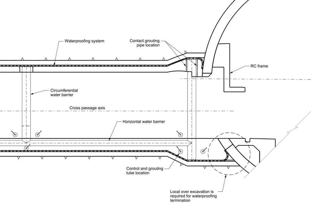
The CP waterproofing system will be compartmentalised, which is achieved by the placement of PVC water barriers fully welded to the sheet membrane on one side. The ribs on the other side of the water barriers will be cast in the concrete lining. Each compartment will be the length of a secondary lining pour (maximum 10m) and each length will be longitudinally divided into two compartments at the location of the interface between the invert and crown concrete. All compartments will have grouting ports connected to repair tubes (control and grouting tubes). Sika AF 4-ribbed water bars 310mm wide will form compartments within the waterproofing system as shown in Figure 3.
Compartmentalisation allows for grouting, using an appropriate resin, of specific compartments displaying leakages post-installation if a breach of the waterproofing membrane would occur. This is a proven and effective method for repairing any defects within the waterproofing system.
The waterproofing design and membrane specification have taken into account long term ground and structure movements, changes in the groundwater level and potential changes in material elongation due to environmental factors including oxidation, microbiological degradation and chemical exposure. The membrane is prescribed to be flexible at low temperatures and provide high resistance to puncture, high water pressure and is weldable. Resistance to high water pressure is critical as some CPs will be expected to be subjected to up to 40m water head over the 120-year design life. The waterproofing system, including water barriers and grout hoses, has been designed to sustain a maximum water head of 40m identified near the Amersham shaft section of the tunnel.
Not only must the waterproofing sheet membrane be durable for the 120 years, but all other components that make up the complete waterproofing system must have a service lifetime of 120 years, including the water barriers, grout hoses and connections, construction adhesives, etc.
During the durability design process, a risk assessment was performed on the potential deterioration and failure mechanisms of the waterproofing system’s materials. It was identified that environmental stress cracking (ESC), the brittle failure of polymers exposed to stress and a surfactant[12], was the most likely failure mechanism for PVC waterproofing membrane with a ‘possible’ likelihood. Failure of the waterproofing system would lead to groundwater flow into the cross passage affecting rail systems equipment and other internal CP fit out elements. This failure can impact tunnel operations and increase maintenance interventions. All these consequences have serious effects on the durability of the cross passages, although the overall risk from ESC was deemed low.
Smaller components within the waterproofing system were also subject of a risk assessment as deterioration or failure of these can impact other components. For example, if water barriers fail, the compartmentalisation can be compromised and leaks cannot be localised or confined to one compartment. To mitigate against this risk, cross passages will rely on the second line of defence from water pressure which is the secondary lining concrete design.
Secondary Lining Concrete Design
The secondary lining is the main permanent structural support element of the cross passages which resists long-term earth pressure, groundwater pressure and surcharge loads throughout the design life. Structural analysis determined all cross passages required a minimum 250mm thick secondary lining reinforced with steel fibres to resist all design loads.
The secondary lining is considered a second water barrier with the aim of inhibiting groundwater ingress in the event of breaches in the waterproofing system (primary measure). It is a critical element which requires a design life of 120 years as maintenance intervention to undertake lining concrete repairs will not be effective during the expected short maintenance periods.
The secondary lining extrados will be in contact with the waterproofing membrane and potential groundwater in the event of a breach of the waterproofing membrane. The intrados is exposed to the internal atmospheric conditions of the individual tunnel cross passage. The primary deterioration mechanism which risks secondary lining durability is carbonation. Secondary lining extrados is not accessible for visual inspection and/or repair while the intrados will be accessible for inspection, monitoring and maintenance but only during limited planned engineering possessions of the tunnel.
The sprayed concrete primary lining is a temporary element which is to stabilise the ground during the construction period, providing support until the permanent secondary lining is installed. The primary lining has no permanent support function.
Steel fibre reinforcement
The secondary lining will consist of cast-in-situ, steel fibre reinforced concrete (SFRC) Class C35/45 with added polypropylene microfibres for improved fire resistance.
SFRC was analysed as being capable of providing the required capacity for the ground and groundwater loading conditions. SFRC was also chosen for its durability advantages over conventional reinforced concrete. Literature have reported that due to steel fibres being non-continuous within the concrete, they do not support the mechanism for propagation of corrosion between fibres and that steel fibre corrosion is less active compared to steel bar reinforcement [20]. Steel fibres also improve concrete crack control as the cracks are better dispersed and hence smaller than that compared with conventional bar reinforcement.
It is expected that steel fibres at the surface of the concrete will corrode over the design life but only at the depth of carbonation in an uncracked section[13] [14]. This leaves the interior fibres isolated and protected from corrosion from the chemical properties of the cement paste. Due to their small size, the volume increase of corroded fibres will not generate concrete spalling.
Crack width
The secondary lining has been designed with a maximum crack width of 0.2mm for the external face (extrados). This crack width limit will reduce the rate of groundwater penetration in the event of a breach in the waterproofing system. Limiting the crack width to 0.2mm allows for the potential autogenous healing of the concrete[2], particularly where CPs are subjected to a low water pressure gradient.
Concrete cover
In addition to the concrete cover requirements applied from BS 8500 Parts 1 and 2, the cross passages containing conventional reinforcement in the secondary lining will have an increased concrete cover taking account the effects of climate change. The additive safety element ![]() for climate change impact is +5 mm to minimum cover in accordance with HS2 Durability Technical Standard.
for climate change impact is +5 mm to minimum cover in accordance with HS2 Durability Technical Standard.
Termination Detail
A design challenge involved the detailing of the waterproofing system at the interface with the TBM running tunnel to ensure HS2 watertightness criteria was met. The most sensitive part of any waterproofing system is the interface detail with another structure. For the Chiltern Tunnel’s 38 cross passages, it is critical that the waterproofing termination detail at the interface with the running tunnels is carefully designed with the characteristics of the waterproofing system of both structures in mind. The cross passages are designed with a sheet membrane waterproofing system while the running tunnels are lined with a single-shell, segmental lining support. The waterproofing system in the segmentally lined running tunnels is provided by the high-quality watertight concrete segments, while gaskets in the joints between the segments provide barriers to the inhibit groundwater inflow. If problems arise from a poorly designed termination detail, it has the potential to create a significant durability problem for all 38 CPs.
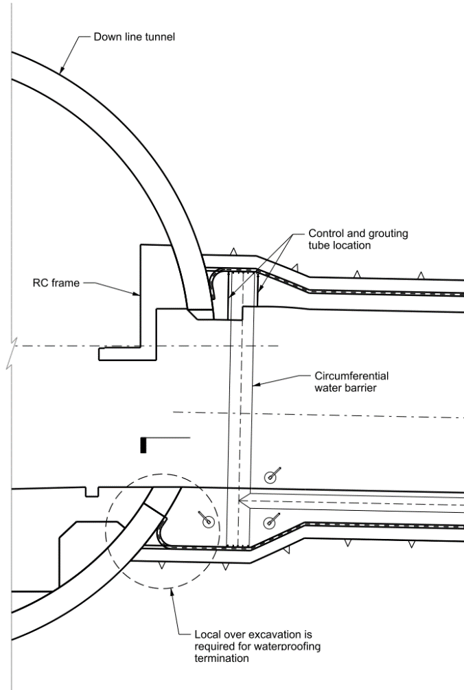
The cross passage and TBM running tunnel designers identified the best ways for detailing the waterproofing interface including functioning at a 40 m water head. At the ends of CPs where they interface with the TBM tunnels, an enlarged cross section profile has been developed. The cross passage sprayed primary lining will interface the TBM segmental lining. A fillet of the primary lining internal face will provide a curved profile for the waterproofing system.
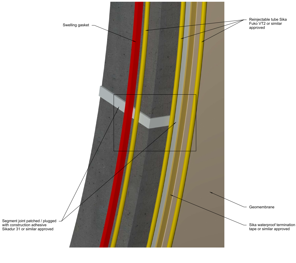
The entire circumference of the termination detail at CP openings will comprise of a series of re-injectable grout tubes positioned around the opening on the extrados of the TBM segmental lining providing multiple barriers against potential water ingress. The re-injectable grout tubes, which are specified as Sika Fuko VT2, are located at three locations including: the membrane before the termination, after the termination detail (bonded on the Sikadur 31) and a third position on the radial joint of the segmental lining which is offset from a swelling gasket as shown in Figure 5. Fuko VT2 re-injectable tubes are specified to ensure repair grouting is possible under high water head. Offset from the termination detail is a circumferential water barrier.
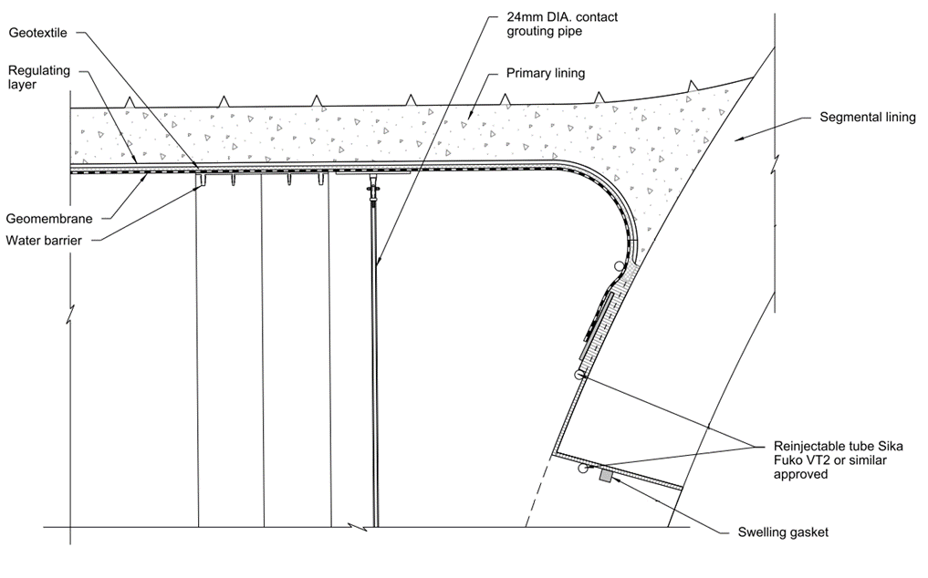
The waterproofing membrane will be continuously hand welded to a waterproofing termination tape which is bonded to a construction adhesive, such as Sikadur 31, applied to the segmental lining substrate. For this termination detail to be effective, the groove to the extrados of the segmental lining EPDM gasket joint will be injected with the Sikadur 31 resin, filling the joint completely. This is to prevent water inflow along the joints between the segments at the interface.
The design includes a provision for a drip tray which can be installed at the cross passage / running tunnels junction as a water management measure if leakages cannot be stopped by grouting through the re-injectable grout tubes. The steel drip tray, which will follow the profile of the CP opening, diverts potential seepage water into drainage channels either side of the CP invert and connects into the main running tunnels drainage system. The drip tray can be accessed and be maintained from within the CP.
The above measures provide two lines of waterproofing measures at the cross passage and TBM tunnels interface and are designed to meet the HS2 watertightness criteria. The waterproofing membrane and re-injectable tubes form one line, while the secondary lining concrete forms the second line of defence. The drips trays are an additional water management measure to be used if the two waterproofing measures fail.
Recommendations
Early coordination with other disciplines is critical for provision of data and/or interpretation of data relating to durability input and design. Some examples of interfaces with other disciplines for data includes:
- Hydrogeological modelling of groundwater levels over the 120-year design life including climate change effects. This depends on the ground investigation programme for groundwater monitoring results.
- Groundwater testing and chemical analyses for influencing parameters such as pH, sulphates, chloride content, hydrocarbons, and other contaminants.
- Coordination with tunnel ventilation team for parameters on the tunnel operational temperatures and humidity ranges forecast for the design life.
It is important that roles and responsibilities for durability design are defined early for seamless design progress and avoidance of overlapping and duplicated work. This is particularly important in large infrastructure projects where several design consultants and multi-disciplinary teams work within a design joint venture. A core team of durability engineers are required to oversee the durability design of all assets so that it is treated as a whole system. An organisational chart of the roles and disciplines provides understanding of team setup and who to approach for provision of information for durability design.
A durability planning process ensures the right information is gathered, analysed, and implemented in a logical manner that is efficient for project design programmes. For example, early work by the hydrogeological team to establish long term groundwater levels enabled the tunnels team to efficiently perform tunnel lining design at the critical periods of the design process.
With climate change as an important issue for the world, engineers are now on the forefront of designing structures which are required to be durable for a long design life, extending into a future where the climate will be different. It is important that engineers have the right knowledge and skills to incorporate climate change factors within their designs. For the Chiltern Tunnel design, this included taking account of changes to groundwater levels and temperature and humidity levels in the operational tunnel environment. It is also important that engineers are skilled in the correct application of climate change measures when designing concrete structures, such as increased concrete cover. It is recommended that the industry further addresses the upskilling of engineers for the durability design of structures considering climate change factors.
Conclusion
To achieve a 120-year design life and meet HS2 watertightness criteria, the Chiltern Tunnel cross passages were designed to contain a compartmentalised sheet membrane waterproofing system and a SFRC secondary lining with 0.2mm external crack width limit.
Challenges were overcome in providing waterproofing measures at the cross passage interface with the running tunnels, including precise waterproofing termination detailing, re-injectable grout tubes and a provision for drip tray installation for water management in case of a breach in the waterproofing system.
Durability is not only a design consideration but should be seen as a whole of life issue that starts with client requirements and progresses into various project lifecycle stages including design, construction, operation and maintenance.
Acknowledgements
The Authors would like to acknowledge and thank the Align JV for which the development of the Chiltern tunnel cross passage design was aided by contribution from a large multi-disciplinary team. The Authors would like to also thank Dr. Kurt Zeidler, Principal of Gall Zeidler Consultants, for his technical input and review of the text.
References
| Reference Title | |
|---|---|
| [1] | Align JV Report – Structures Durability Assessment Report (Document no: 1MC05-ALJ-ST-REP-C001-600031) (unpublished) |
| [2] | Bamforth, PB (2018) CIRIA C766 – Control of Cracking Caused by Restrained Deformation in Concrete. CIRIA, London, UK. |
| [3] | Beer HA., Eckl M. and Bonnet,M (2018) Testing durability of PVC membranes. (accessed on 12 June 2020) |
| [4] | BSI (2002) BS EN 1990:2002. Basis of Structural Design. BSI, London, UK. |
| [5] | BSI (2004) BS EN 1992-1-1:2004. Eurocode 2: Design of concrete structures — Part 1-1: General rules and rules for buildings. BSI, London, UK. |
| [6] | BSI (2004) NA to BS EN 1992-1-1:2004 UK National Annex to Eurocode 2: Design of concrete structures — Part 1-1: General rules and rules for buildings. BSI, London, UK. |
| [7] | BSI (2015) BS 8500-1:2015+A1:2016. Concrete – Complementary British Standard to BS EN 206 – Part 1: Method of specifying and guidance for the specifier. BSI, London, UK. |
| [8] | HS2 Specification for Civil Engineering Works Series 4060: Tunnelling – Waterproofing HS2-HS2-CV-SPE-000-014060 (unpublished) |
| [9] | HS2 Technical Standard – Materials and Durability (Document No. HS2-HS2-CV-STD-000-000003) (unpublished) |
| [10] | HS2 Technical Standard – Mined Tunnels and Associated Structures (Document No. HS2-HS2-TN-STD-000-000003) (unpublished) |
| [11] | HS2 Technical Standard – Shaft and Portal Buildings MWCC and Rail Systems Interfaces (Document No. HS2-HS2-CV-STD-000-000008) (unpublished) |
| [12] | Jansen J. (2015) Plastic Failure Through Environmental Stress Cracking. Plastics Engineering, November/December 2015 edition. (accessed on 20 July 2020) |
| [13] | King, MR and Adler, AJ. The practical specification of steel fibre reinforced concrete (SFRC) for tunnel linings (2001), Proceedings of Underground Construction 2001 Conference. Brintex Ltd, London, UK. |
| [14] | Lambrechts, A et al. (2003) Durability of steel fibre reinforced concrete, In Proceedings of the sixth CANMET/ACI durability of concrete conference SP212, ACI, Michigan. |
| [15] | Lord JA, Clayton CRI and Mortimore RN (2002) CIRIA Report C574 – Engineering in Chalk. CIRIA, London, UK. |
| [16] | Quillin, K, (2001) BRE Report 434 – Modelling degradation processes affecting concrete. BRE, UK. |
| [17] | The British Tunnelling Society and The Institution of Civil Engineers (2004) Tunnel Lining Design Guide. Thomas Telford, London, UK. |
| [18] | The British Tunnelling Society and The Institution of Civil Engineers (2010) Specification for Tunnelling Third Edition. Thomas Telford, London, UK. |
| [19] | The Concrete Society (2004) Technical Report No. 61 – Enhancing Reinforced Concrete Durability. The Concrete Society, Camberley, UK. |
| [20] | The Concrete Society (2007) Technical Report No. 63 – Guidance for the Design of Steel-Fibre-Reinforced Concrete. The Concrete Society, Camberley, UK. |
| [21] | Yu CW. and Bull JW (2006) Durability of Materials and Structures in Building and Civil Engineering. Whittles Publishing, Dunbeath, Caithness, Scotland, UK. |
Notation
| Abbreviation | Description |
|---|---|
|
BIM |
Building information management |
|
CO2 |
Carbon dioxide |
|
CP |
Cross passage |
|
EPDM |
Ethylene propylene diene monomer rubber |
|
ESC |
Environmental stress cracking |
|
HS2 | High Speed Two |
|
PVC |
Soft polyvinyl chloride |
|
SCL |
Sprayed concrete lining |
|
SFRC |
Steel fibre reinforced concrete |
|
TBM |
Tunnel boring machine |
|
XC3/4 |
Concrete exposure class with carbonation as the main deterioration mechanism |
Peer review
- Colin Rawlings, Lead Tunnel EngineerHS2 Ltd