Design of Chiltern Tunnel and ventilation shaft interfaces
The Chiltern Tunnel will be the longest tunnel on Phase One of High Speed Two (HS2). As part of the safety systems it is necessary to be able to provide forced ventilation for smoke control as well as intervention access for emergency services. As a result, five shafts are required along the alignment of the tunnel. In order to solve the challenge of making a connection between the bored running tunnels and these shafts, the Align JV have adapted an innovative design from a recent Bouygues tunnel in Cairo. It results in the HS2 Chiltern tunnel intercepting four circular shafts formed by diaphragm walls. This avoids the need to construct connections in difficult ground conditions, up to 70m underground. Ventilation requirements impose a very significant opening in the 9.1m ID tunnel. Two service apertures are also required from both sides of the ventilation opening. Tunnels need to be supported temporarily during construction stages and permanently.
For temporary purposes and water ingress management, it is proposed that the ground is treated all around the tunnels. Steel frames will be installed inside the tunnel to reduce the tunnel ovalisation and support the hoop force at the cut segments. To form the permanent junctions, non-standard hybrid segments reinforced with both steel fibres and conventional rebars, are locally installed around the opening. Concrete corbels will also be constructed to permanently sustain the tunnels at the enormous opening.
Two and three-dimensional sequenced models have been developed to demonstrate the overall functioning of the interface, define the stress concentration at the connection and control the displacements of the structures.
The aim of the paper is to present the sequence of works and design challenges encountered to justify the connections at all construction stages.
- Written by
-
Rosemary Lamand

-
Hala Sahnoun (Align/Bouygues Travaux Publics)

- Resource type
- Resource type: Technical Paper
- Tags
- 3D reinforcement posts
- corbels posts
- FEM modelling posts
- reinforced concrete posts
- SFRC posts
- Shafts posts
- Structural modelling posts
- Support frame posts
- TBM posts
- Tunnelling posts
- waterproofing posts
Introduction
The Chiltern Tunnels are part of the central section of High Speed Two (HS2) Phase One – Lot C1 – which also includes the Colne Valley Viaduct, being delivered by the ALIGN Integrated Project Team.
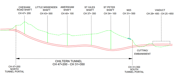
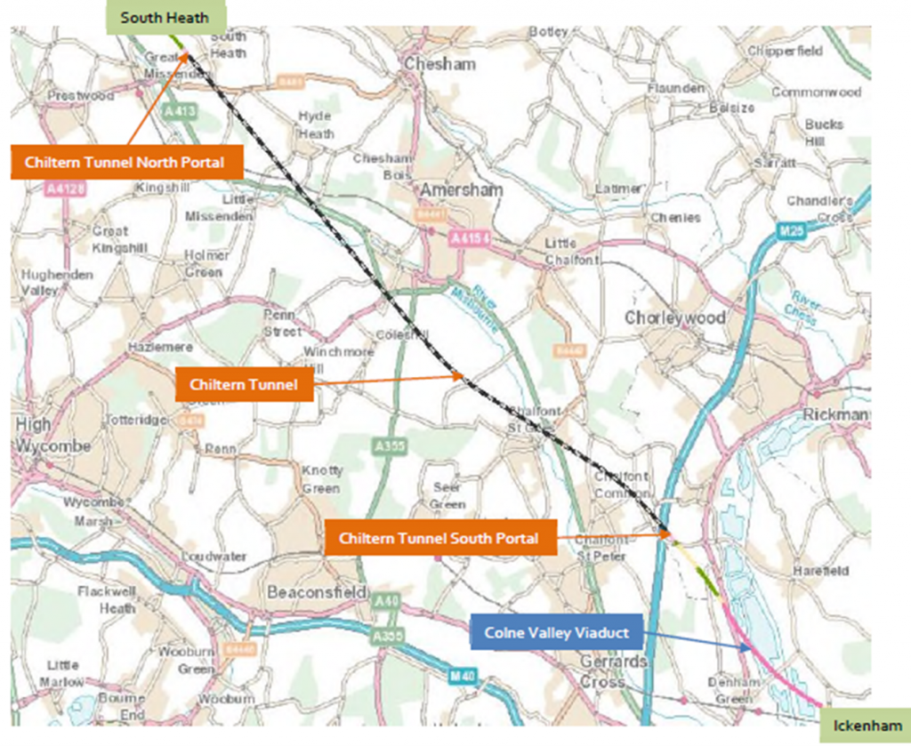
The C1 route commences with a 3.4km viaduct over the Colne Valley heading to a tunnel portal close to the M25 motorway. The twin bored tunnels are 16km long crossing under the Chiltern Hills. They start at the Chiltern Tunnel South Portal, heading north. A schematic of the route is shown in figure 1 below and a map of the route in figure 2.
There are 40 cross passages, of which 38 are mined, spaced along the tunnel alignment connecting both the north and southbound tunnels. These cross passages are required to provide a means of escape from the incident tunnel to the non-incident tunnel that is deemed to be as a place of relative safety. They also fulfil a function in providing a location for the rail systems permanently fixed equipment.
The contract also includes 5 intermediate shafts distributed along the TBM tunnels namely Chalfont St Peter Shaft, Chalfont St Giles Shaft, Amersham Shaft, Little Missenden Shaft and Chesham Road Shaft. The tunnels directly cross 4 out of 5 shafts and are connected to all of them via connection adits for ventilation and services continuity purposes. The tunnels surface within the Chilterns Area in the north portal.
One of the most challenging tasks in this project is the design of the interfaces between concrete structures specially the junction tunnel/shafts. Indeed, to avoid the need for more connection adits, it was preferred that the tunnels directly cross four of the five circular shafts, which represents a complex interface allowing for a large ventilation opening and side service apertures.
This paper will mainly tackle the design challenges, construction methods and calculation methodology regarding the design of these connections from a tunnel point of view.
Geometrical assumptions
TBM Tunnels
The TBM Tunnels will be excavated using variable density TBM with Earth Pressure Balance (EPB) and slurry-supported mode to continuously adapt the mode to the changing ground. It is a 16km-long twin tunnel of 9.1m internal diameter. The axis to axis distance is mostly 25m but is reduced to 17m at the end of the alignment. The tunnels follow a sinuous route, both horizontally and vertically.
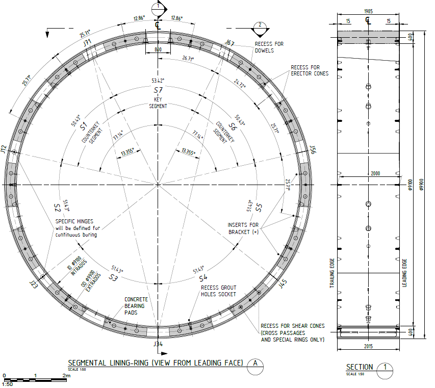
The Chiltern tunnels are mainly composed of fibre reinforced universal rings[3] comprising seven precast segments of a length of 2.0m and a thickness of 0.4m – see figure 3.
Some special segments reinforced with both fibres and conventional rebars will be installed at CPs, Adits and shaft junctions as well as at some fault locations.
The tunnel segments are equipped with intrados and extrados EPDM gaskets constituting two independent water barriers ensuring the tunnel watertightness, as well as several inserts including shearcones, dowels, sockets and guiding rods.
Shaft and tunnel/Shaft connection geometry
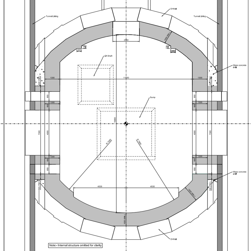
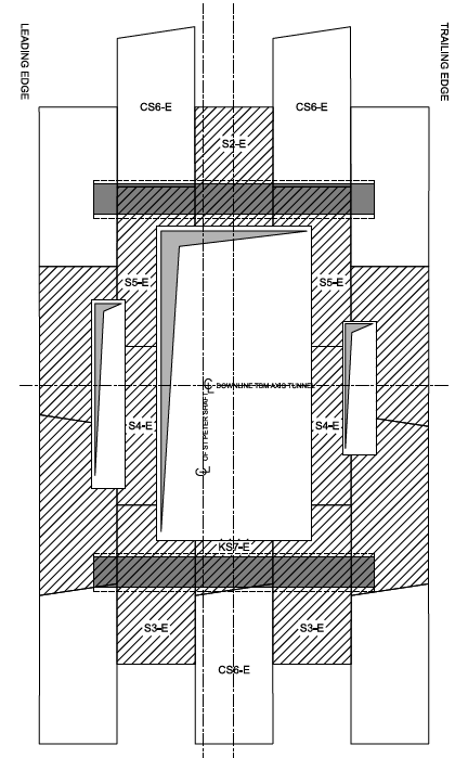
The shafts are formed of 1.2m thick Dwall panels, with a depth varying between 35 and 60m depending on the shaft location. The base RC slab and the shaft openings are supported by minimum 1.5m thick RC concrete collars – see figure 4. The inside of the D-wall has a waterproof layer applied to it prior to the installation of a 0.6m thick cast in-situ RC internal liner. The Dwalls have been designed to carry the full earth and water pressure loadings. Due to its construction, the D-wall is assumed to allow passage of water through the joints between the D-wall panels. Thus, the SFRC internal liner is designed to carry only the full water pressure. However, due to the waterproofing layer between the D-wall and internal liner, these two elements are considered to act structurally independently of each other for design purposes. Four blade columns are expected to be constructed at the tunnel/shaft intersection to provide the support to the collar beams.
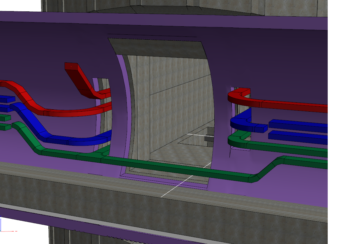
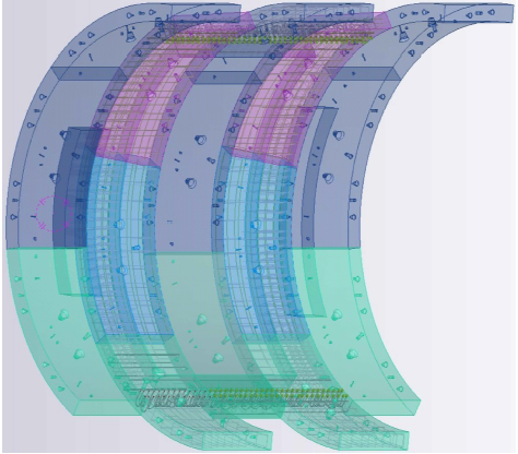
At each Tunnel/shaft intersection, three openings are made in the lining. One to allow for a ventilation aperture, which is the largest of the htree and is about 5m high and 4m wide, and two service openings for cables of 4 to 5 metres of height. A 3D illustration of the intersection is presented in figure 5 below.
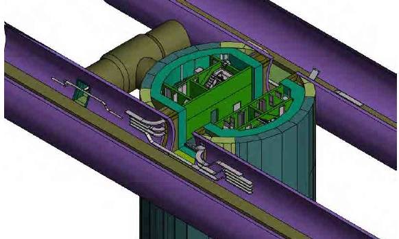
The excavation through the shaft Dwall and the three significantly large openings through the tunnels, require the design of a specific support system to guarantee the structural stability of both the shaft and the tunnel lining.
As mentioned, the shaft will be supported by an internal reinforced concrete tympanum cast inside the D-walls. This tympanum will be protruding inside the tunnels via corbels that aim to support the cut segments at the permanent stage.
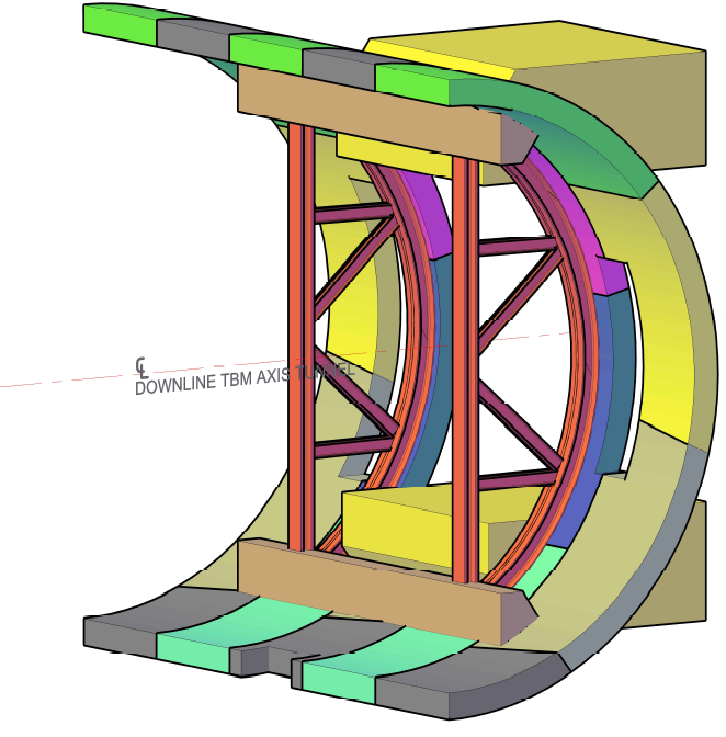
Due to the protrusion of the corbels, and the need to respect the openings permanent dimensions, the lining will have to be opened larger during construction with a 7m-high cut.
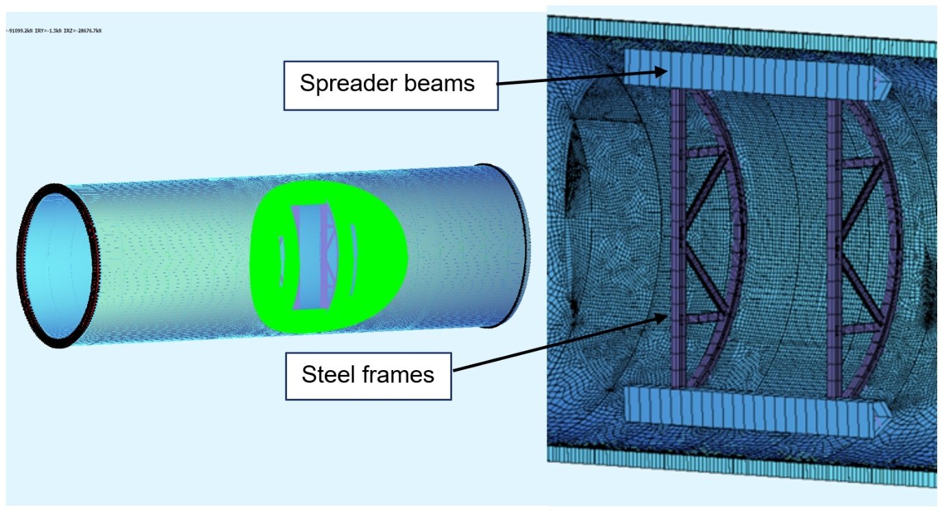
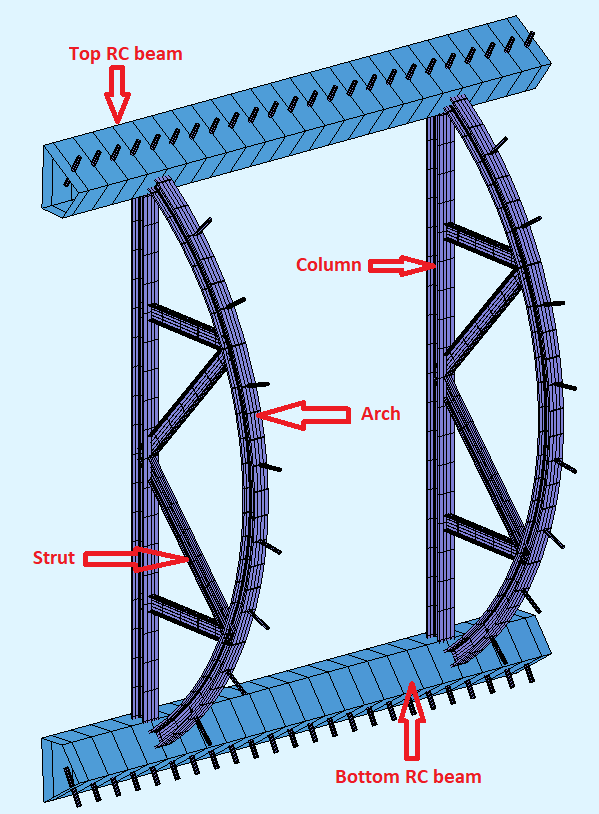
To support this opening during construction, a mix of concrete beams, steel columns and arch ribs will be installed in the tunnel prior to cutting the lining as shown in figure 6 below. The concrete beams are connected to the lining through couplers and post-drilled bars, and the steel frame is fixed using anchors.
Geological context
The geology of the Chiltern Hills is primarily composed of White Chalk overlain in some locations by head, alluvium, clay-with-flints and fluvial gravel deposits.
The Chiltern tunnels will almost exclusively be excavated within the Cretaceous chalk except for the portal areas where soil formations could be encountered due to the reduced overburden and more pronounced effect of weathering.
Soil and unconsolidated sediments encountered at tunnel portals, and above the chalk in specific locations along the alignment, consist mainly of alluviums, which will be typically encountered in valleys, head of variable composition and variable thickness between 2 and 8m, and Clay-with-Flints which is a residual deposit consisting of stiff to very stiff reddish-brown clay with flints.
The majority of the alignment crosses chalk, which is generally a white, ultra-fine-grained calcium carbonate limestone. The encountered chalk can be divided into different behavior classes based upon different criteria influencing its engineering properties. These criteria include strength and hardness, discontinuity spacing and pattern and discontinuity aperture and is known as the CIRIA classification (CIRIA 574)-[5].
The ground and water overburdens vary all along the alignment, the minimum ground cover being 7m and going up to 87m. The water cover is a maximum of 25m in the short term but is expected to reach 35m in 120 years. Some sections of the alignment are below the water table, mainly at the break-in and break-out.
Construction stages
Ground treatment
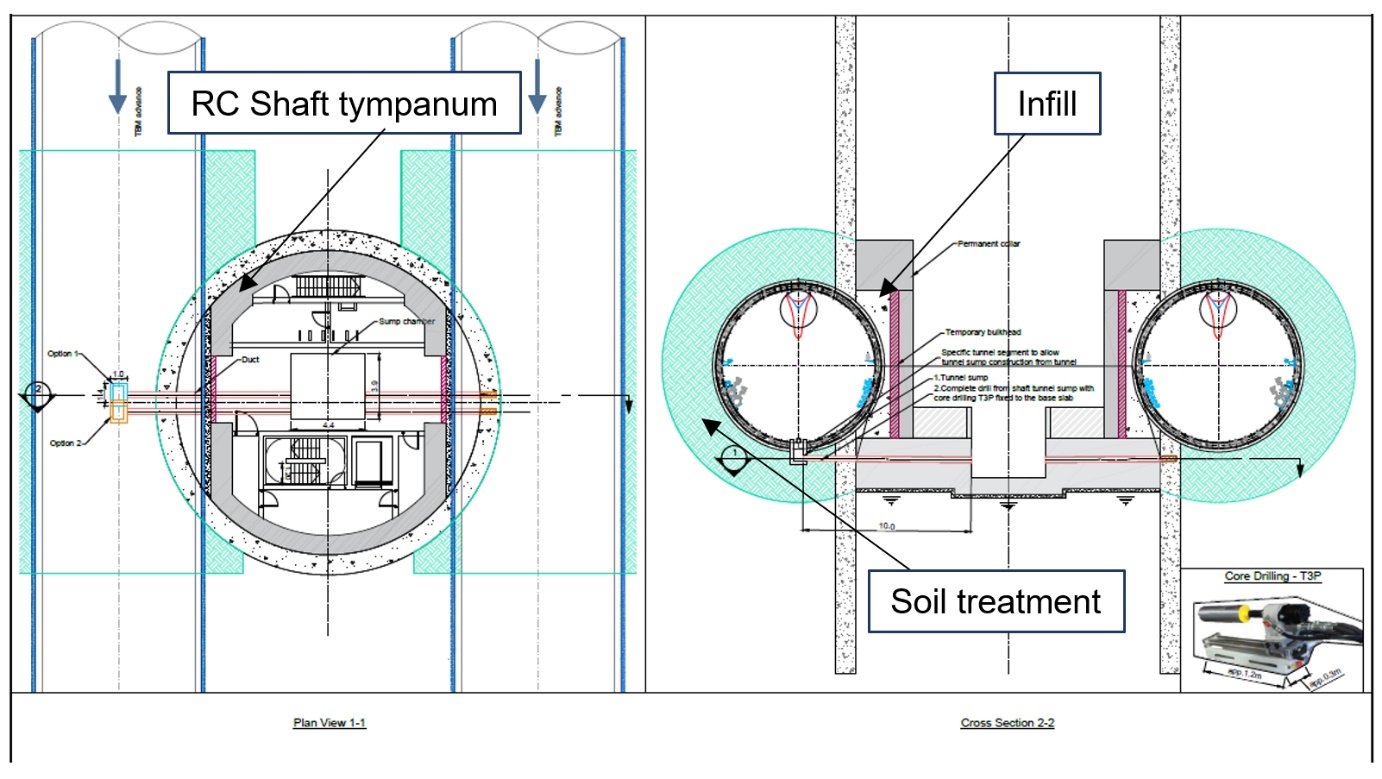
A circular ground treatment is first performed at the location of the interface from the shaft Dwalls already in place – see Figure 6. This treatment aims at lowering the permeability of the ground at the tunnel/shaft junction, to have a waterproof interface before the excavation of tunnel and the construction of the openings. No ground parameters enhancement is taken into account in the design.
Shaft collar construction
Once the ground treatment is in place, the shaft internal tympanum will be built according to a specific shape, leaving space for an infill material at the interface that is later excavated by the TBM. The tympanum is reinforced concrete, and the infill material is a low resistance concrete.
Tunnel excavation
The TBM goes through the shaft breaking part of the Dwalls and the infill concrete. The shaft structures are designed to resist the loads exerted on them by the TBM which include the TBM face and grout pressures as it cuts the shaft as well as the cutter head force. Once the tunnel is in place, the shaft also undergoes the ground horizontal loading transferred to it via the tunnel.
Opening construction
The construction of the openings through the tunnel lining follows a specific sequence of works particularly designed to minimise as much as possible the loads to be withstood by the lining at each stage in order to reduce the breadth of the temporary support.
Once the tunnel has gone through, the concrete beams are cast and the steel arch ribs and columns are installed. Then the infill material is removed in the upper part of the central opening before cutting the upper part of the central segments. Once this is done, the upper concrete corbel is constructed and then the remaining Infill is removed in the middle and lower part of the future ventilation opening prior to cutting the segments. As soon as the segments are opened, the bottom corbel is cast.
Afterwards, the infill is removed behind each of the future service apertures and part of it replaced by structural concrete prior to opening the segment. Finally, the steel frame is dismantled.
Design methodology
The design of the connection is based on three key governing factors: ground strength, overburden and water head. The design is made for the deepest shaft namely Saint Peter, thus the most loaded connection. This section only concerns the design of the temporary support composed of the concrete beams and the steel frame as well as the design of the special tunnel segments at the interface. It aims at presenting and explaining the modelling and structural checks undertaken for both the frame and the lining. The shafts collars and corbels design is excluded from this paper.
Soil structure interaction modeling
The cast in situ concrete beams and arch ribs aims at supporting the tunnel opening during the construction stages. It is designed to withstand the ovalisation and the hoop force transferred from the tunnel ring during the opening’s construction. Therefore, a soil-structure interaction analysis is led to evaluate the efforts in the lining resulting from soil and water loading.
The interaction between the tunnels and their environment is complex, often three-dimensional, and highly nonlinear due to the elasto-plastic behaviour of the surrounding soils. The Convergence – Confinement Method[4] provides a convenient way to bring this 3D problem to a two-dimensional one through the use of a stress release ratio. This method has been successfully validated by experience on numerous tunnels.
The tunnel lining calculation is therefore made with a global (effective) stress release factor λ* which includes the confinement effect of the TBM pressure and is carefully determined so as to be more conservative towards the internal efforts in the tunnel lining.
The Soil structure analysis is performed using “Plaxis 2D” software. The concrete lining is modelled as an elastic plate using the Muir-Wood[6] formula to calculate the inertia of the segmental lining. The surrounding ground is modelled using the Mohr-Coulomb elastic perfectly plastic law and considered drained, except for clayey layers that are modelled using Hardening soil model and considered undrained.
The SSI modelling gives the inner forces on the lining, namely the axial forces N, bending moment M, and shear force Q. These forces are given for three different stages; the short term when the soil treatment is still effective which leads to lower loading on the tunnel, the medium term when the water loading goes back to normal, and the long term when the water table is at its highest expected level.
Structural modeling
The inner forces stated above constitute the initial state of the ring before being cut.
When the ring is cut to create the openings, these forces have to be transferred to the adjacent rings by the use of the upper and lower concrete beams and the rings joint capacity (mainly friction with the adjacent rings). The arch ribs and columns help ease the ring ovalisation and bending.
The opening in the lining changes the repartition of the forces which loads the temporary support. Load transfer between structures happens thanks to the couplers and post drilled bars connecting the beams with the lining and the anchors connection the columns and arch ribs to both the beams and to the lining to reach a monolithic behaviour of the combined structures.
The structural design of the temporary support and special segments is performed using a 3D plate model on Sofistik software. The model represents the frame including the concrete beams, the steel columns and arches as well as the tunnel segmental lining with the shear cones and dowels at the orthoradial joints, and bedding support representing the ground, the shaft Dwalls, the infill material, and the corbels. The tunnel is loaded so as to reproduce the inner forces given by the soil structure interaction analysis at short, medium and long term.
Support frame design checks
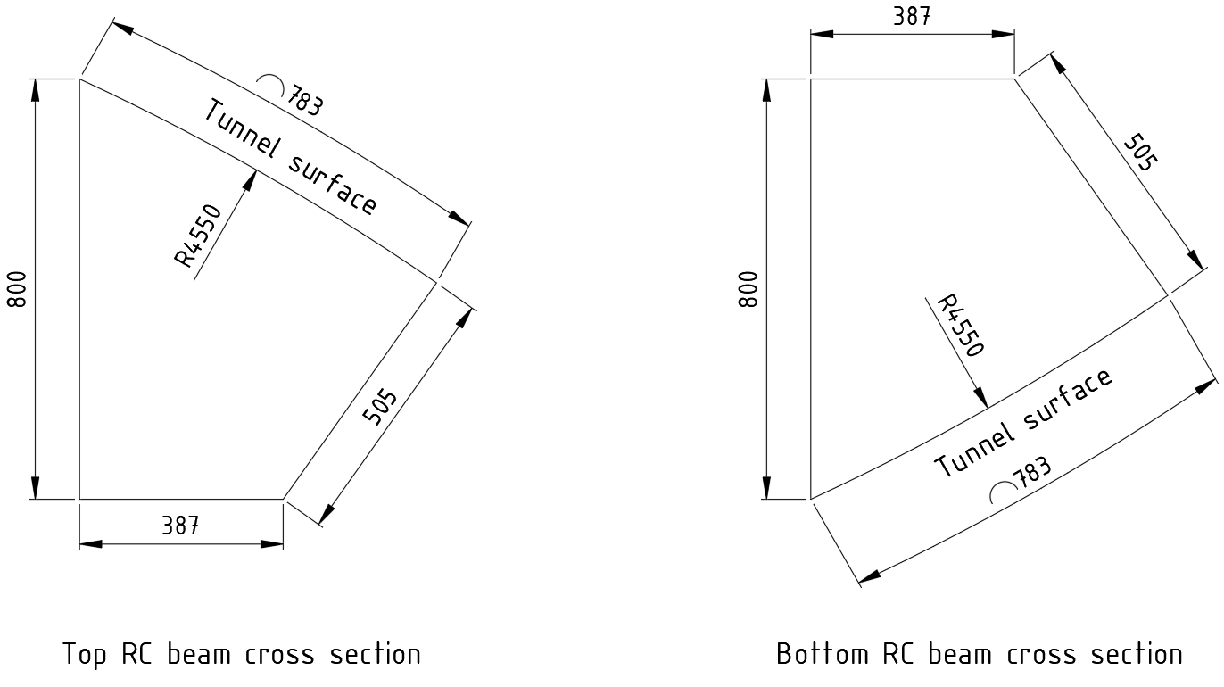
The spreader concrete beams are conventionally reinforced. They are approximatively 800m height and 500mm thick. They help transmit the hoop force from the cut segments to adjacent tunnel rings. They are designed based on BS EN 1992-1-1[1]. Checks regarding compound bending, shear and torsion are undertaken .They are performed for ultimate, service and accidental limit states.
Due to the large opening, the beams undergo bending and very high shear efforts and are therefore subjected to tension forces, which therefore requires a high amount of flexural reinforcement. Shear combined with torsion is also challenging and results in the need for an important for stirrups.
As for the columns and arches they are meant to attenuate the tunnel ovalisation during the excavation of the ground behind the tunnel, and the struts prevent the columns from being buckled.Steel elements are designed based on BS EN 1993-1-1[2]. They are centered on the spreader beam section to avoid taking up torsional forces. The main challenge of the temporary supports is the design of the connections between the spreader beams and the steel elements, as the reinforcement density in the beams is very high leaving extremely restricted space for the connections and fixings.
Lining design checks
The segments impacted by the openings, are subjected to a redistribution of loads and therefore need to be checked with specific attention.
The first challenge regarding the design of these segments concerns their layout in regards to the fixed position of shaft. The TBM team needed to commit to specific joint arrangements on each tunnel at the location of the shaft intersection to help the design of the special segments.
The special segments around the opening (highlighted below in figure 12) are “hybrid”, they are both fibre and conventional rebars reinforced. Fibre glass rebars are put at the opening location as well to take up temporary loads to aid the cutting of the segments. Each type of reinforcement is used to withstand specific load cases. The rebars are mainly considered to take up the high radial and orthoradial shear resulting from the opening. The fibres are used to take up the bending of the segment resulting of the ground loading on a cut tunnel as well as all the other construction loads including the handling, erection and TBM thrust.
Shearcone checks
Each segment is equipped with four shearcones which aim is to take up the shear force acting between two successive rings both radially and orthoradially. These shearcones have a specific capacity for shear that should not be exceeded. It is also important to check that the concrete around the shearcones does not fail before reaching the inserts capacity. For this reason, specific concrete tests are undertaken to assess the surrounding concrete capacity and check whether localised reinforcement is needed.
Connection design
Several connections are designed:
- Connections between the top and bottom RC beams and the tunnel which consist in threaded bars/couplers and post-drilled rebars through which efforts are transferred between tunnel segments and beams. These elements are modelled as beam elements connecting the tunnel to the neutral fibre of the RC beams, and are designed to take up both shear and tension. The couplers are embedded in the tunnel segments and installed prior to the beams casting. They are positioned in a way to respect the necessary design rebar section even with a slight variation in the position of the segments either orthoradially due to the TBM roll or longitudinally due to rings positioning tolerances.
- Connections between the arches and the tunnel: the purpose of the arches being to limit the radial deformation of the tunnel segments, the connections work in tension/compression. These connections are modelled as beam elements whose end towards the arches is released in moment and shear.
- Connections between the arches/columns and the RC beams: The arches/columns are fixed to the RC beams through connections allowing the transmission of all internal forces i.e. axial force, shear and moments.
3D modeling of the reinforcement
Given the complexity of the special segments reinforcement, the latter was modelled in 3D under Tekla software before being exported into 2D section views.
The 3D modeling allows a more precise positioning of rebars taking into account the accumulation of tolerances and a better management of potential clashes or feasibility issues. It allows easier access to material properties and quantities and easier referencing of elements. It also enables a more efficient checking process during design and an easier implementation for the steel supplier and on site for the construction team. An overview of a segment 3D model is presented in figure 13.
Conclusion
The intersection between the main tunnels and the shafts raise important challenges regarding the stability of the cut lining and of the tunnel as a whole. A few solutions were possible in the context of this project but the preferred one consisted in directly crossing the circular shafts and supporting the tunnel by a concrete and steel frame in the short term, and by concrete corbels in the long term.
This solution helps avoiding the need for additional mined adits, but still remains challenging, mainly because of the need for temporary propping which is a quite constraining process during construction as it disturbs the TBM logistics and is time and resource consuming, but also because of the watertightness at the interface which can prove complicated given the high water loading.
The construction sequence is a key component in a such design, as it helps, if well considered, reduce the size of propping and ease the loading that the opened tunnel ring needs to take up.
Acknowledgements
Special appreciation goes to:
The geotechnical team for helping determine the geotechnical design inputs: Guilhem De Langlais, Bouygues Travaux Publics, Toru Higochi, Gal Zeidler, Anmol Bedi, Bedi Consulting.
The TBM and methods Team for helping with the construction sequence and segment layout and positioning: Didier Jacques, Bouygues Travaux Publics, Aurélien Commare, Bouygues Travaux Publics.
The site technical department for coordinating the design process: Philippe Casteleyn, Bouygues Travaux Publics, Martin Klein, Bouygues Travaux Publics.
References
- BS EN 1992-1-1+UKNA, Eurocode 2: Design of concrete structures – General rules and rules for buildings.
- BS EN 1993-1-1+UKNA, Eurocode 3: Design of steel structures – General rules and rules for buildings.
- fib MODEL CODE 2010, fib (CEB-FIP) Model Code 2010 Final draft Volume 1.
- AFTES GT7R6A1, The convergence-confinement method,
- CIRIA 574, Engineering in Chalk. Lord, J. A. Clayton, C. R. I. and Mortimore, R. N.
- Muir Wood A. M. (1975), The circular tunnel in elastic ground.
Notation
| Abbreviation | Full title |
|---|---|
|
CP |
Cross Passage |
|
SCL |
Sprayed Concrete Lining |
|
SFRC |
Steel Fibre Reinforced Concrete |
|
TBM |
Tunnel Boring Machine |
|
FEM |
Finite element modelling |
|
SSI |
Soil structure interaction |
|
RC |
Reinforced concrete |
|
GFRP |
Glass Fiber Reinforced Plastic |
Peer review
- Colin Rawlings, Lead Tunnel EngineerHS2 Ltd