Design of Chiltern Tunnel South Portal
The tunnel portal structures to each end of the Chiltern Tunnel are the first example of high-speed rail porous portal structures in the UK. Porous portals exist in other countries (e.g. Japan and France) but not to the scale of those required for the Chiltern Tunnels. The primary purpose of the porous portals is to prevent excessive noise pollution by controlling aerodynamic pressure waves due to high speed trains entering, traversing, and exiting the tunnel. However, the portal structure has many other related aspects, including TBM launch requirements, visual appearance, and interface between open route and tunnel environment. This paper illustrates how the Align project team considered portal structural forms (noting the limited precedents for such a structure), and how a co-ordinated design and construction approach was used to deliver good value and confidence in the performance for this major structure.
This paper will discuss the portal structural form, comprising twin in-situ concrete exposed portal structures on a single ground-bearing slab with no movement joints with a total length in excess of 250m, and will review how this proposal met the strict HS2 requirements around durability, aerodynamic pressures, and fire resistance. In addition, it will discuss the integration of the TBM launch operation and the incorporation of the associated temporary work requirements into the permanent works, which was crucial in enabling construction efficiencies.


Introduction
The Chiltern Tunnels are part of the central section of High Speed Two (HS2) Phase One – Lot C1 – which also includes the Colne Valley Viaduct, being delivered by the ALIGN Integrated Project Team.
The need for porous portals at each end of Chiltern Tunnel, and the general requirements of such portals were originally set out as part of the hybrid Bill in 2013(1, 2). This provided an indication of the tunnel arrangement, comprising twin bored tunnels, with which the portal structures would interface, and the portal length of approximately 200m. Analytical work and testing by others(3,4) has also confirmed the need for mitigation methods to reduce aerodynamic effects in high-speed rail tunnels, which include using tunnel portals of particular porosity and geometry. The primary methods of reducing aerodynamic effect were described as including gradual changes in opening size and frequency, and gradual change in the portal cross-sectional area.
On award of contract, the challenge for ALIGN, which includes the 16km Chiltern Tunnel, was to further develop and modify the concept through Stage 1 preliminary design, taking account of interfaces with other assets such as the landscape, tunnel, portal compound, and permanent way together with other railway systems, to ensure a safe, cost-effective and durable design that met HS2 requirements. As part of developing this design, a fundamental consideration was to integrate the temporary and permanent works, i.e. the structures required to launch the tunnel boring machines (TBM) and ensure they were incorporated into the permanent portal structure where required.
The primary requirement for the porous portal is to limit aerodynamic pressures and gradients such that noise pollution is controlled, a ‘sonic boom’ avoided and passenger comfort ensured. In addition, the design concepts & materials should ensure 120-year design life for the primary structure with minimal unplanned structural maintenance. The portal structures were also required to meet specified seismic and fire limit states.
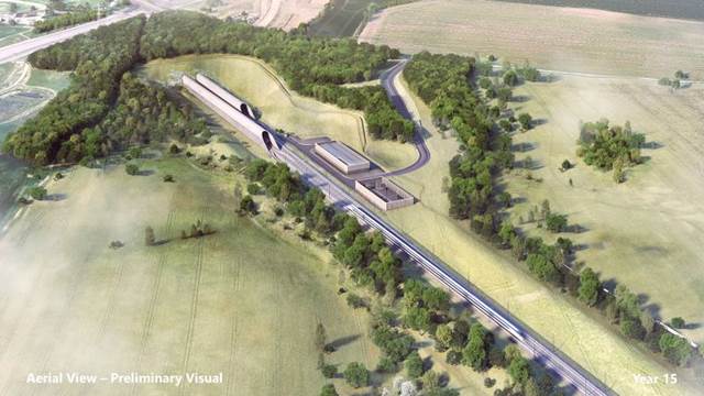
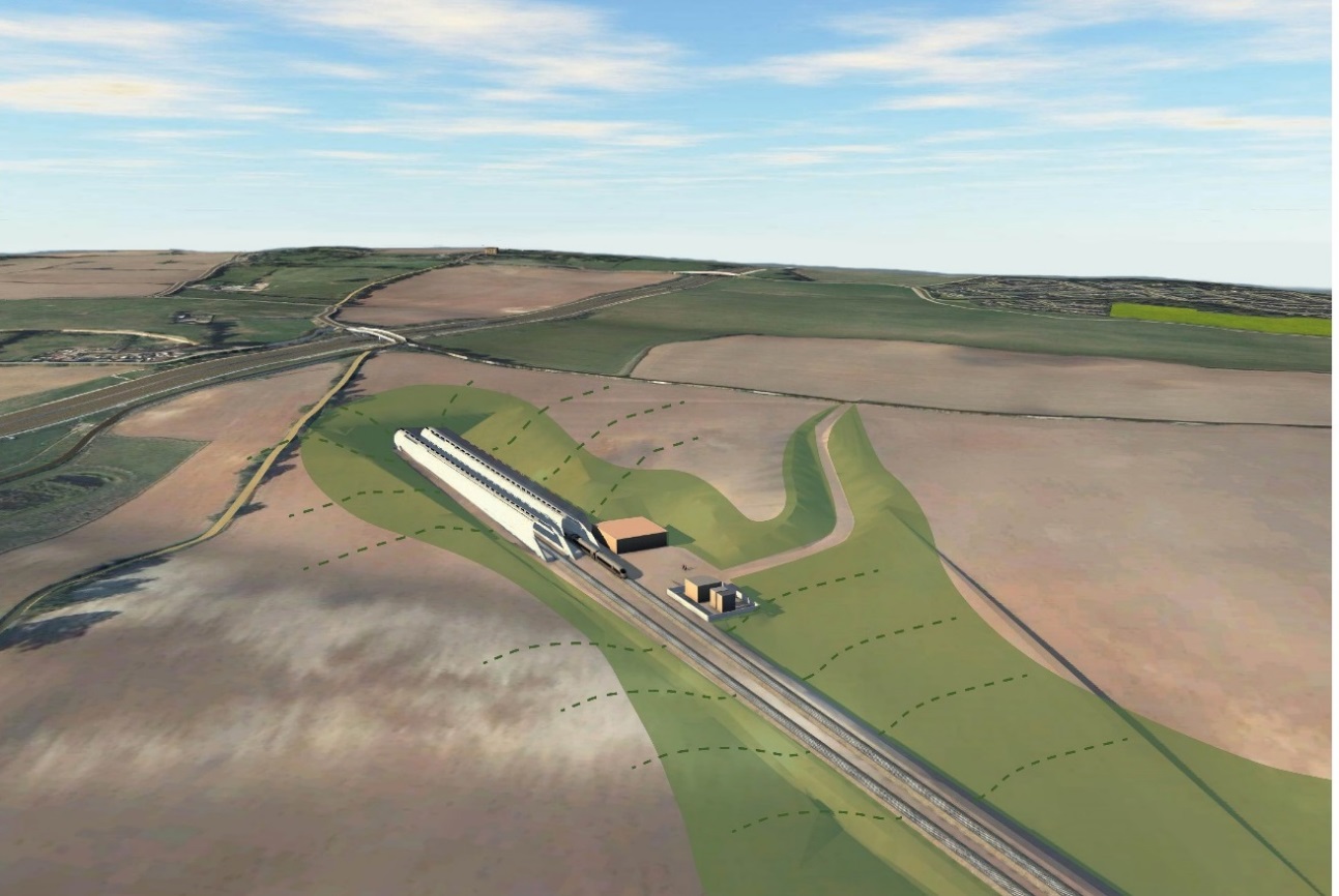
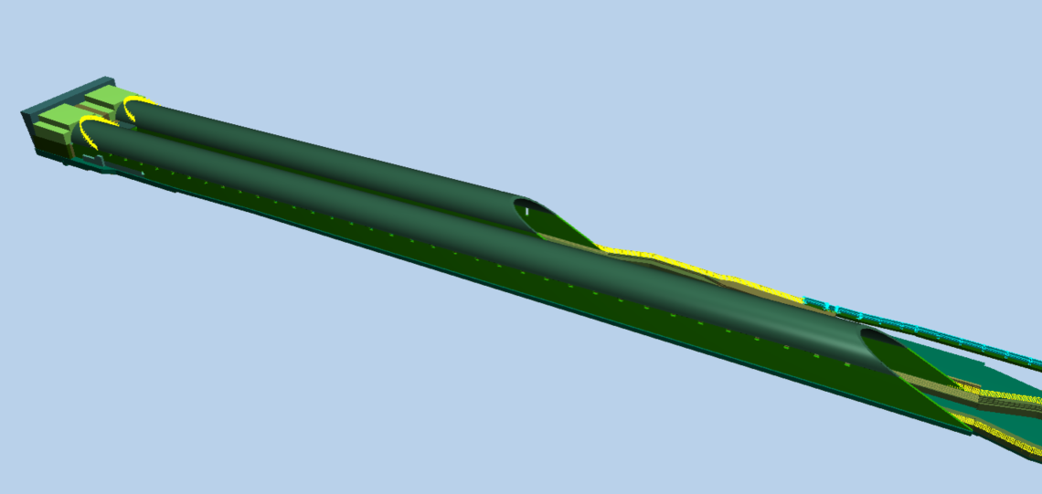
The process of developing this design is described in detail below, including consideration of the options for material and structural form and selection for the Stage 1 preliminary design, development and changes to the design as it evolved through Stage 1 and Stage 2 detailed design, and a summary of the main design features of the final design of the portal structures. Figure 1 shows the overall portal structure arrangement.
Stage 1 Design
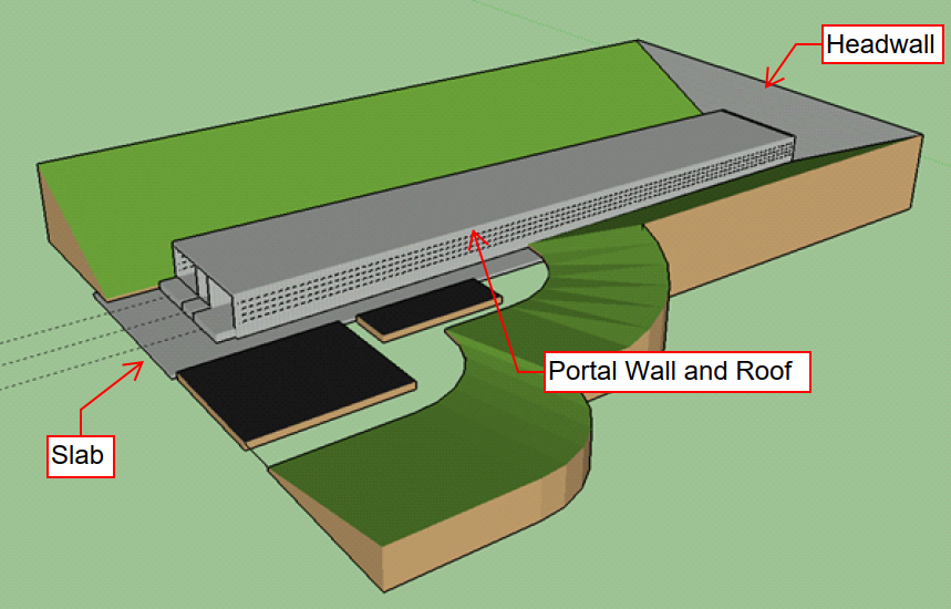
The design team inherited a preliminary design developed in order to achieve government backing through the hybrid Bill. The hybrid Bill design consisted of twin tapered cast insitu boxes 8.8m x 8.8m square at the tunnel interface. The walls and roof sections were 1m thick and supported on a temporary base slab of about 50m wide by 220m long, to be cast outside the portal position and to include a cradle for supporting the TBM during launch and facility for jacking during launch. See Figure 2 for an illustrative representation of the hybrid Bill Design and its basic components.
The stage one design focused on achieving an aerodynamic compliant structure while also complying with HS2 technical standards and constructability. However, it was clear early on in the design, that the requirement from the slab to facilitate the TBM launch was as vital as complying with any of the permanent works standards.
To ensure that the structure met the required aerodynamic design, set geometrical values were provided via the HS2 Spatial Arrangement Technical Standard [6]. The standard outlined the required length of the vented portal structure, which was 200m for the Chiltern Tunnel Portals. The standards also outlined the requirements for transition in free cross-sectional area from the tunnel end of the portal to the open end. For the Chiltern Tunnel Portals, the free cross-sectional area at the open / entrance end had to be 150% of that at the portal / tunnel interface.
Option selection and refinement
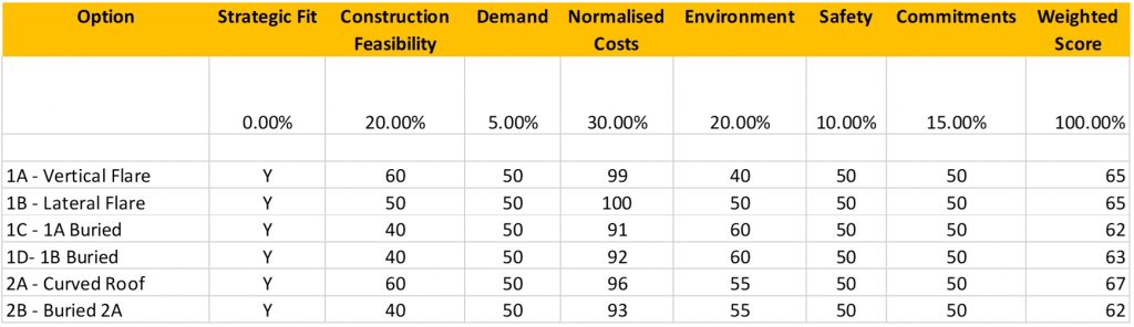
The design team produced a series of design options aimed at the sift criteria set by the Integrated Project Team (IPT). These included Strategic Fit, Construction Feasibility, Demand (journey time), Costs, Environment, Safety and Commitments.
There were two forms of construction considered; rectangular type structures with flat roofs, and arch like structures with semi-circular roofs. There were also two methods of achieving the 150% increase in free cross-sectional area considered; an increase in vertical height, and an increase in width. These were also combined with the option of being buried or exposed. Increasing both height and width simultaneously was not considered, nor an increase in width combined with an arch type structure, due to additional construction complications for no material benefit.
Three different options were considered for constructing the Chiltern Tunnel South Portals using; cast in situ, precast segments, or a combination of the two. The use of in-situ elements minimised joints and the risk of water penetration. The use of pre-cast elements would have required in-situ stitches with controlled construction stitch preparation to achieve a similar level of watertightness. It was later decided at detailed design stage to opt for casting in-situ for both constructability and durability reasons.
Achieving a 150% in free cross-sectional area
There were three methods considered to achieve an increase in free cross-sectional area from the portal / tunnel interface to the open end. The first was by increasing the height of the structure. The second was by increasing the width of the structure, and the third was by using a combination of the two. From a geometrical viewpoint, the design team discovered that increasing the height of the structure was the most efficient way of increasing the cross-sectional area compared with increasing the width. This was due to the fact that any increase in height increased the free cross-sectional area by 100%, however increasing the width also increased sections of the portal cross section which were not free (the walkways). Increasing the widths of the portals added additional variations to the plan, adding further complications to other disciplines that required space around the portal, such as drainage and landscaping. It was also noted that increasing the portals height was much easier to construct than increasing the portal width. It was also clear that using a combination of the two methods yielded no additional benefits over using a single method, but still inherited the issues with a structure that increased in width.
Buried or exposed
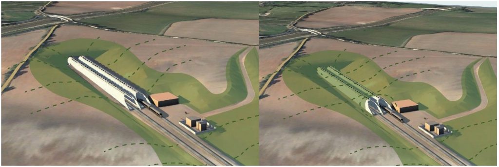
At this stage of the design, it was not known as to whether the structure was to be buried or exposed. Guidance documents depicted how the portal structure could be buried, with others showing an exposed structure. Two options were included for evaluation (see Figures 3 and 4). This was a significant driver in terms of design, as the portal walls were required to withstand backfill loading up to 1m below the perforations, increasing wall thickness, cost and programme.
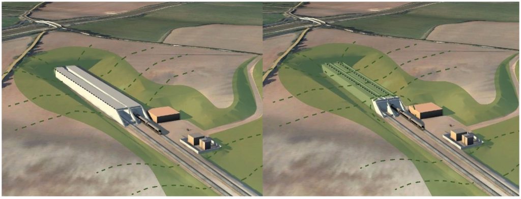
Arched or square roof
To help improve the interface with the tunnel eye, the design team proposed a series of options that contained a semi-circular roof (see Figures 3 and 4). This design allowed a more seamless integration with the tunnel and provided a more gradual change in free cross-sectional area (no square box transition onto circular tunnel). This design also improved the capacity of the structure when backfilled, as it acted like an arch in compression.
Three differing options were considered for the construction, using cast insitu, pre-cast or a combination of the two. At this stage, the design team wanted to keep as many construction options available.
The design team produced feasibility calculations for all the options considered. This meant that approximate sizing of elements could be produced, which helped during the SIFT process to identify the most suitable option. The design team identified key load cases that would determine geometries and were split into temporary and permanent considerations. One of these was the fatigue loading on the portal walls caused by the aerodynamic effects of the passing trains. At this early stage, it was difficult for the design team to identify exactly what load and partial factors were applicable to the tunnel portals, as the aerodynamic analysis was not finalised. The number of cyclical loads (>10 million) were also outside the guidance given in Eurocode 2 for steel reinforcement. The design team took a conservative approach, utilising a clause limiting steel stress to 70MPa, along with concrete compression fatigue checks. This approach gave a good basis for the radial reinforcement required within the portal walls and hood.
Every option shared a generic slab, the main function being as to facilitate the launch of the TBM. The integrated design team worked together closely to ensure that the geometrical requirements for the temporary works were met. Meetings were held on the principles of TBM launching and how to integrate temporary works requirements within the permanent works.
Due to the South Portal design programme being the first asset in the C1 contract, the TBM design was not at a sufficiently progressed stage to provide the required information, with estimates being provided from previous tunnelling jobs for loading and required geometry. As a result, the portal design team took a proactive approach to the design of the slab, ensuring it was geometrically flexible enough to accommodate changes, with enough spare capacity as to not require largening the element later and potentially impacting other disciplines.
The options were also reviewed by the other disciplines, identifying potential issues with drainage, architectural aspects, environmental (CO2/carbon footprint) and also accounted for input from other local stakeholders.
Based on the SIFT criteria, the options were evaluated (see Figure 5), with an exposed curved roof option that increased in height scoring the highest.
Integrated Alignment solution
As part of a wider value engineering study the design team proposed a simple alignment change for the area of the Chiltern Tunnel South Portal which had significant benefits in terms of the cost, construction programme as well as the carbon footprint of the project. The proposal kept the 4.5m track separation required on the Colne Valley Viaduct (to the east of the South Portal) as long as possible. This resulted in the whole site being tapered instead of the portal being located on two parallel tracks at 21m centres as per the hybrid Bill alignment. The principle driver of the alignment change was a reduction in the volume of cutting excavation required not only through the South Portal area but also the subsequent West Hyde Embankment and Tilehouse Lane Cutting. The above change in P-Way alignment also included a 100m relocation of the portal structure. This was to reduce significant risk of the tunnel adversely effecting a foundation of a gantry over the M25, while also moving the zone of influence away from the M25 and allowing for the installation of ground settlement/heave monitoring ahead of the TBM reaching the M25. It was estimated that the cut volume was reduced by over 50% with over 9,000tonnes of C02e being saved.
Some interpretation of design standards by the design team was required for the portal structure, which often fell somewhere between a tunnel and an open route asset. The design team made use of the standards for tunnels or bridges (although some specifically for portals). Where significant decisions were required on applicability of specific standards, the interpretation of the relevant standard was agreed with HS2.
At the end of the stage 1 design (see Figure 6), the portal slab was 2m deep at the cradle end, reducing down to 1.5m, then 1m, and consisted of C40/50 concrete with B32 reinforcement running longitudinally in the 2m deep section, dropping to B25 reinforcement for the 1.5m & 1m deep section, and B25 reinforcement running transversely throughout. The walls and roof were both 500mm in depth, also consisting of C40/50 concrete with B25 reinforcement running both longitudinally and transverse. The tympanum varied in thickness and consisted of a lower strength grade of C32/40 (unreinforced in the cutting face area) to make it easier for the TBM to cut through during the launch.
Stage 2 Design
In Stage 2 the design was developed in more detail to ensure the permanent structure could be constructed whilst meeting all the temporary works requirements. This was heavily centred around the tunnelling activities and ensuring the TBM could be successfully launched off the slab followed by tunnelling activities without any permanent damage to the slab. The TBM launch is a critical part of the HS2 Phase One programme therefore it was a key driver in the portal design to design a structure that would allow this to happen and integrate any temporary components into the permanent design.
Construction stages and associated challenges
Initial 20m section of slab
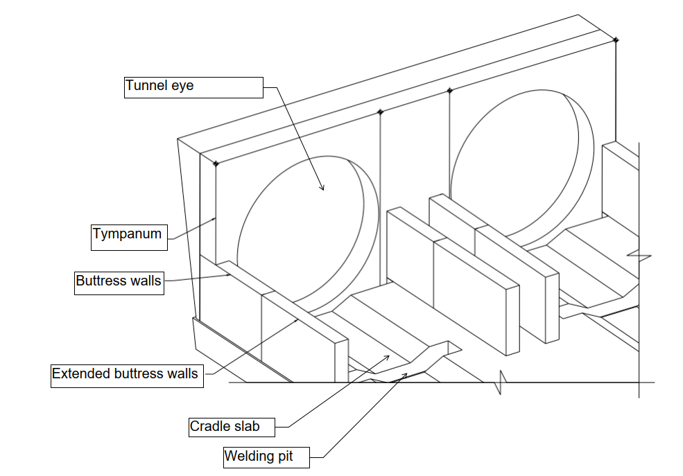
This section of the slab is situated adjacent to the tunnel eye and is subject to the most severe conditions during construction where it has to resist the extreme thrust forces produced by the TBM. The geometry of this section of slab was adjusted to suit the TBM requirements which includes the following (also see Figure 7):
- Cradle slab beneath both tunnel eyes extending circa 19m to allow the TBM to be correctly aligned and positioned prior to launch.
- Recess beneath the TBM sealing ring. This recess is located directly underneath the headwall where a steal ring is placed with the diameter of the tunnel in order to resist hoop stresses and grout pressures. For the steel ring to be placed a recess was required in the portal slab which, in turn, presented a capacity challenge as this is now a ‘weak’ point.
- Welding pit. A rectangular recess within the cradle slab to allow TBM assembly
These various geometry changes required flexible solutions and a thorough understanding of the temporary works to provide effective solutions that would not compromise the capacity of the portal slab.
Tympanum, Tympanum Wedge and buttress walls
After the initial slab pour the headwall is cast. The head wall chosen was a tympanum which consists of a partially reinforced concrete wall approximately 13m in height where the central section remains unreinforced to allow the TBM to cut through efficiently. The outer surrounding sections will be reinforced sufficiently to resist the over grout pressure that will? be exerted on the tympanum from the opposite side once the boring begins. In order to resist these forces and strengthen the tympanum wall, two buttress walls are provided either side of each tunnel eye extending along the slab. The buttress walls provide several functions at different stages in the construction:
- To support the tympanum during TBM boring (as mentioned above)
- Tunnel rings will extend out of the tunnel eye for approximately 12.5m. In order to quickly stabilise these rings and prevent any ovalisation, mass concrete will be poured where the two buttresses effectively act as permanent formwork for this.
- To act as part of the portal superstructure as portal walls. Couplers are provided in the top of the buttress walls and at the longitudinal end in order to have reinforcement continuity and therefore a more efficient structure.
The issue of continuity was a challenge between the tympanum structure and the portal hood in the permanent design condition. To solve this reinforcement bars were hooked onto the sealing ring in the portal hood as there was a steel lip protruding from the tympanum. This allowed an effective anchorage into the tympanum.
Shifting ways and thrust frame support
Sitting behind the initial section of portal slab approximately 17m from the tunnel eye are shifting ways. These consist of two rectangular concrete blocks adjacent to each tunnel line, 23m in length that have an internal sloped face to allow the TBM Back Up Gantries run along. The shifting ways will be subject to gantry loads throughout the launching of the TBM. They have also been aligned with the outside of the portal and had to be integrated into the portal walls. The thrust frame back legs are positioned diagonally on the thrust frame footing located on the shifting way. These required significant reinforcement to resist the thrust force of the TBM of over 6000kN.
The cross passage aligns with the first 4.5m of the shifting way therefore couplers are used to allow the bottom slab of the cross passage to be integrated into the shifting ways.
The shifting ways have been designed to be integrated into the permanent portal walls, and eventually the internal walkways. The requirement for complete crane access to the slab to facilitate construction of the TBM meant that no starter bars for structural continuity between the slab and portal walls were allowed. The solution was to detail coupler connections between the slab and walls, allowing for structural continuity without fouling the TBM or crane movements. This solution also eliminated the risk of impalement on site.
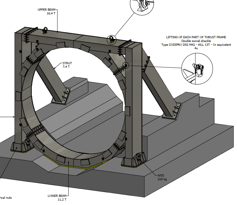
The thrust frame is an integral part of the TBM launch and consists of a diagonal frame with front vertical legs places on the slab and then diagonal legs resting on the shifting way thrust frame footings (see Figure 8). During the TBM launch this is used to brace against opposing forces which generates significant uplift in the front legs and compression in the diagonal back legs. The front legs are a critical design aspect for the slab and holding down bolts and anchor plates will be embedded into the slab to resist the tensile forces. Due to such large forces, the slab and shifting ways had to be designed with additional shear links. The link design kept utilisation low enough to ensure there was no permanent shear cracking to the slab.
Cross over slab
During the design the requirement for a crossover was instructed, and the only suitable location was outside the South Portal; not ideal due to the portal proximity and the large number of under track crossings (UTXs) in this region. A review of the risks associated with this change highlighted the need for an additional crossover slab (of circa 340m total length) to control vertical settlement and stiffness to strict HS2 requirements. The design of the slab-track system would also need to be compatible with the longitudinal thermal movements of the portal slab. It was not considered acceptable to allow the portal slab longitudinal thermal movements to cause movements to the sensitive crossover area, and hence a joint was proposed between the two to effectively isolate the crossover slab from the portal structure. The challenges faced on the cross over slab mainly consisted of providing a solution which would not impede a vast amount of services and utilities consisting of:
- UTX cables and troughs
- Drainage chambers
- UTX troughs within the walkways
Portal structure – shortening of the upline portal
The portal structure design was initially two equal length portals hoods for the full length of the portal slab with a similar vent arrangement on both ends. After further aerodynamic analysis and refinement it was determined that the downline portal had to increase from 200m to 220m, and upline portal could be reduced from 200m to 135m as the aerodynamic pressures for a train entering the tunnel is substantially different to one exiting. This allowed significant saving in the portal hood materials and construction time. During this stage, the design team challenged the initial instructed vent arrangement, which insisted the vent heights varied along the length of the portal structure. This meant that every single vent had to be a different height, adding construction and detailing issues. By working closely with the HS2 aerodynamic design team, the portal design team proposed an arrangement that grouped the vent heights, provided the same vent cross sectional area, but was much easier to design and construct for the contractor.
Permanent structure design
The permanent structure (Figure 9) was designed in accordance with the Eurocodes and the HS2 standards.
The design of the portal was viewed as a concrete underline structure however the portal hood is obviously not supporting the track and only supporting its own self-weight, aerodynamic pressures and a backfilled section near the tunnel end.
Aerodynamic loading
The aerodynamic load was provided by a specialist analysis undertaken by HS2 where they provided design data for the loading that the pressure head would create on the portal hood (generally up to approximately +/-5 kPa depending on position along a portal). This force would be applied to the inside of the portal hood creating both positive and negative pressures as the high-speed train passes through. This load was considered to be cyclic (number of cycles will equal the number of trains passing through in the 120-year design life of the structure) therefore it was critical to check the fatigue resistance of the portal hood.
Thermal loading
As the portal had no movement joints in order to provide a 120-year design life the thermal effects on the structure were critical to the design, the portal was designed to resist any thermal expansion and contraction within the serviceability limit state (SLS) and ultimate limit state (ULS) stipulated in the Eurocode and additional allowance for climate change. This loading governed the requirement of longitudinal reinforcement required in the slab through to the portal hood as the hood or slab would be subject to tensile forces depending on the expansion or contraction of the portal. The movement due to thermal actions was calculated and limited in order to not impact the design.
As the thermal loads were critical in the 235m long structure cracked section properties were utilised in an iterative analysis to develop an efficient design. The quasi-permanent SLS cases proved critical and crack widths had to be limited in to 0.30mm in order not to impair the durability of the portal. A detailed analysis was undertaken to satisfy that there was a sufficient amount of steel reinforcement to control the expansion and contraction throughout the portal hood and at specific interfaces such as the interface between the overlay and the portal hood where there was a change in geometrical properties.
Seismic
As per the HS2 standards the portal structure was subject to a seismic design. This was to ensure that a project wide requirement for the structures to ensure resilience for the 120-year design life and to ensure no repairs should be undertaken on the structure in the event of a design earthquake situation. The portal will act within the elastic rage during an earthquake situation and a range of 2D and 3D models were used to analyse the portal in its critical areas:
- 2D model for the open end of the portal (no backfill)
- 2D model for portal at the tunnel end where there is backfill and retained earth pressures
- 3D model of the portal to check global transverse stresses and deflections.
For the design the limited ductility approach, introduced for the first time in the Eurocode 8, has the main advantage of simple analysis and detailing with no confinement required. This allows materials exhibit a small degree of the post-elastic behaviour using allowable strains compatible with unconfined concrete (approximately 3.5‰ for concrete and 10‰ for steel).
Due to the very low ground acceleration expected at Chiltern Tunnel South Portal, it was considered appropriate to pursue the limited ductility approach to avoid the requirement of complex and costly detailing of plastic hinges. The limited ductility approach is warranted on the basis of robustness and structural choice. The design using the limited ductility approach, introduced for the first time in the Eurocode 8, has the main advantage of simple analysis and detailing with no confinement required. This allows materials exhibit a small degree of the post-elastic behaviour using allowable strains compatible with unconfined concrete (approximately 3.5‰ for concrete and 10‰ for steel).
Fire design
The portal structure was required to be designed for the EUREKA fire curve, similar to the tunnel. The HS2 requirements for this event were that i) the portal would not collapse under working loads during or after such a fire, ii) repairs for fire damage would not be excessively difficult. The approach used for the portal hoods was to undertake a non-linear analysis of the portal hood including loss of thickness due to spalling (limited to 75mm by HS2 standards) and loss of concrete strength/stiffness due to thermal gradient through the portal hood thickness. The assumptions and requirements for this design were provided in a fire test specification for fire test panels, in particular the spalling depth, coexisting compressive stress in the portal hood during the fire, and temperature within the test panel section thickness (e.g. reinforcement temperature which was also limited by HS2 standards).
Similar to the tunnel, the portal hood components incorporated polypropylene fibres within the concrete specification to mitigate the risk and severity of spalling. To ensure high confidence in the portal hood concrete specification prior to the fire tests, a review of previous similar tests on other projects such as Crossrail5 was undertaken.
Durability
The portal structure was designed for 120-year maintenance free design life. This was achieved by enhancing the concrete specification via an increased cover value to reinforcement (typically an increase of 15mm for in-situ concrete), avoidance of joints, and providing two layers of water management protection in buried portal zones, achieved by limiting crack width to 0.3mm in combination of waterproofing with additional protective layers.
Conclusions and recommendations
In order to avoid construction of a temporary slab which would then have to be demolished prior to construction of the permanent works an integrated solution has been produced. The significant programme benefit this gives is that the temporary launch slab could not have been demolished during tunnel construction as it would have interrupted the supply of tunnel segments to the boring machine. The removal of the need to do any demolition therefore removes a section of works directly from the critical path of the programme
The design team purposely utilised design capacity required for the permanent design scenario and utilised it for the temporary design scenario, and vice-versa. An example of this includes utilising surplus capacity in longitudinal steel members during temporary design for more economical shear design. By taking this design approach, the structure was lean and economical for both temporary and permanent design scenarios.
One potential method of designing more efficient high-speed porous portals with few or no joints, would be to consider the use of concrete materials with lower coefficient of thermal expansion (CTE) to minimise thermal forces. One example would be lightweight concrete, which has a lower CTE and elastic modulus than that of normal concrete. These material parameters would typically halve the thermal expansion/contraction forces within the restrained structure. The requirement to launch and recover TBM’s naturally presents large overburden loads from soil backfills. Lightweight concrete would also significantly reduce the expected settlements due to the reduction in self-weight. However, as this material has a shorter track record than normal reinforced concrete, further work would also be required to more reliably confirm the 120-year durability and minimise the risk of maintenance, and also the effects of tens of millions of fatigue cycles from the aerodynamic pressures caused by high-speed trains.
References
[1] Atkins, ‘High Speed Rail in the Chilterns Part 1: General Long Tunnel Requirements’, 2015.
[2] Atkins, ‘High Speed Rail in the Chilterns Part 2: Chiltern Long Tunnel Proposal’, 2015.
[3] Johnson, T., ‘Measurements of the Effect on Pressures of a Porous Portal Tunnel Entrance Using a Moving Model Rig’, Birmingham University, 1999.
[4] Derkowski, P., Clark, S., and Sturt, R., ‘Aerodynamic Effects of High Speed Trains on Passengers, Track Workers, and Other People’, AREMA, 2014.
[5] King, M. ‘Protection Against Fire For The UK Crossrail Tunnel Structures’, Crossrail Project, Infrastructure Design and Construction, Volume 5, ICE Publishing, 2018.
[6] HS2 Technical Standard – Spatial Arrangements
Peer review
- Colin Rawlings, Lead Tunnel EngineerHS2 Ltd