HS2 Interchange Station – Innovative Roof Design: An exemplary project on Integrated Design Team collaboration and the use of advanced Digital Workflows
The design of the roof at Interchange station embodies the HS2 Design Vision. It is both a conceptual response to its site’s rural context and a demonstration of how integrated design can achieve a solution that is visually elegant, cost effective, simple and safe to construct, that minimises both operational and embodied carbon and is safe to maintain.
This paper examines how design technologies and workflows, when married together, can create a seamless workflow that has allowed both the architectural concept and technical requirements to achieve the HS2 Design Vision and a BREEAM Outstanding rating. HS2’s carbon reduction ambitions are set very high. The integrated design team actively implemented passive strategies (i.e. solar control and natural ventilation) to avoid the need of mechanical ventilation systems in the main concourse whilst also limiting the moisture content in the main glued laminated timber portal frames to achieve 120 years lifespan.It
The paper will articulate how HS2’s carbon ambitions can be achieved by holistic design and an integrated team. Passive strategies (i.e. solar control and natural ventilation) were carefully implemented to avoid the need of mechanical ventilation systems in the main concourse whilst also limiting the moisture content in the main glued laminated timber portal frames to achieve 120 years lifespan.
It will cover how the Arup The design team used innovative design software (Speckle, Rhino, Grasshopper, Revit) to create an integrated and seamless flow of information and ideas unifying the architecture (massing / design concept), the structure (primary portal frames) and the facade (geometry rationalization and secondary structure). This allowed the team to work parametrically to rationalise and optimise the roof form to achieve both cost and carbon efficiencies. It will show how the The use of lightweight glued laminated timber for the structure of the station roof allowed simplification of other structural elements and how with good design other technical requirements can be either removed or simplified.
The paper will also show how the ‘leaf’ architectural concept facilitated Design for Manufacturing and Assembly (DfMA) principals, where the roof was formed from repeatable forms, broken down into standard components that can be economically manufactured, pre-assembled and safely/efficiently constructed onsite.
- Written by
-
Fernando Ruiz Barberan

-
José Carlos González (SCS/Arup)

- Resource type
- Resource type: Technical Paper
- Intended audience
- Contractors
- Tags
- BREEAM posts
- collaboration posts
- design posts
- DfMA posts
- Digital workflows posts
- INterchange Station posts
- natural ventilation posts
- roof posts
- software posts
- solar control posts
- station posts
Introduction
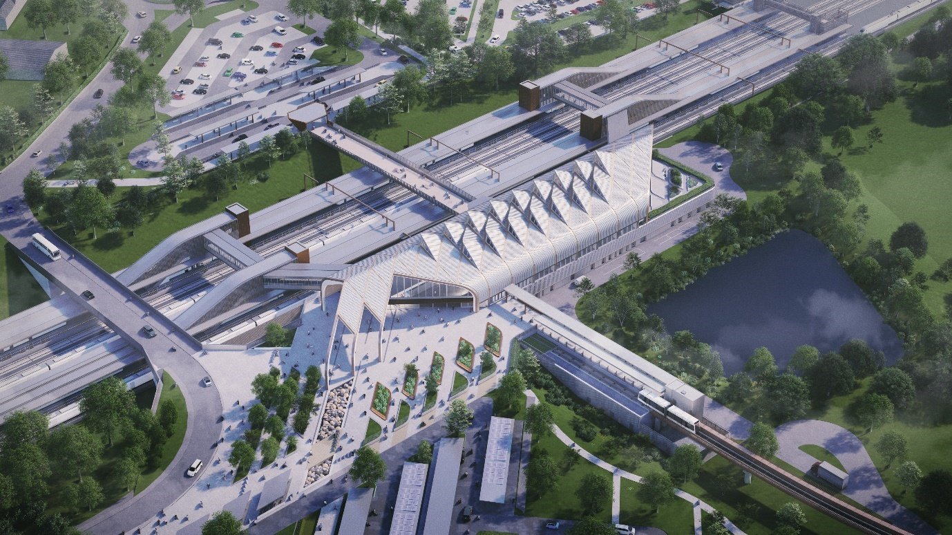
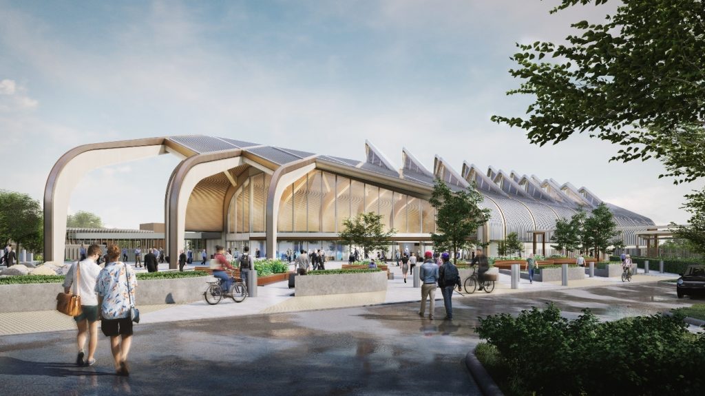
HS2 Interchange Station design (Figure 1) was assessed as BREEAM Outstanding[1] in the summer of 2020, making it the first rail station in the world to achieve this rating and making it potentially one of the most sustainable new building to be built in the near future. The main concourse roof was a significant contributor in helping to achieve this and embodies the HS2 Design Vision.
This paper shows the benefit of how design technologies and workflows, when married together, can create a seamless workflow that has allowed both the architectural concept and technical requirements to achieve the HS2 Design Vision and a BREEAM Outstanding rating. HS2’s carbon reduction ambitions are set very high. The integrated design team actively implemented passive strategies (i.e. solar control and natural ventilation) to avoid the need of mechanical ventilation systems in the main concourse whilst also limiting the moisture content in the main glued laminated timber portal frames to achieve 120 years lifespan.
The Arup design team used innovative design software (Speckle, Rhino, Grasshopper, Revit) to create a seamless flow of information and ideas unifying the architecture (massing / design concept), the structure (primary portal frames) and the facade (geometry rationalization and secondary structure). The design team developed the ‘leaf’ architectural concept which facilitated Design for Manufacture Assembly (DfMA) principals, where the roof was formed from repeatable forms, broken down into standard components that can be economically manufactured, pre-assembled and safely/efficiently constructed onsite.
The Interchange station is part of the HS2 network, serving the West Midlands, Birmingham Airport and the NEC conference centre, and with seamless links to the UK motorway system. The station sits within a green triangle formed by the M42, A45 and A452 to the east of the NEC, known as ‘The Triangle’ site. The station is connected to NEC, Birmingham International Railway Station and Birmingham Airport by an automated people mover.
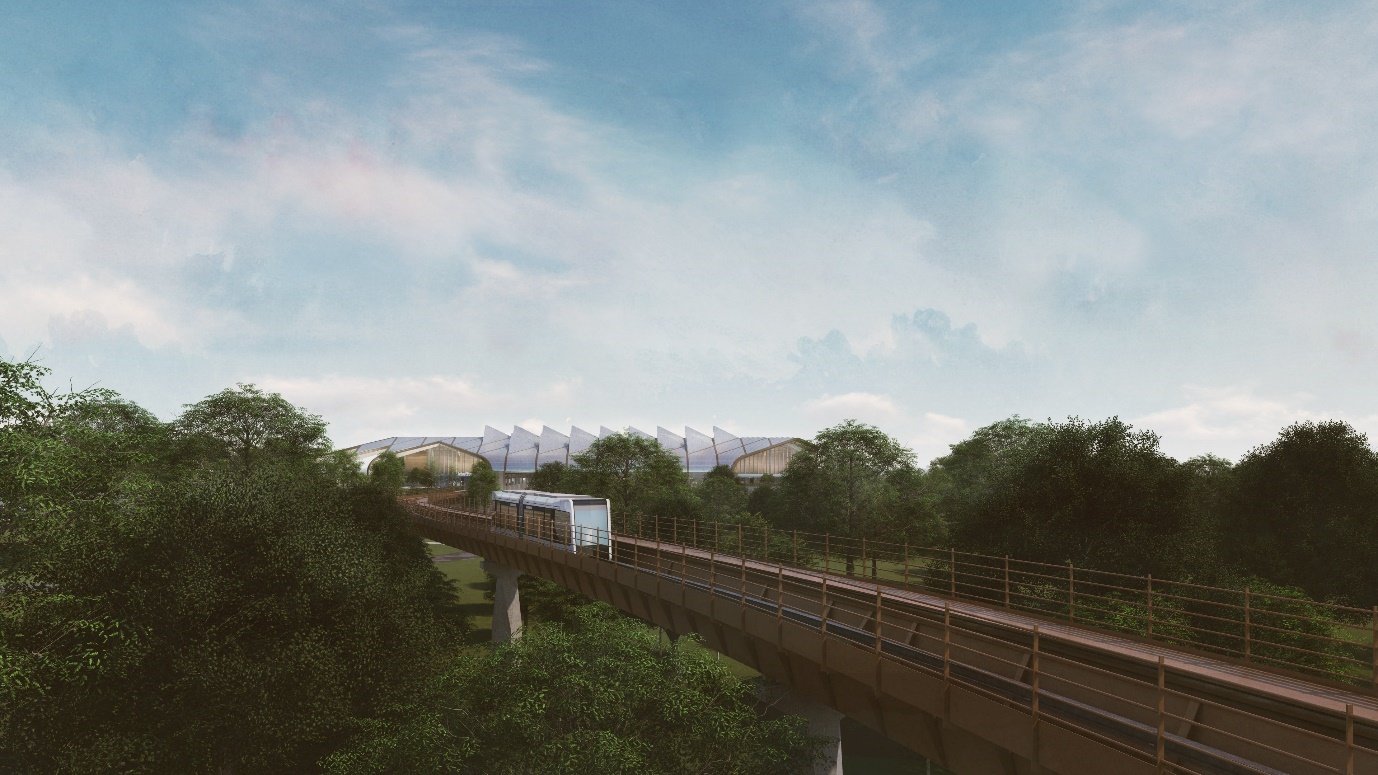
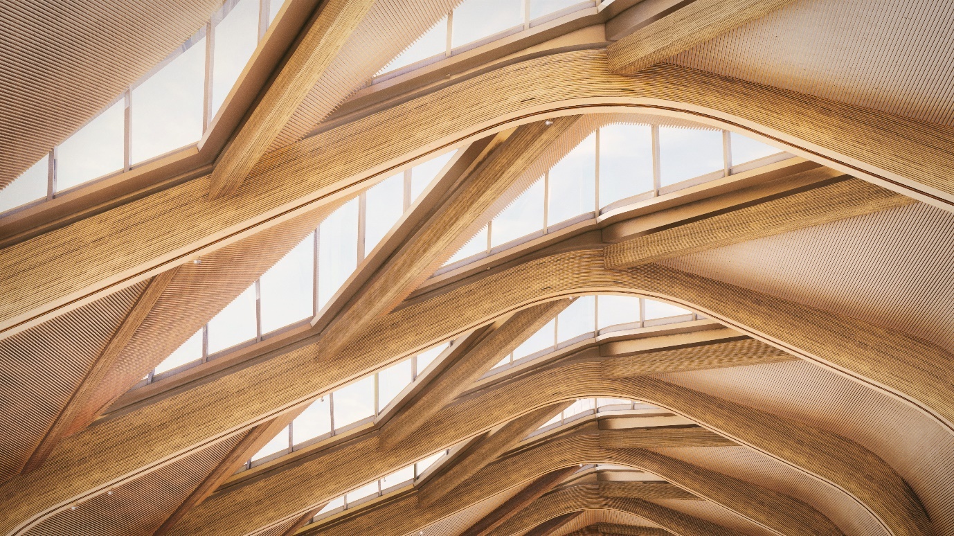
The architecture of the station reflects its role as a gateway to the West Midlands with the silhouette of the concourse roof (Figure 3) announcing its presence in the landscape. The design vision for the station is derived from its landscape setting and ambition to work in sympathy with nature. The roof has been designed to create a sense of place for the station, the rail network, the site, its surroundings and neighbour communities.
The roof (Figure 2) is conceived as a series of interlocking curved diamond-shaped leaves, which like their natural inspiration are designed to work with the environment. Their form directs rainwater to a diagrid of gutters which in turn lead the water towards a harvesting tank for reuse as greywater. The gutters channels also provide a safe route for maintenance and cleaning of the lights. The overall roof curves down at the eaves to enclose the main public concourse of the station and reducing the solar gain from low level sun from the west. The lower section of the Eastern façade is glazed to given passengers a panoramic view of trees of Hollywell Valley and the landscape beyond. The leaves are upturned towards the north to allow light into the station concourse while minimising solar gain inside the concourse.
The roof assembly sits on internal curved glued laminated timber beams at nine metre centres running orthogonally to the main concourse. The glued laminated timber beams curve down to sit on shaped steel 3.5-metre-high columns along the western elevation and on the retail and service block along the eastern elevation. Secondary beams run diagonally between the primary structure to carry the edge of the roof leaves. The gutters above sit on both the primary and secondary structures.
The southern gable is angled towards the views over Hollywell Brook valley and leads to a landscaped terrace, and the roof is extended by four and a half metres at the south gable of the concourse providing solar screening. At the north, the gable is angled towards the central public plaza set to the north-west. This end connects the station building with areas available for future expansion development in case of being required by the railway infrastructure. The roof is then extended, forming a portico over the plaza, clearly defining the entrance into the station and creating a sense of place. The extended roof sits on curved steel beams that mirror the form of the glued laminated timber beams inside.
The roof is finished internally with timber slats with acoustic backing which complement the visual warmth of the glued laminated timber beams which together create a visual connection to the surrounding landscape contributing to the well-being of both HS2 passengers and staff. The roof leaves give a dynamic appearance providing a sense of directionality. On entering, the roof appears as a consistent undulating plane, whereas for arriving passengers, the roof plane is punctuated by the north lights giving views up to the sky.
The use of timber glued laminated timber has been inspired by both the historical use of timber in railway buildings as well as the benefits of carbon reduction that the use of timber allows. Notable precedents are Brunel’s original terminus at Temple Meads which has a wooden cantilevered roof and was completed in 1841. The original roof of Kings Cross by Lewis Cubitt, when opened in 1852, was supported by laminated timber arches. These were replaced by the current wrought iron structure from 1867. Further afield in Europe the roof of Stockholm Station, opened in 1925 and still in place today, is an early example of glued laminated timber structures.
Design process
The approach for the development of a holistic solution for the station roof reflects the HS2 Design Vision[2] which relates to three core principle: “people, place and time”. In addition, the structural design of stations aims to reflect the rich history of innovation that is an intrinsic quality of the design of great railway stations worldwide.
The design ethos is therefore to express the structural elements, for the structure to convey how the roof is formed, how each element responds to the forces they carry and reflect the best of technological and industrial capabilities available. The structural form is therefore a strong element of the architectural concept, heavily influencing the passenger experience.
Through a collaborative and iterative approach to design, the performance requirements of the roof have given form to architectural aspirations for the project. The design has been developed to respond to the following themes:
- Robust and adaptable systems
- Safe to construct: DfMA and Design for Disassembly (DfD)
- Elegant, exposed structural forms
- Security
- Passive design principles
- Innovative Workflows and Digital Tools
1. Robust and adaptable systems
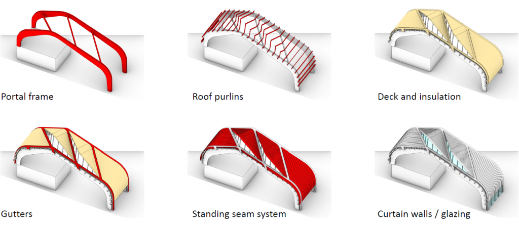
The roof consists of a repeatable 30m x 9m module containing a logical hierarchy of elements, which when combined form a holistic system allowing for the most efficient flow of forces and creating a form that closely follows the architectural intent.
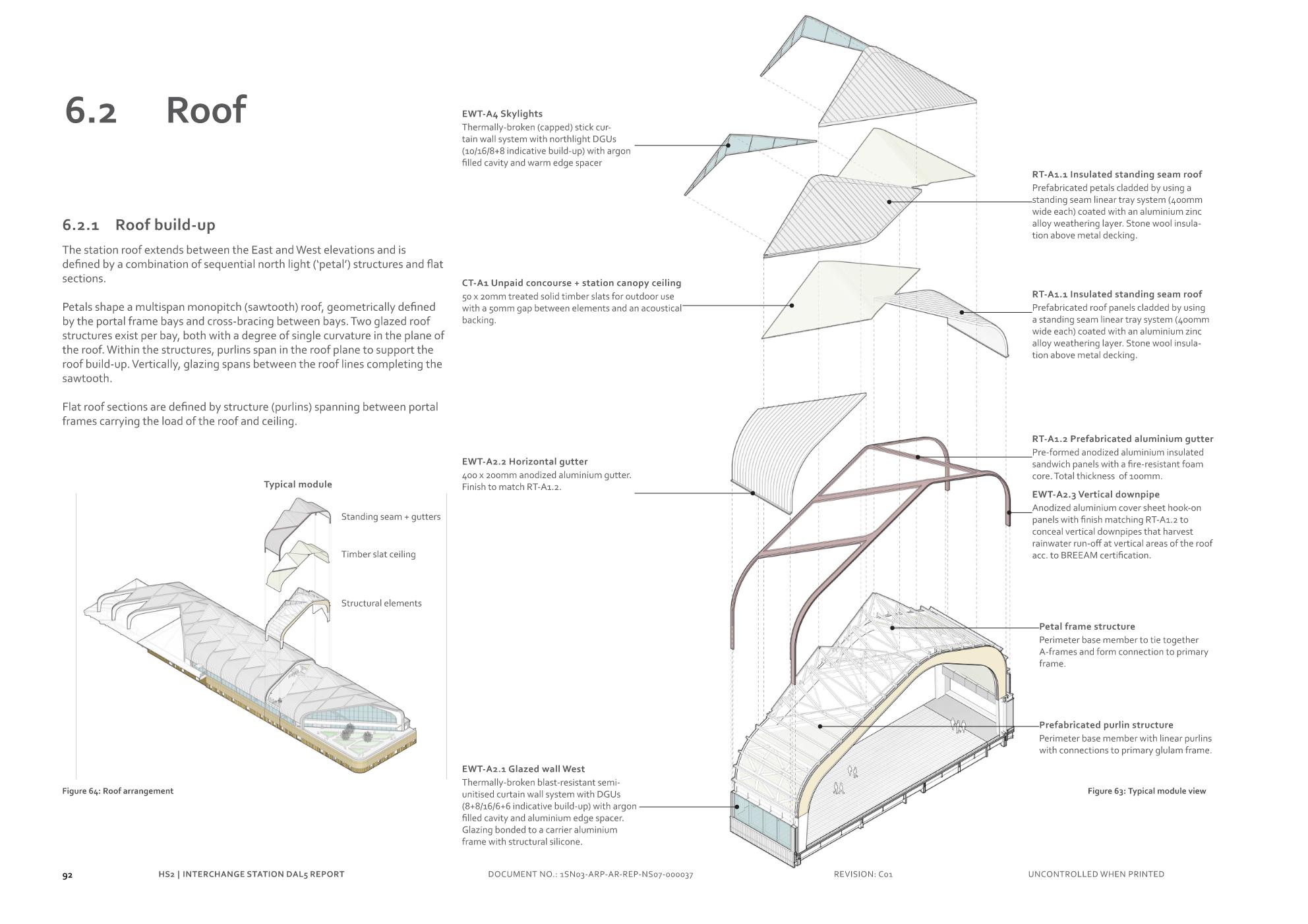
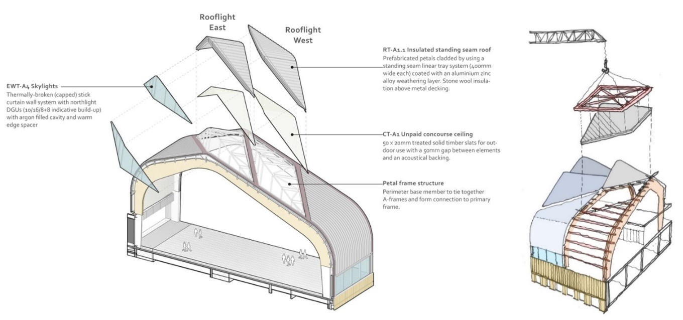
A layer of secondary structure, namely the petals and purlins, is required to complete the roof geometry and support the cladding, rooflight glazing and walkable gutters. Independent hot rolled steel frames form the petal structures consisting of vertical mullions and inclined purlins connected at their base via a continuous base rail. They are connected to the glued laminated timber structure via a series of steel stub connectors at regular centres which maintains a minimum 100mm ventilation gap above the glued laminated timber members. The petal structures are envisaged as discrete modules which can be prefabricated adjacent to the main roof on the ground including the cladding build-up and lifted into place to increase quality, reduce programme and most importantly improve construction safety.
The petals shape is a multi-span monopitch (sawtooth) roof, that is geometrically defined by the portal frame bays and the cross-bracing between the bays. Two glazed roof structures exist per bay, both with a degree of single curvature in the plane of the roof. Within the structures, purlins span in the roof plane to support the roof build-up. Vertically, the glazing spans between the roof lines, completing the sawtooth.
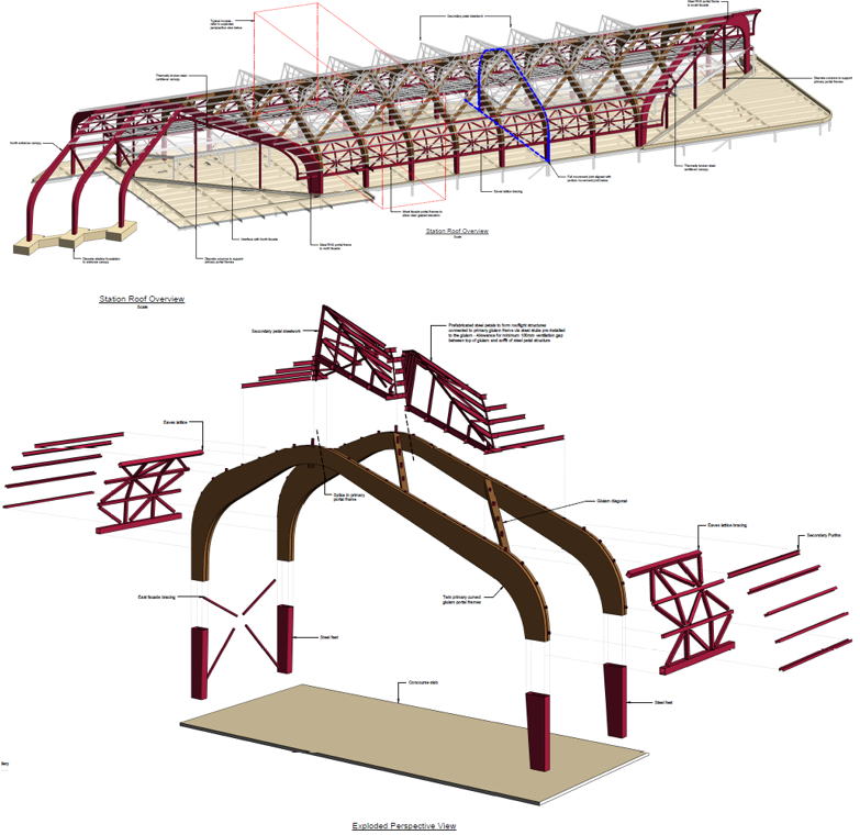
The main roof elements are categorised as follows (See Figure 4 below, Figure 17 and 18):
- Primary glued laminated timber portal frames (with steel feet)
- Diagonal glued laminated timber trimmers
- Steel lattice eaves bracing
- East Façade steel cross bracing
- Prefabricated roof “petals” (large diamond shaped roofing panels between gutters)
2. Safe to construct (DfMA, DfD)
Safety is the first design consideration, in all circumstances. In addition to the refinement of the architectural forms to mould them into efficiently performing structures, the design has been developed with Design for Manufacture and Assembly (DfMA) at the heart. This was made possible by the early engagement with Construction Planning specialists, embedded with the design team, who consulted on the design of elements and created the construction programme and methodology to assure that the design can be built safely, economically and within the programme.
The overall philosophy adopted throughout the design is to maximise offsite fabrication and minimise on-site operations, therefore reducing exposure to hazards and safety risks, improving quality and consistency of the delivered product and reducing the time for on-site construction. The aim is to produce a scheme primarily by a process of assembly, rather than construction. To this end, where possible, the structural work above foundation level should involve pre-casting and pre-fabrication of components offsite, which are delivered to site as required for installation. Initial component fabrication can be in a controlled factory environment, where the risk to personnel is minimal compared with site construction.
This has led to modular, repeatable forms throughout, broken down into standard components which can be economically manufactured, preassembled and safely and efficiently constructed on site. This approach supports Design for Deconstruction (DfD) as the result considers the whole-life of the structure and its materials, supporting HS2 and the design teams circular economy commitments.
3. Elegant structural form
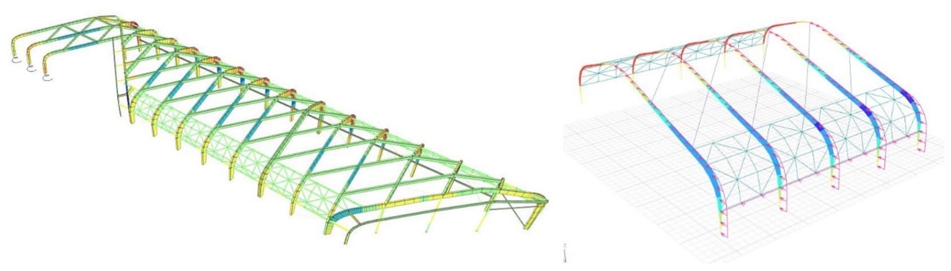
To achieve an innovative design and sustainable outcome, a “total design” approach was followed where architecture and engineering get integrated from the very beginning of the project. To achieve an innovative design and sustainable outcome, an engineered approach is sometimes required to stretch the possibilities of the design outside the “comfort zone” of design codes. The structural and mechanical engineers informed the design for the glued laminated timber roof structure (Figure 5) through different advanced simulations that contributed to a better distribution of loads, optimization of materials and internal moisture control.
A key feature of the roof is the use of glued laminated timber for the primary concourse roof structure (Figure 6). Glued Laminated Timber is a type of structural engineered wood product constituted by layers of dimensional lumber bonded together with durable, moisture-resistant structural adhesives. It has been chosen for its high strength to weight ratio, sustainability credentials, inherent durability, suitability for Design for Manufacture and Assembly (DfMA). The use of timber in the Interchange station roof uses 400 tonnes less embodied carbon than a fully steel alternative.
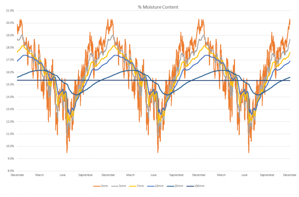
Timber is a hydroscopic material, meaning its moisture content will vary in response to the surrounding environmental conditions. The moisture content of timber has direct implications on its structural and durability performance and, hence, understanding the in-service conditions is an important aspect of the design process. The design team collaborated with timber experts and building physicists to conduct a dynamic assessment into the timber moisture content when exposed to the forecast environmental conditions.
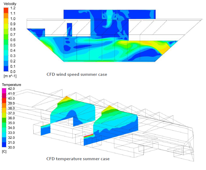
It was therefore necessary to demonstrate that the internal conditions did not result in a moisture content that could compromise on the 120-year durability requirement. Since the concourse relies on passive strategies (natural ventilation, roof insulation, energy optimization, sustainable materials, natural lighting, glare control or rainwater harvesting) driven by the Sustainability ambitions[3], these internal conditions were uncontrolled by means of mechanical systems. As a result, the variation range on moisture content fell outside the values given by the Eurocode. To overcome the issues, the Advanced Digital Engineering team carried out a Computer Fluid Dynamics (CFD) analysis for an accurate understanding of the humidity and temperature stratification considering the passive strategies such as natural ventilation. Due to the highly dynamic nature of the environmental conditions and absorption rates, a specialist software programme called WUFI (Wärme Und Feuchte Instationär, in German) was used by the Facades team to determine the moisture content of a timber member when exposed to the forecast conditions (See figure 7). The software provided a 1-dimensional simulation (i.e. timber section depth) to capture the temporal changes in Relative Humidity and Temperature. This, together with specialist input from the Materials team were key to demonstrate compliance with the durability requirements.
The predicted relative humidity and temperature of the concourse were determined using a forecast of future environmental conditions, taking climate change into consideration. The CFD analysis was showing the stratification of the internal conditions of the air. This was also key to fine tune the passive strategies and validate a design that did not rely on mechanical systems to provide comfort conditions for users, contributing thus to the reduction of the operational carbon footprint along with other strategies such as maximising daylight, rainwater harvesting or material selection. And becoming, this way, the first railway station in the world to achieve the top sustainability certification.
4. Security
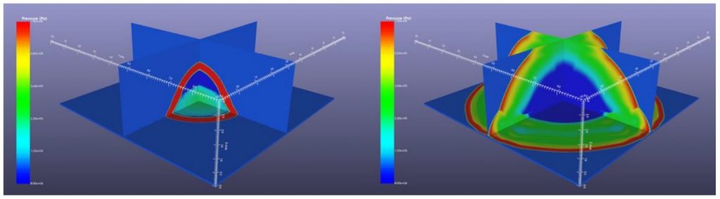
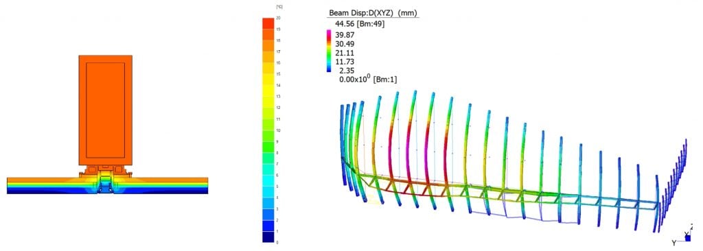
Given the stations strategic importance, it was necessary to engineer the solution to meet the resilience requirements in a blast event, driven by the Security team in collaboration with HS2 subject matter experts. The structure has been designed to allow for a suitable level of robustness, developed in close collaboration with the Arup Security team, the design basis threats have been determined through a Threat and Vulnerability Risk Assessment in relation with HS2 Operational Safety requirements[4] and the structural systems designed accordingly.
Blast roof simulations (Figure 8) have been carried out to verify the design compliance with the specific security requirements, from this process key principles were adopted in the roof design.
5. Passive design
Optimising the building form and orientation with respect to the climate is important to create comfortable and environmentally welcoming spaces that give a sense of warmth, freshness and light. The performance of the building fabric is important to reduce heat loss in winter via conduction through the walls and glass and the infiltration of outdoor air through small gaps. In summer the performance of the building fabric is important to prevent overheating. Fabric U-values and air tightness were based on the values in the Building Regulations Part L [5] as a minimum requirement and these were improved upon where it is found that there was a significant advantage in doing so.
The main axis of the station runs predominantly north/south, parallel to the track. Preliminary thermal model suncast simulations were conducted during concept design, which indicated that there could be a high amount of direct sunlight into the concourse area in the morning on the east facing façade and in the late afternoon on the west facing façade. In response, façade engineering studies were carried out to optimise the amount of glazing and façade design on the western façade to reduce the solar gain and direct sunlight into the concourse area and optimise the daylight into the space using north-facing rooflights.
To decrease the effect of cold external air entering the concourse during winter, reducing the likelihood of condensation and discomfort, a preliminary study has been performed using the thermal model to simulate the impacts of various sizes of air curtains on the entrance doors in an effort to maintain an average internal temperature of 3°C. The size of air curtains was estimated to be 180kW on the north and east entrance doors.
The openings of concourse doors have been modelled to follow the occupancy profile of the unpaid concourse. It was assumed in the model that the air curtains have a 50% climate separation efficiency, whereby half the heat supplied by the air curtains are lost externally and the other half is provided to the concourse. Similarly, it is assumed that the effect of the air curtains on infiltration through the doors while they are open will be reduced by 50%.
A CFD analysis (Figure 9) was conducted to assess Summer Overheating which confirmed that natural ventilation within the station concourse is sufficient to create the required internal conditions. Passive design alleviating the need, and expense of mechanical systems.
The building envelope key performance parameters were achieved due to the integrated collaboration across disciplines and is a great example of the orchestration carried out by the Design Team. This was crucial for the outcome of the project as many of these parameters had competing interests (see Figure 10, structural silicone glazing (SGG) thermal performance aiming for transparency and steel mullions sizing in front of roof portal frame). For instance, to provide comfort conditions to users it was important to provide openings at low level whilst from a security perspective this was the most challenging area due to the proximity of blast threats. Furthermore, comfort conditions were not necessarily aligned with the need to limit moisture content in the timber structure.
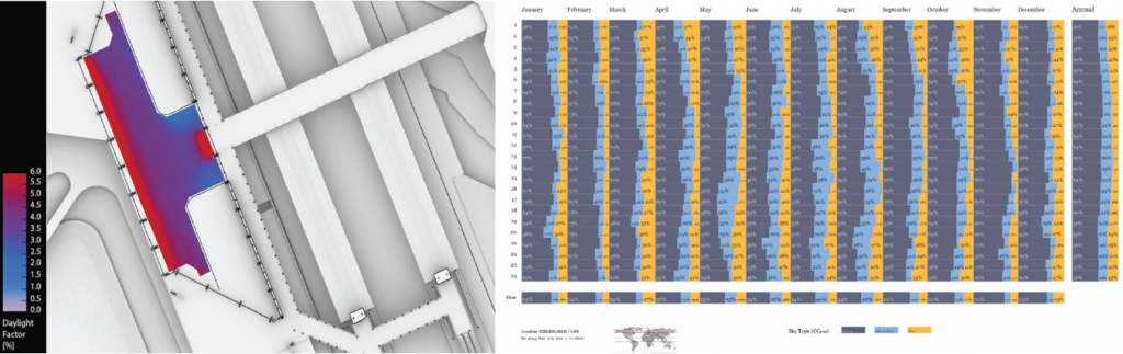
To develop the roof design, the design team needed to find the optimal balance between providing daylight and managing solar gain. A digital workflow was established to enable design team collaboration and the development of an optimum roof geometry.
Finding the right balance is required to create a more environmentally sustainable station. The approach the design team followed was to create a passive design to reduce the energy demand in the first instance and use smart systems to make more efficient use of the energy consumed thereafter. Accordingly, the roof design has been developed to exploit natural daylighting (Figure 11) and will use daylighting sensors to reduce electrical loads automatically based on occupancy and available natural lighting. There are two main sources of daylight for the main concourse: the façades and rooflights. The station diagonal roof structure allows the rooflights to face north, this allows diffuse daylight from the sky vault whilst avoiding the ingress of direct sunlight. As a result, less shading is required to control glare and solar heat gains. The proposed façade glazing at the north and south ends of the station, and the glazing along the full length of the west façade provide important views in and out of the station concourse, and help create a bright, inviting space, as well as supporting meeting target daylight levels in the unpaid concourse. In addition, the dynamism and drama of admitting direct sunlight into the station in a controlled way is a key component of the daylight design strategy
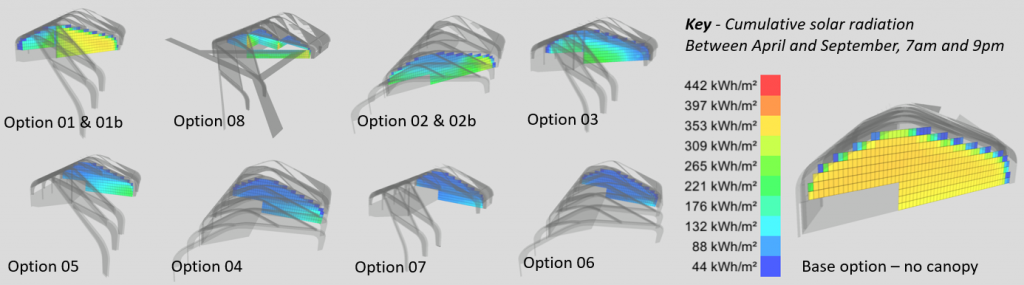
To provide optimal levels of daylight inside the concourse (i.e. increasing the window area), while limiting solar gains (i.e. reducing the window area), an in-house tool developed by the Facades team, called Arup Solar, was employed (Figure 12). This tool aims to investigate the relationships between envelope features (e.g. window to wall ratios, g-values, shading design, etc.) and cooling strategies as well as identifying potential opportunities for renewable solar energy production. In this case, the tool played an important role in fine tuning the window-to-wall ratio and selection of solar control & visual parameters of the glass (i.e. also in competition of interests): Visual Light Transmittance and g-value respectively. Arup Solar was also used to explore various shading strategies in the west façade, and to inform the articulation of the north & south canopies and its relationship with the adjacent facades to minimise the solar gains inside the concourse at critical time periods.
6. Innovative workflows and digital tools
The successful design outcomes and achievements to date, such as the BREEAM Outstanding certification, the 120-years life-span glued laminated timber portal frames and the rationalisation of the roof promoting DfMA strategies were possible due to a committed design team working collaboratively. This collaboration across disciplines and the advanced digital tools & innovative workflows involved were fundamental for the fine tuning of design and performance parameters that, in some cases, needed an engineered approach solution.
Innovative design results from innovative design methods. This section will describe the main qualities of the roof and the methods, processes and analytic tools that have been used to deliver them. In so doing, it is hoped this paper will reinforce the value of a holistic design approach and give examples of innovative software workflows for both design development and design validation in application.
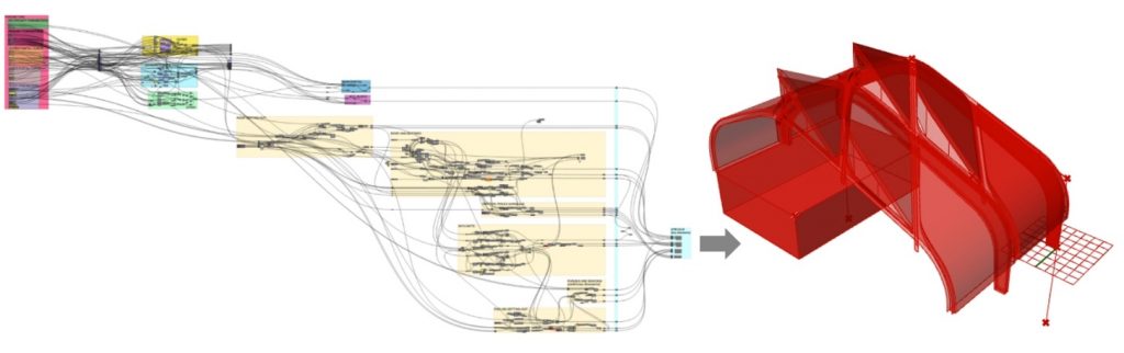
The geometry of the envelope (Figure 13) was developed using Grasshopper (GH) within Rhino (Figure 14), a popular visual scripting platform among engineers and designers. This tool allowed the team to build a Parametric Model based on geometrical relationships between its elements, focusing on the logic and principles rather than a manual modelling exercise. This allowed a thorough rationalisation process that resulted in a simplified geometry and interfaces based on planar, cylindrical and ruled surfaces. Thus ensuring that the smooth and dynamic envelope can be built using standard systems and fabrication methods.
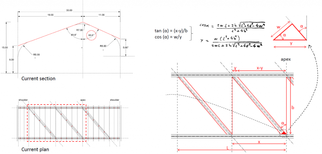
The diagram below shows an overview of the GH script. Here, the key design inputs are defined on the left-hand side, which then feed a series of clusters that hold the logic of the geometry. These clusters are dependant of each other, meaning that the whole geometry responds harmonically to the design input updates following the design rules defined. The outcome of this process, on the right-hand side) is a design iteration, that can be exported in a Cad format to be used elsewhere by others.
Following a traditional workflow, the different disciplines in the design team would develop design models in parallel and hold coordination workshops to discuss discrepancies and negotiate possible solutions, aiming for an alignment across the various models by the end of that process (i.e. typically a design stage). This can be a complex process specially in large projects where large teams and disciplines are involved.
There is certainly room for improvement in this regard and the design team of HS2 Interchange implemented a new innovative practice to improve this multidisciplinary collaboration. The aim was to enhance the Parametric Model with inputs from the various disciplines and to do this in a quick, manageable and efficient way. Speckle, an open source data platform for AEC (Figure 15) was used to connect the various tools involved across disciplines to extract and provide relevant design data. This new way of coordinating and collaborating with others by streaming project data between people did not rely on traditional files but on a seamless dataflow that enabled a more agile and responsive iterative design process.
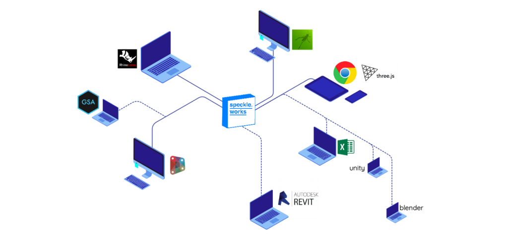
Speckle data lives in the cloud. This allows for data transfer not only from one software to another in a local machine, but also across networks and various web platforms. The data which is sent through Speckle is fully in Arup’s control but rather than having one centralised server, this allows greater flexibility in setting up the desired workflow. This technology is deployed by Arup in a proprietary cloud solution where access is granted using the same high security protocols as per other corporate solutions such as SharePoint. In addition, only users with an account that have been given permission to access relevant data would be able to do so. Providing thus a reliable and secure solution.
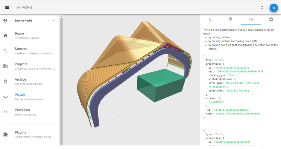
The data in Speckle was managed, inspected and visualised from the web app (Figure 16) or sent to / received form the relevant clients as required such as Rhino (3D modelling), Revit (BIM documentation) or GSA (structural analysis). The dataflow used for the development of the envelope in HS2 Interchange involved Architecture, Structures and Facades disciplines. Here, Architecture was in control of the massing and logic of the design intent. This was then streamed to Speckle so Structures and Facades could develop their design based on this input, that is, the primary portal frames and envelope rationalisation + secondary structure respectively. Likewise, Structures and Facades were sharing and using some of each other’s input such as stresses and deflections from relevant load-cases. And finally, all parties could share feedback in order to refine the parameters of this seamless workflow to design the envelope of the station in a truly collaborative way.
Conclusion / Summary
The roof of the station is a signature design feature; bringing character to the station, aiming to improve the sense of wellbeing for passengers and staff and helping to deliver a sustainable railway. It shows the value of an integrated design approach and demonstrates how using digital design processes can support better collaboration and enable innovation.
To deliver outstanding sustainability, the design team employed digital tools to assess the design and optimise the performance of the roof. As a result, the station will be able to utilise natural light and natural ventilation to control the condition of the concourse space, removing mechanical systems and reducing the consumption of electricity and operational emissions.
To deliver this design there were significant technical barriers to overcome, for example the durability requirement for all structural materials. The integrated design team was able to draw upon diverse skills to challenge existing codes of practice and create innovative design solutions. The use of digital data tools enabled this collaboration and generated a comprehensive body of technical analysis to valid the design proposal.
The design team have positively responded to the HS2 significant ambition to drive innovation in the construction industry. The use of timber in a piece of public infrastructure which has a design life of 120 years appeared at first a daunting task, however the design team believed that both an integrated team and the power of new software tools would allow it to overcome these challenges. The principal learning from the team is that a collective vision is essential. Software and integrated workflows gave the team new abilities to better co-ordinate and analyse to drive the design forward, but the shared ambition set in train by the HS2 Vision was the spark that drove the team forward.
Acknowledgements
- José Márquez Santoyo
- José Hernando
- Grace Reid
- Jonathan Ip
- Miriam Berriochoa
- Gwen Willox
- Jeff Shaw
- Chia Lau
- Jerell Gill
- Mariella Gallo
References
[1] HS2 Interchange BREEAM Outstanding Certification: BREEAM (Building Research Establishment Environmental Assessment Methodology) is an international scheme that provides independent third-party certification of the assessment of the sustainable performance of buildings, master planning and infrastructure projects. BREEAM ‘Outstanding’ is the highest certification, less than 1% of UK new non-domestic buildings achieve this rating. https://www.arup.com/news-and-events/hs2-interchange-station-becomes-first-railway-station-to-achieve-sustainability-certification
[2] HS2 Design Vision and Design Vision Booklet
[3] HS2 Environmental Sustainability Policy and on the Government website.
[4] HS2 Technical Specification, (Chapter 12)
Peer review
- Hala Lloyd, Lead Architect (Curzon)HS2 Ltd
- Jiten Davdra, Head of Engineering and Environment (Stations)HS2 Ltd