Infraworks models to assist with construction sequencing and planning
Autodesk Software package InfraWorks is a 3D Infrastructure planning and design tool which is being used to model specific areas of the High Speed Two (HS2) proposed route and the proposed construction sequences respectively. This paper focuses on the creation of the models, data processing, material volume reports and the benefits that these models have presented.
The models produced have created a visual platform to review the integration of temporary works and permanent works for these large areas of the HS2 Project. Video flythroughs that have been created have also provided the HS2 Project Team with a valuable tool to present the scheme to their client and for use in public consultations.
The paper discusses how the designer is using advanced software to undertake detailed planning at pre-construction stage and how this is helping to eliminate risk items, understand areas which pose the greatest risk and how risk can be mitigated. On the surface, the learning legacy of this study is the value in InfraWorks as a pre-construction tool and its potential application in future phases of HS2 and projects beyond. Additionally, it further supports the importance of high levels of care and attention at preconstruction phase to further optimise both design and construction phases through careful optioneering.
Taking the time to produce high quality outputs at this stage in the project’s life cycle can have benefits for project stakeholders across the board. The outputs described in this paper are constantly being made easier to produce through the development of software such as InfraWorks. This is an area the industry would do well to keep its attention on in the coming years.
The models produced have created a visual platform to review the integration of temporary works and permanent works for these large areas of the HS2 Project. Video flythroughs that have been created have also provided the HS2 Project Team with a valuable tool to present the scheme to their client and for use in public consultations.
The paper will look to promote how the designer is using advanced software to undertake detailed planning at pre-construction stage and how this is helping to eliminate risk items, understand areas which pose the greatest risk and how risk can be mitigated. On the surface, the learning legacy of this study is the value in InfraWorks as a pre-construction tool and its potential application in future phases of HS2 and projects beyond. Additionally, it further supports the importance of high levels of care and attention at preconstruction phase to further optimise both design and construction phases through careful optioneering.
Taking the time to produce high quality outputs at this stage in the project’s life cycle can have benefits for project stakeholders across the board. The outputs described in this paper are constantly being made easier to produce through the development of software such as InfraWorks. This is an area the industry would do well to keep its attention on in the coming years.

Introduction
This paper is presented as part of the works to deliver the central section of High Speed Two (HS2) Phase One – Lots C2 and C3 – which includes the North Portal Chiltern Tunnels to Brackley and Brackley to South Portal of Long Itchington Wood Green Tunnel, being delivered by the EFKB Integrated Project Team.
The use of computer aided design (CAD) software to develop design details for construction is not a new process and is used by many different industries on a global scale. However, recent advances in digital engineering and current Building Information Modelling (BIM) requirements have resulted in designers using new software and techniques to meet their clients’ digital engineering requirements.
In 2015 KPS (Kier Professional Services) identified that the software, InfraWorks by Autodesk, presented many benefits regarding preliminary design and how digital data could be presented in 3D for infrastructure design. The existing high level of knowledge of other Autodesk products meant that the design team could utilise these skills in collaboration with the InfraWorks software to create intelligent data which would create a Digital Twin for a scheme or asset. In addition to this, it was recognised that this software could be used to develop a series of models which replicated the proposed construction phases for a given project – a 4D Digital Twin.
There are many features and benefits InfraWorks offers over the more traditional and widely used CAD software packages. It facilitates the production of 3D visualisations within a real world context quickly and seamlessly. Combined with the ability to add different stages of construction to the same model, it makes it much easier to communicate a proposed construction process visually. The resulting graphics are clear and simple to understand, meaning any potential areas of concern or possible alternative approaches can be identified early in a project. This has potential cost and safety implications that cannot be over emphasised. The software also has analysis capabilities requiring input from both CAD technicians and engineers. This makes it ideal for use in a team where both these parties have experience working collaboratively.
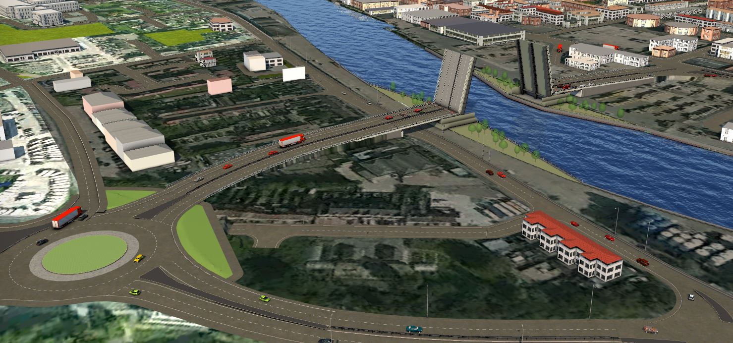
KPS had successfully implemented the use of the software on several projects prior to its use on HS2. These include the Gull Wing in Lowestoft (Lake Lothing Third Crossing) where it was used to produce and develop preliminary design for over 20 proposals. The designs were then used during early stage optioneering and public consultation. Similarly, the software proved invaluable in developing four viaduct options for crossing the environmentally sensitive Wensum Valley as part of the proposed Norwich Western Link. Another high-profile application was the early stage optioneering for Great Yarmouth Third River Crossing. See Figure 1 below for an example of the visualisations produced for this scheme.
In January 2019 KPS suggested to the EKFB HS2 Project Team that the use of InfraWorks could help in their early stage construction sequencing and planning. It was agreed that KPS (the modellers) would undertake two test models and that these would then be presented to the project teams and the C2 and C3 Section Directors.
InfraWorks 4D Tests
It was agreed that the best test for this software and its proposed use was to choose two areas that had already been identified as being challenging to build.
The two areas chosen were:
Section C2 Brackley Road and the C2 Thame Valley Viaduct.
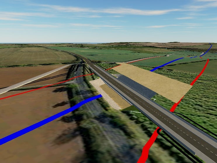
Brackley Road
The HS2 Project team provided a scope which detailed the main outputs and elements they required from the model:
- The site access road
- The haul road
- The permanent works with the ability to show staging of construction with access requirements (ramps down to areas of cut)
- Public traffic flow staging
- Piling platforms
- Crane platforms
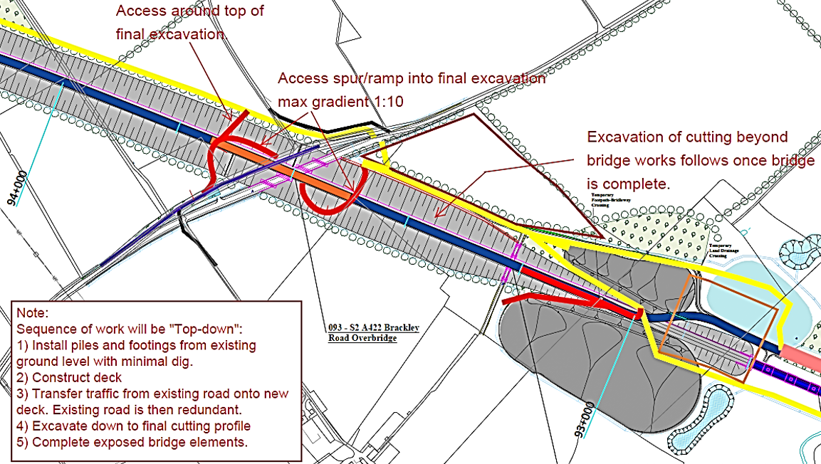
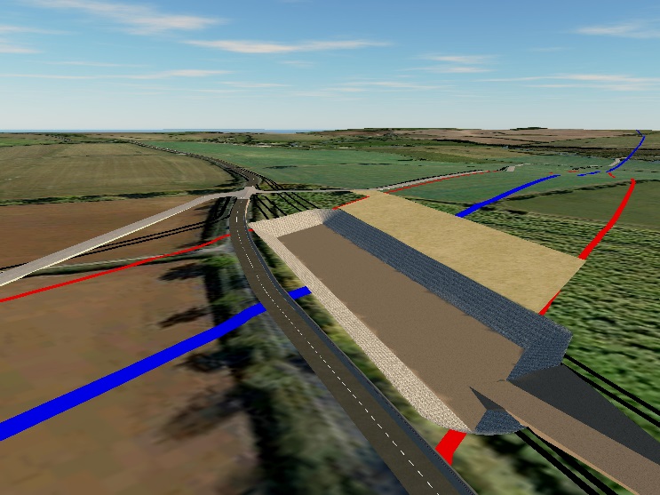
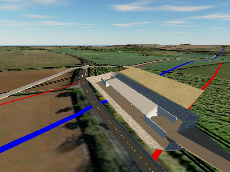
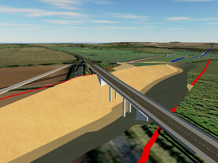
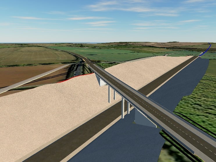
It was advised that a top down construction technique would be used for the new Brackley Road Bridge and a brief sequence provided to the modellers. This would provide the basis of the digital 4D sequencing. At this stage of the project only outline PDF drawings were available. This information provided sufficient detail for the IW Test model to be produced.
One model was created which included five separate views (one for each construction phase). Excerpts of each are as shown below in Figures 3 to 7.
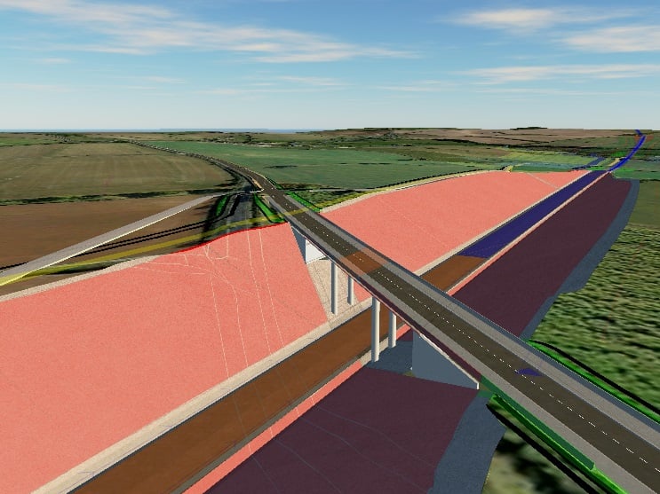
To demonstrate how the model aligns with the proposed scheme design in this area, a 2D surface overlay was created from the PDF. This was then scaled and imported to InfraWorks. Once imported it can be turned on or off (when turned on the overlay is draped over the model surface). This provides a further visual of the full design proposal in this area, as shown in Figure 8.
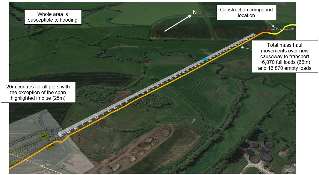
Thame Valley Viaduct
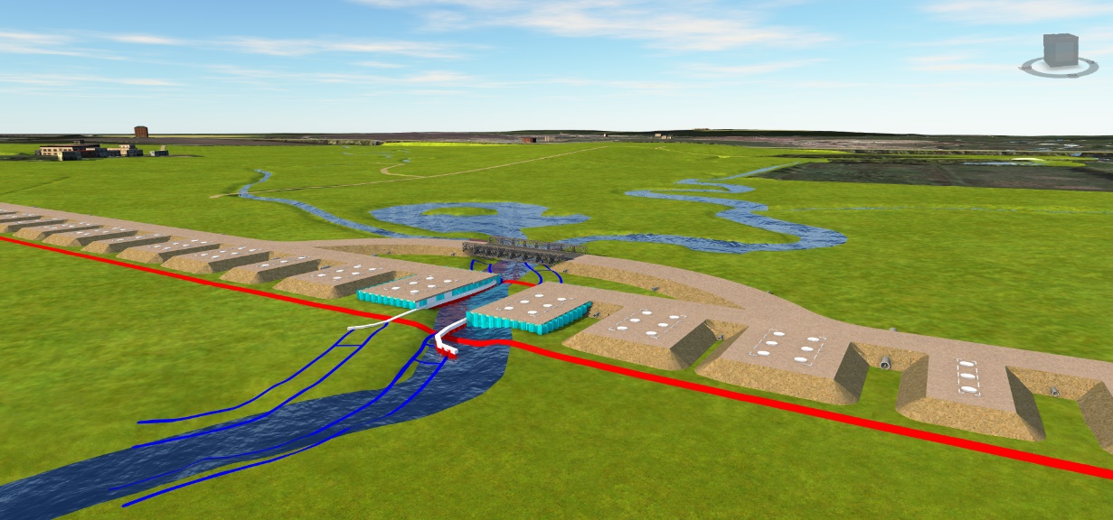
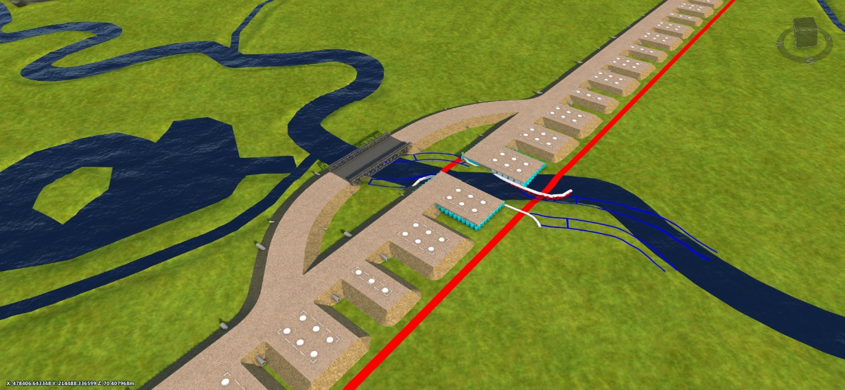
The Project Team advised that the second item of interest was the Thame Valley Viaduct, specifically the site access and piling platforms required for the viaduct piers. The proposed viaduct spans a floodplain and therefore a causeway is required for both mass haul and site access traffic. Additionally, branches leading out from the causeway act as piling platforms for each of the pier foundations.
The causeway needed to stay within the Limits of Land to be Acquired or Used (LLAU) which at this location is 15m from viaduct centreline.
In addition to the above, the causeway needed to have sufficient culverts to ensure it did not impede the flow of the River Thame when in flood.
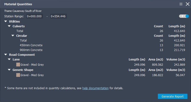
The purpose of modelling this in InfraWorks was to accurately estimate the amount of fill and number of culverts required for the causeway so that it could be covered in the budget price and programme. This model would also provide the Project Team with preliminary information and details to start consultation with the EA and assist with consent applications. The use of InfraWorks allows this information to be obtained faster, both reducing design costs and facilitating earlier communications with the relevant parties.
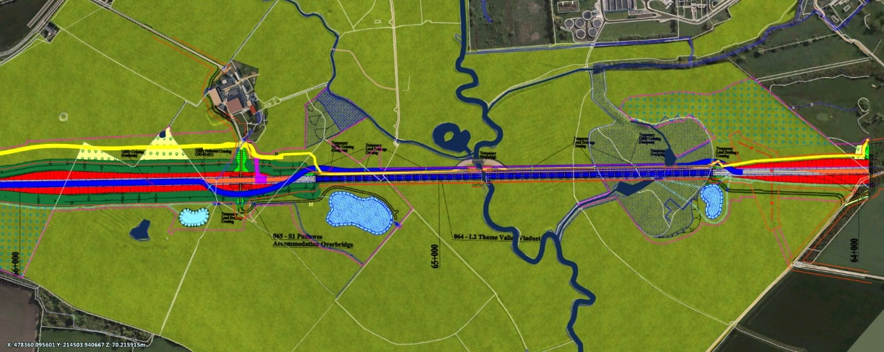
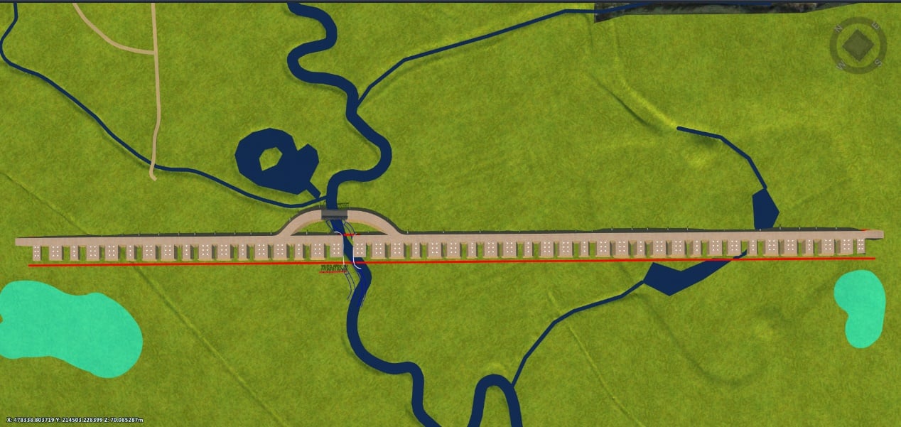
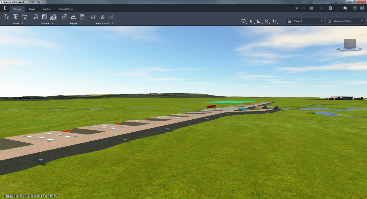
At this location the viaduct design had progressed slightly further than at Brackley Road. The preliminary Revit file were able to be utilised for the structure and the pier foundations and piles isolated. Using this data and again the scheme design for this area an intelligent digital model was produced and the outputs requested from the project team provided. The software tools allowed reports to be generated which provided material quantities for the causeway and culverts, as shown in Figure 13. The model was also able to provide the project team with a detailed overview of the temporary works requirements integrated with the proposed permanent works, as shown in Figures 10, 11, 12,14 and 15. The use of InfraWorks meant that all this information could be sourced from the same place with high quality visual outputs, saving time and improving client satisfaction.
Upon completion of both test models, they were presented to the C2 and C3 Project Teams. The design brief for each asset was discussed first, then the models were used to demonstrate how the requirements of the brief had been met. The digital engineering outputs demonstrated that the Project Teams understood how the InfraWorks software is a digital engineering tool, not just a 3D visualisation package. The response from the Project Teams was very positive and it was immediately acknowledged how the use of InfraWorks could aid early stage planning for construction.
Exemplar reviews
The InfraWorks test models were produced within ten working days. This fast turnaround, coupled with valuable data outputs, led to the Project Team requesting further modelling to support outputs during the Exemplar Review process.
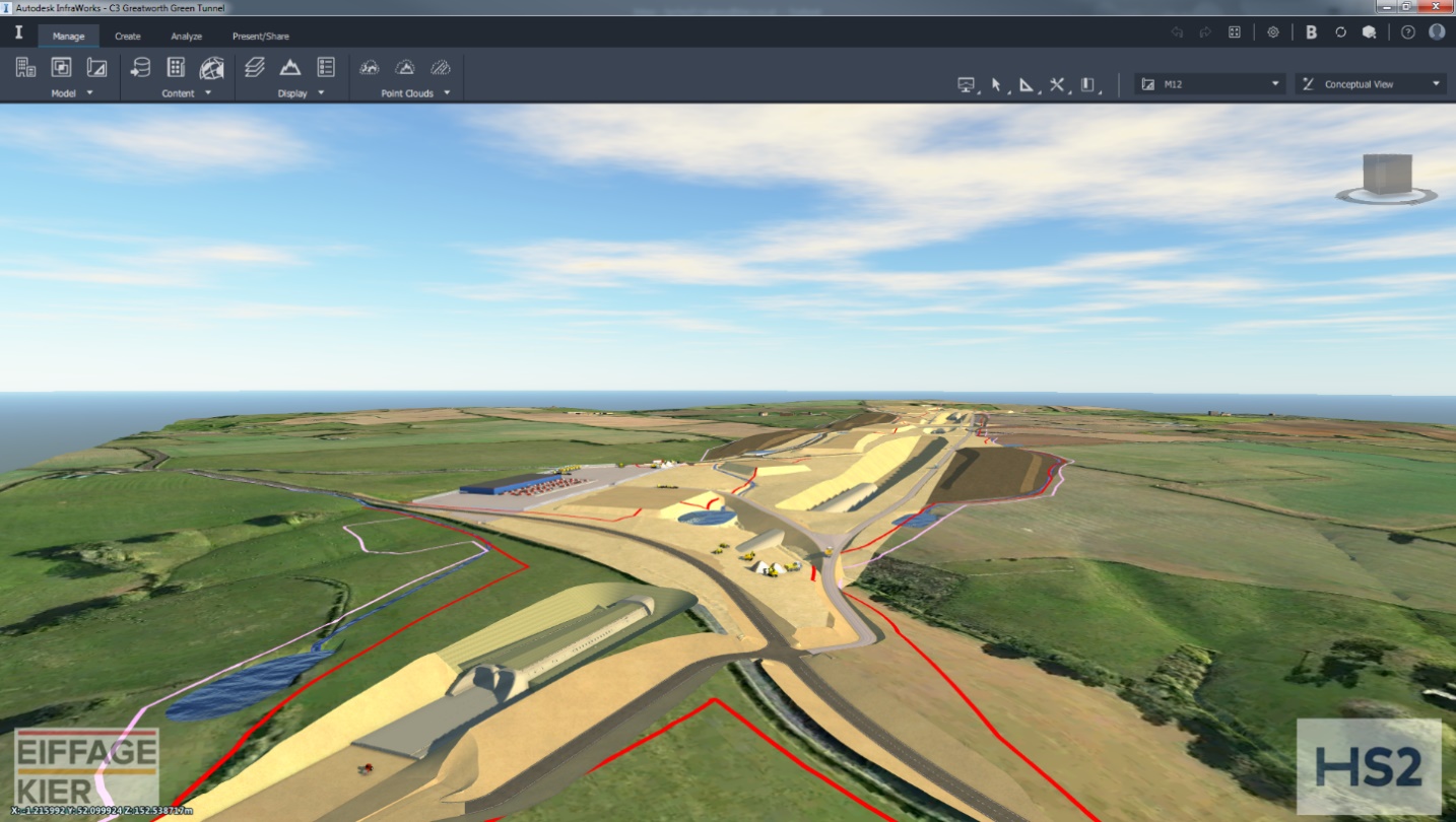
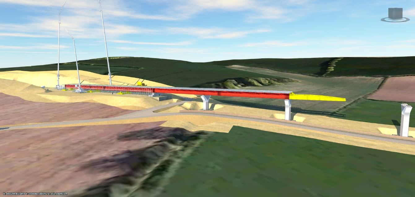
The first asset to be modelled was the C3 Greatworth Green Tunnel.
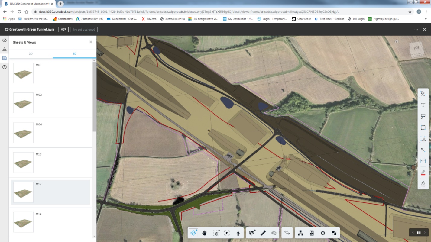
The brief for this asset was to produce a model which incorporated 14 separate phases, communicated to the modellers with marked up PDF drawings. Each sheet clearly indicated which elements will be constructed at each stage. An example is as shown below in Figure 16.
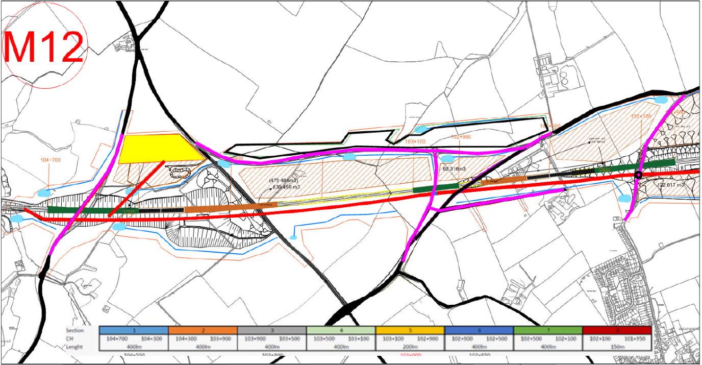
From the marked-up plans detailed views for each phase were created. Figure 17 below is a model view for the sheet M12 shown above.
Each Phase was modelled to reflect the exact requirements communicated by the Project Team. The main challenge for the modellers was that the Revit model provided incorporated the whole tunnel. The model had to be interrogated and sliced up to replicate each phase. Once complete each one of these phases had to be imported into InfraWorks.
Once each phase was complete it was shared with the Project Team using Autodesk BIM360, a cloud-based document management tool.
This meant that the Project Team could review each phase as soon as it was completed, interrogate the model and feedback any comments.
In addition to being able to view the models within BIM360, we could also share the Civils 3D Drawings, cut and fill volumes, images and video fly-throughs which had all been generated as outputs from InfraWorks. The BIM360 dashboard is as shown below in Figure 21.
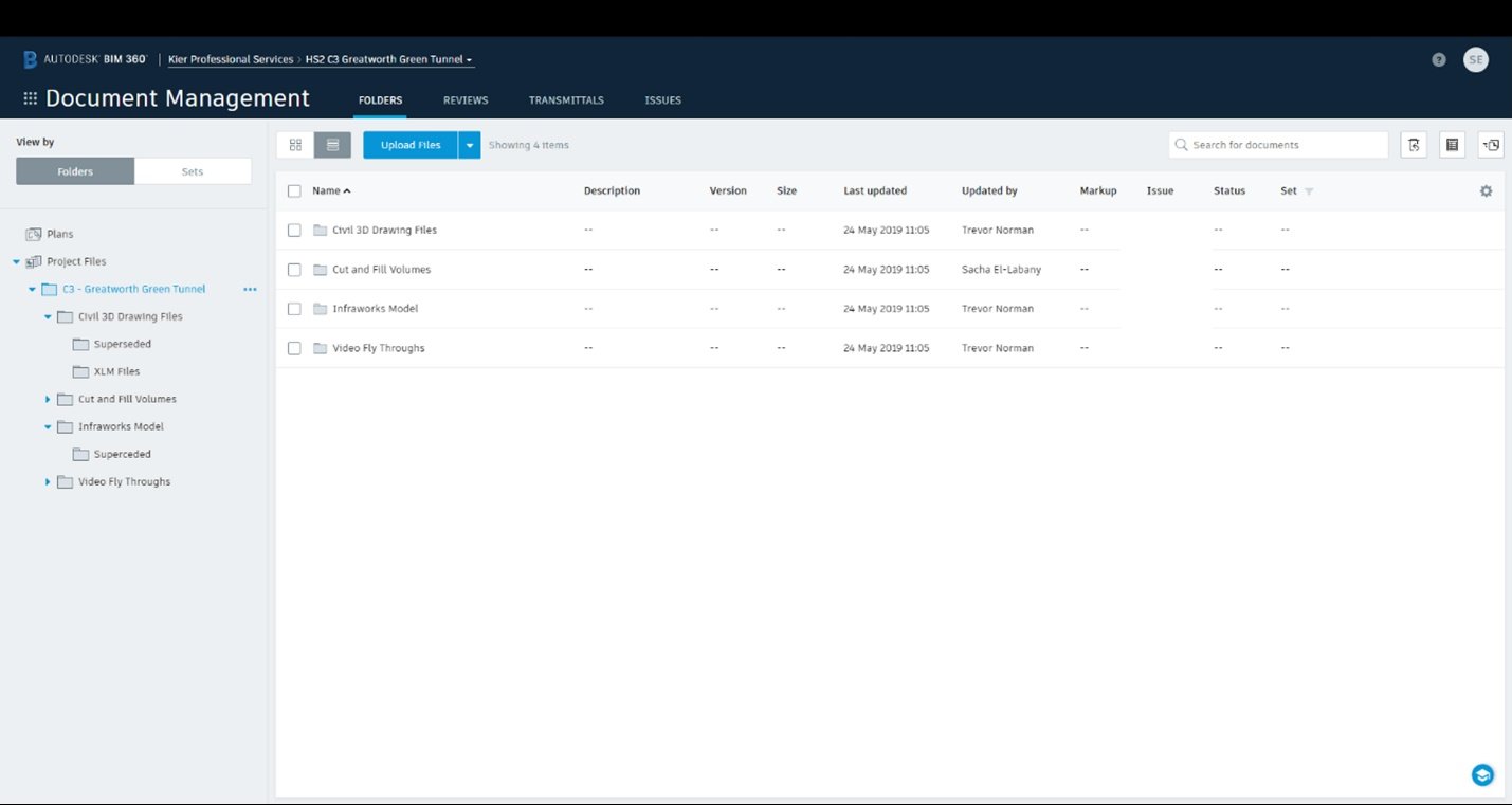
The images, videos and data were then used by the Project Team for consultations and formed a major part for the exemplar reviews with HS2. It provided the Project Team with a clear and detailed overview of the asset and a visual representation of their construction programme.
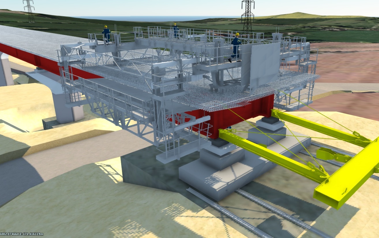
Due to the success of using InfraWorks as a digital engineering tool for 4D modelling, a further request for another asset was received, Wendover Dean Viaduct.
The requirements for the Wendover Dean Viaduct were similar to the Greatworth Green Tunnel. The Project Team required detailed construction phasing over 19 phases. However, Wendover Dean Viaduct will be constructed using a deck launching technique. This meant that not only had the Revit model to be interrogated (and sliced / split up to suit the phases), but also the gradient and position of the deck had to be determined when each section was being constructed on the deck launching platform, with the farthest spans being launched first.
The stages were communicated to the modellers from the Project Team via a detailed spreadsheet and PDF drawings were provided for the deck launching equipment.
As the deck launching equipment was not in a format the modellers could use, these elements were modelled independently.
An additional challenge was presented to model and place the travelling formwork for the bridge deck. An example model was provided and the designers had to amend this to suit the dimensions for the Wendover Dean viaduct deck. The outcome is as shown below in Figure 23.
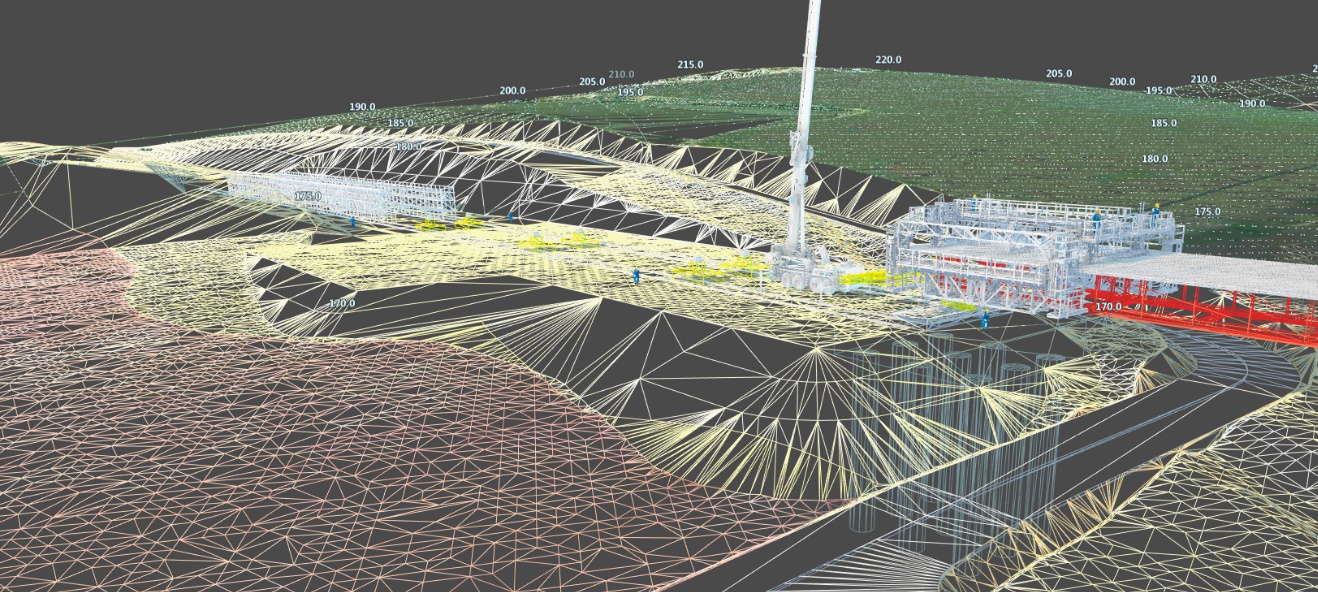
During development of the model a further request from the Project Team to provide LandXML data for the launch platform was issued. As InfraWorks is a digital engineering tool, the model can export valuable data. Using InfraWorks enables the designer to export LandXML files, so this was not a problem. Figure 24 below provides an example of the surfaces created within the model that can be exported.
Upon completion of the 19 phases, the model and outputs were shared with the Project Team using BIM360.
The information and data were used by the Project Team and formed a major part of their constructability reports for the Exemplar Review with HS2. Again, InfraWorks was able to produce multiple high quality outputs from the same model, resulting in faster and better results when compared to other software and techniques.
Integrated Design Solution
The development of powerful design software has been instrumental in the ability for clients and contractors to deliver complex schemes efficiently. The use of this software means that it is now possible to review many different design options which was once not possible.
The modellers identified early-on that the use of these different types of software could provide an integrated design approach to infrastructure projects which at the time was not readily available.
Using the methods described above the provision of preliminary optioneering has been possible, along with detailed design models and data.
The Clients and Stakeholders have also been provided with the opportunity to view their schemes alongside real data. This provides them with a great tool to aid their decision-making processes.
The use of InfraWorks facilitated time savings with a quality and diversity of outputs unique to the software. Combined with file sharing systems such as BIM360 it has shown to be a powerful tool, reducing design costs and offering new methods to communicate and plan construction phases. From this study it is evident that software such as InfraWorks will likely have an important role in high quality infrastructure planning of the future.
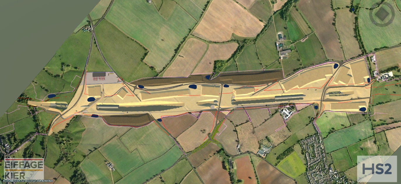
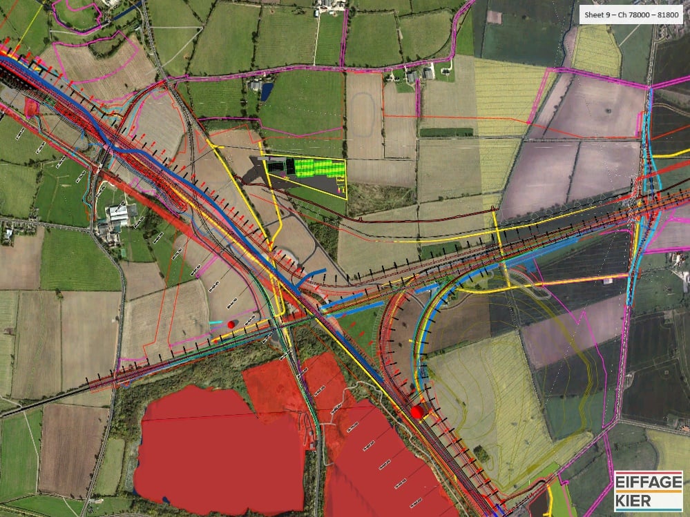
InfraWorks is now used on a daily basis by the EKFB Project Team. It is used to review the interface of temporary works and permanent works and to plan and design the 100km site access road. It has provided those working on the scheme with a very useful tool to visualise and plan this major project. The full route of lots C2 and C3 have now been modelled and include permanent works assets to assist with construction sequencing and phasing. Refer to Figure 25 below for an example.
Peer review
- Luis GonzalezHead of Rail Systems Project Integration, HS2 Ltd