Innovative and Sustainable Twin Arch Solution for High Speed Two Green Tunnels
EKFB-JV will build the Cut and Cover ‘Green Tunnels’ (GTs) as part of the Main Works Civils Contract (MWCC) for the central section of High Speed Two (HS2) Phase One. The design of the GTs has been carried out by ASC-JV. This paper presents the significant benefits of GTs, in terms of savings in cost, time, waste, reduced safety risk profile and improved sustainability. The design of GTs has a key objective to minimize the maintenance requirements over their total length of 6.6km. This type of construction was selected after a rigorous Options Assessment. It is an efficient and innovative structural solution for a cut & cover rail tunnel in relatively high overburden (up to 16m). The paper discusses the benefits that this solution offers covering buildability through reduced complexity in interfaces with other operations and increased level of safety. Other environmental considerations related to construction activities are also presented and discussed.
Introduction
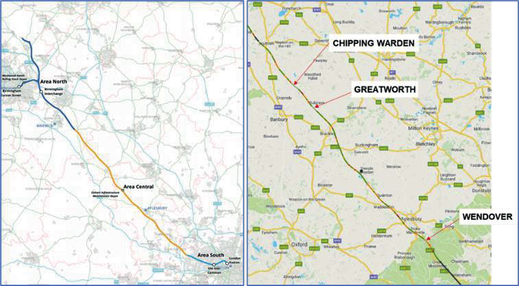
The Main Works Civils Contract (MWCC) for the central section of High Speed Two (HS2) Phase One which includes the North Portal Chiltern Tunnels to Brackley and Brackley to South Portal of Long Itchington Wood Green Tunnel, being is being delivered by the EFKB Integrated Project Team. The detailed design is being delivered by the joint venture between Arcadis, COWI and Setec (ASC). The central section, also known as Area Central (Figure 1), includes the construction of three cut and cover tunnels, referred to as Green Tunnels, which total 6.6km of the alignment and are located at Chipping Warden, Greatworth and Wendover.
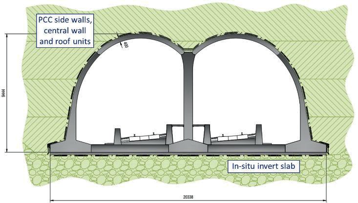
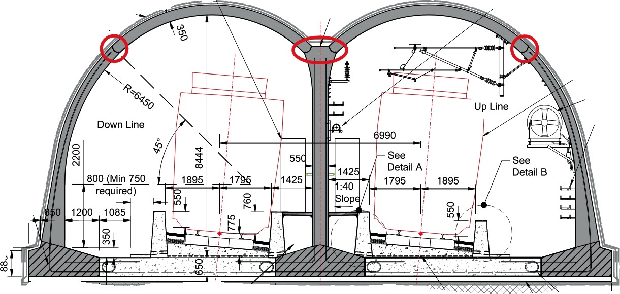
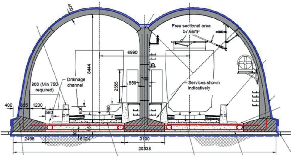
The structural form of the Green Tunnel lining developed through the scheme design phase comprises of a twin arch lining constructed from pre-cast concrete, C50/60 grade, segmental wall and roof units closed with an in-situ concrete base slab (Figure 2). The lining employs innovative loop-to-loop connections between the wall units and base slab and a seated pin joint connection between the arch roof and wall units.
This paper describes the innovative aspects of the twin arch solution (Figure 2) developed at scheme design for the Green Tunnels and the sustainability benefits realised by the twin arch solution, in comparison to the Employer’s Reference Design (ERD) (Figure 3).
Evolution of twin arch solution
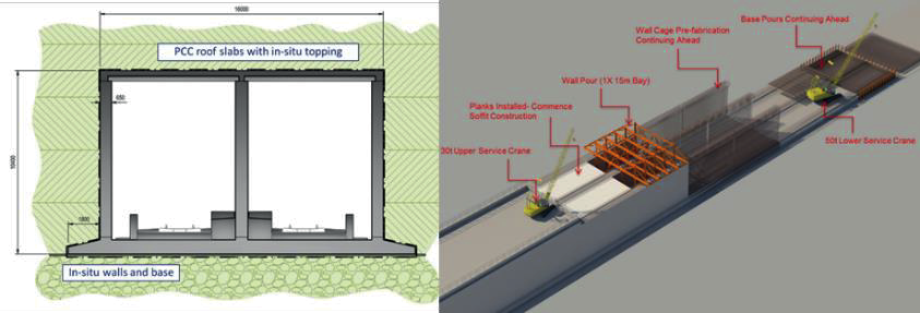
The ERD for the Green Tunnels consisted of a traditional cut and cover box structure comprised of in-situ reinforced concrete walls and roof envisaged to be constructed within an open cutting (Figure 3) The advantages of the ERD included proven construction methodologies with few buildability issues. The design relied on proven methods for waterproofing and fire proofing of the permanent works for the tunnel.
The disadvantages presented by the ERD solution were large volumes of reinforced concrete required for the thick structural elements of the tunnel lining, long construction programme and high volume of construction activities on site for the delivery of the permanent works.
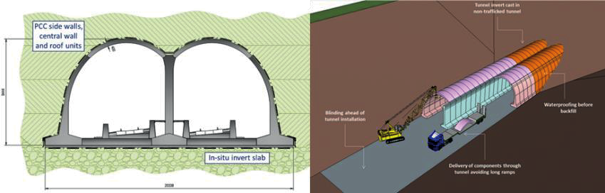
By contrast the twin arch solution proposed by EKFB for scheme design takes advantage of pre-cast construction methodology for the majority of the tunnel lining, maximising off site manufacture of the tunnel structure (Figure 4). The modular construction methodology drives an improved construction rate per linear metre of tunnel lining resulting in a significant reduction in planned construction programme for the Green Tunnels. The arch form of the lining allows for reduction in lining thickness and overall reduction in volume of reinforced concrete required to deliver the Green Tunnels.
The options considered during scheme design were subject to a ‘sifting’ process, based on HS2’s specified Route Development Procedure. The SIFT process included analyses and quantified comparison through scoring of each solution.
The sift process considered and compared a range of criteria for each option including:
- Functionality, Employer’s Requirements and Commitments;
- Whole life cost;
- Construction programme duration and resilience;
- Buildability, precedence and logistics;
- Design for safety, health and well being;
- Sustainability and environmental impact;
- Stakeholder engagement on options;
- Design quality and vision.
Innovative aspects of twin arch solution
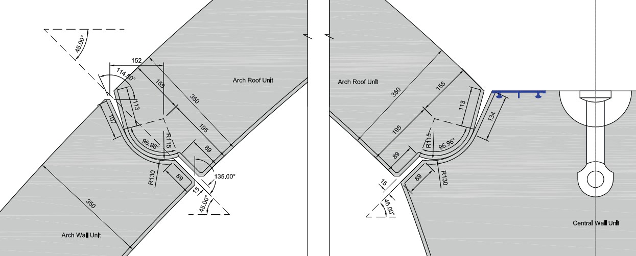
The pre-cast twin arch solution employs novel structural connections between elements of the lining to minimise construction duration of a tunnel ring thus increasing efficiency in the construction of a tunnel. The arch roof section and supporting arch wall unit are connected by an articulated knuckle type joint, referred to as the pin joint (circled in red in Figure 5), free to rotate with no discreet shear connection other than shear interface between the convex and concave concrete profiles of the joint (Figure 6). The form of the joint allows the roof units to be craned into place and sat on the arch wall section of the lining with no need to install shear keys or dowels to connect the units. This allows for a faster construction rate of individual rings for the green tunnel and reduces the planned construction programme for the tunnel lining.
The stability of the arch is generated through development of compressive axial forces through the roof into the arch walls during the backfilling of the tunnel. The compacted backfill generates sufficient axial compression forces to provide stability to the connection under all rotations anticipated for all temporary and permanent construction and operational stages.
The design of the pin joint considers the development of stress concentrations due to different axial forces and rotations under different load combinations throughout the design life of the structure. The analyses of the pin joint captures the non-linear behaviour under different load stages throughout the backfilling operation and during the long-term behaviour of the tunnel lining. The joint has been analysed under critical load combinations including a fire load case for a 170 minute duration fire with maximum temperature of 1200°C. .
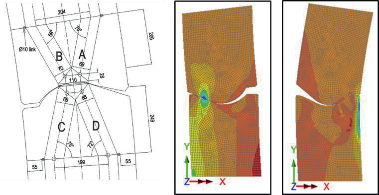
The finite element analyses that has been undertaken to design the pin joint considered the geometrical non-linear behaviour of the connection as the bearing area of joint changes under different magnitudes of rotation.
The analyses made use of the Slide Line function within the FE software package LUSAS to assess the extent of the contact area at different magnitudes of rotation. This allowed for direct extraction of stresses to check against design capacity but also informed an analytical validation check of the design using a strut and tie model (Figure 7).
A rigid moment connection is required between the foundation or footing of the pre-cast wall units and the cast in-situ base slab to resist combined bending, axial and shear actions.
Application of a traditionally calculated lap length for a continuous reinforced concrete section would result in long lengths of exposed rebar protruding from the footing of the pre- cast arch wall. The lengths of rebar for lapping would make transporting and handling the arch wall units difficult and would be vulnerable to damage and require retrofitting.
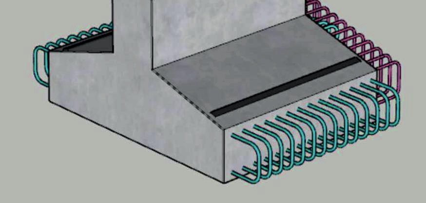
The alternative proposal for the Green Tunnel is a ‘loop-to-loop’ connection comprised of a u-shaped bar cast into the footing to lap the base slab reinforcement to (Figure 8). The U-bar shape is stiffer than single bars and hence would be less prone to damage during transportation, handling and installation. The required lap lengths for the loop-to-loop connection and the base slab have been calculated based on the predicted stresses and have been validated through physical testing on full depth beams under working loads.
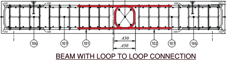
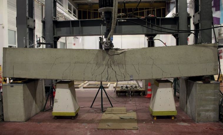
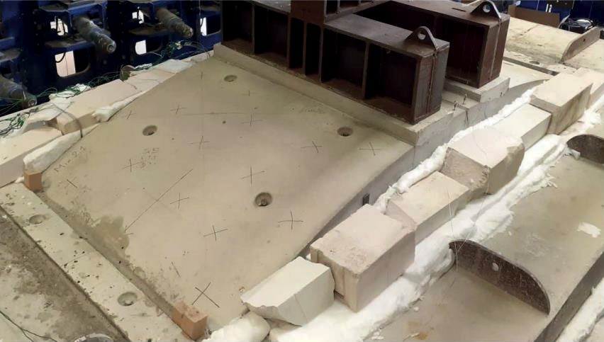
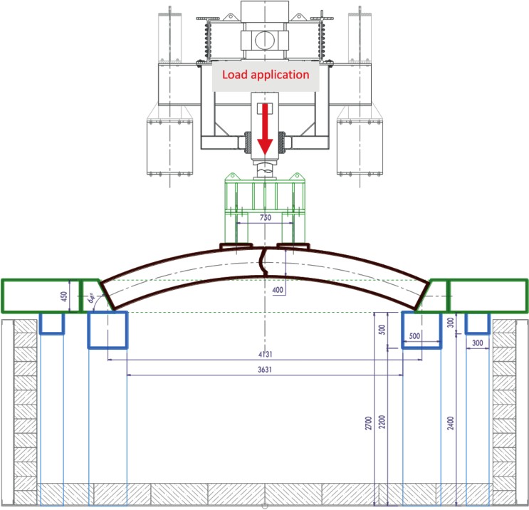
The behaviour of the loop-to-loop connection has been studied and validated through physical full-scale testing (Figure 11) to compare the connection to a monolithically cast reinforced beam joint. The testing demonstrated the loop-to-loop connection exhibited strain hardening behaviour with very similar force-deflection response to a traditionally steel bar reinforced concrete beam for a wide strain range and retained its ductility up to failure.
Figure 10 presents an elevation of test beam with loop to loop reinforcement connection used in the testing. The main objective of the testing was to validate the behaviour of a joint reinforced with a loop-to-loop connection was sufficiently similar to that of a traditionally detailed lapped reinforced joint under loading that the design principles of Eurocode 2 could be applied to the design of the loop joint for the Green Tunnels.
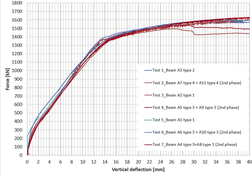
The force vs deflection behaviour exhibited by both sets of test beams, with traditionally detailed reinforcement and the loop-to-loop reinforcement, was very similar in the elastic range. The difference noted in the behaviour was considered within the variability range for concrete beam testing through the elastic range and the behaviour only started to diverge when plastic behaviour developed.
Figure 12 presents the force vs deflection behaviour of the three-point beam tests undertaken on test beams with traditionally reinforced connections (blue) and loop-to-loop connections (red).
The fire design has been facilitated by carrying out an extensive physical fire testing (at CERIB Lab, France) which includes the testing of panels, pre-loaded flat slabs and then half- length full thickness pin-joint segments. The latter test is of great importance to validate the design analysis assumptions for structural stability under loading during and after the fire event and to inform the optimal dosage of polypropylene fibres to be added to the concrete mix. The fire testing of the pin joint specimens was not concluded at the time of writing of this paper.
Sustainability benefits of twin arch solution
Adoption of the pre-cast twin arch solution for the Green Tunnels realises environmental benefits through significant reductions in carbon and greenhouse gas emissions when compared to the ERD box solution. The main contributing factors for the reduction in carbon and emissions are reductions in volume of reinforced concrete for the Green Tunnel permanent works and significant reduction in concreting activities on site due to the pre-cast nature of the arch structure.
A design Life Cycle Assessment (LCA) (EKFB, 2020) [1] was commissioned during the Scheme Design stage of the project to quantify the reduction in carbon and predicted emissions made during construction of each Green Tunnel, comparing the ERD solution (Baseline) and the twin arch scheme design solution (Scheme Design). The conclusions of the Scheme Design LCA are summarised in Table 1 for Greatworth, Chipping Warden and Wendover Green Tunnels.
| Greatworth Green Tunnel | Chipping Warden Green Tunnel | Wendover Green Tunnel | |
|---|---|---|---|
|
Baseline tC02e Product Emissions |
132,102 |
171,106 |
85,549 |
|
Scheme Design tC02e Product Emissions |
116,006 |
104,524 |
70,925 |
|
Reduction tC02e Product Emissions |
-16,096 (12%) |
-66,582 (39%) |
-14,624 (17%) |
The adoption of the pre-cast arch solution improves the planned efficiency on site for the construction of the green tunnel as a greater length of tunnel can be constructed each working month. Adopting the modular pre-cast construction methodology for the twin arch solution significantly reduces the predicted demand for operative hours and increases the planned installation rate of the tunnel when compared to the cast in-situ slip formed construction methodology considered for the ERD.
Table 2 compares the predicted construction durations and operative hour demand on site for the ERD versus the twin arch solution adopted at scheme design and presents the improvements realised by adopting the pre-cast construction methodology.
| ERD Solution In-situ box | Scheme Design Solution Pre-cast Twin Arch | Change ERD vs Scheme Design | |
|---|---|---|---|
|
Predicted Linear metres per month (typical rate) |
60 |
100 |
67% increase |
|
Number of operatives per works front |
70 |
15 |
71% reduction |
|
Operative hours on site |
364,583 |
46,875 |
87% reduction |
The reduction in site work activities will yield environmental benefits to the local community during the site works through an overall reduction to planned construction stage on site and conversely, less disruption and nuisance.
Technical challenges for detailed design & future areas of investigation
The novel connections of the twin arch solution at the pin joint and loop-to-loop were subject to testing during the detailed design stage to validate the behaviour of the connections as considered at scheme design under loading and fire loading.
The behaviour of the structural joints critical to the structural behaviour of the tunnel lining are highly governed by the geometry of the joint hence tolerances for the construction of the tunnel must be controlled to a high degree of accuracy similar to segmental bored tunnel.
Control of tolerances, to the required degree of accuracy, are likely to be difficult to manage for the proposed construction methods. A challenge of the detailed design will be to assess and specify allowable tolerances for all critical construction activities including the manufacture of pre-cast elements, construction of foundation & placement of backfill.
A major risk to the Greatworth & Chipping Warden tunnels is heave pressure acting on the base of the arch caused by the excavation of the over-consolidated clay soils. The magnitude of the heave pressure and the rate at which it would manifest through the construction period and into the long term are difficult to quantify with certainty. Significant ground investigation has been specified and will be used to inform sensitivity analysis via finite element analysis of the effect of heave on the structure.
The twin arch structural solution is most vulnerable during the backfilling of the tunnel, prior to development of axial force through the arch and pin joint, and careful consideration is required for the design of the lining and backfill for this temporary case and, moreover, strict controls must be implemented in the field to avoid uneven loading of the arch. The temporary design case considers backfill to be placed evenly on each side of the tunnel lining with a tolerance of +/- 125mm or maximum 250mm imbalance of backfill level.
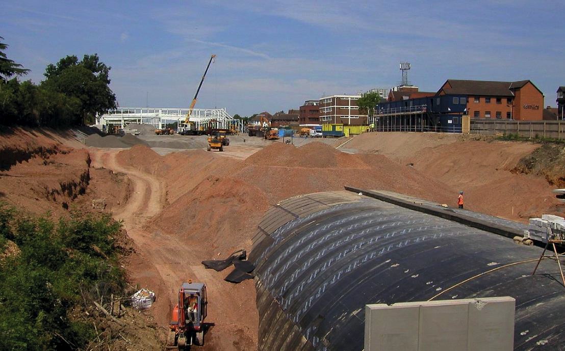
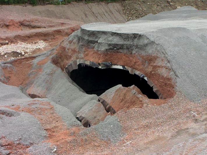
A high-profile tunnel collapse occurred at the Gerard’s Cross tunnel during the backfilling stage of construction (Figure 13). The Gerard’s cross tunnel employed a similar pinned joint in the crown of the arch of a single arch (Figure 13). The exact trigger of the collapse has not been officially reported on due to an ongoing Health and Safety Executive investigation however it is anticipated that the sequence and uneven backfill placement contributed to triggering the collapse.
Publicly available photographs of the Gerrard’s Cross Tunnel before and after collapse indicate that that backfill was built up over the crown, across the pin joint, ahead of backfill at the sides and shoulders of the arch which would have applied higher backfill across the pin joint with low lateral restraint around at the sides of the arch.
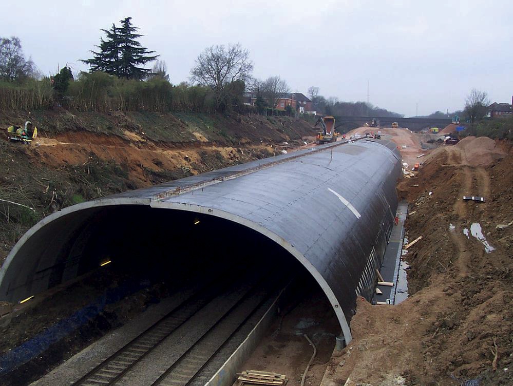
The solution adopted for the Green Tunnels is different to the Gerrard’s Cross tunnel as the pin joints have been moved away from the crown of the arch which will be of benefit during the critical stage of initial backfilling over the top of the crown. Furthermore, the sequence of backfilling has been defined as part of the detailed design and is reliant on the backfilling being progressed at equal levels across the extent of the temporary cutting to limit imbalanced loading being imparted to the tunnel lining.
A monitoring scheme with trigger levels for structural response, ground movements and water pressures has been developed to ensure the ground behaviour and structural response are aligned with the analyses informing the detailed design.
Strict control of the backfilling operation to maintain the tunnel structural response within the defined trigger levels is paramount to the success of the Green Tunnel twin arch solution.
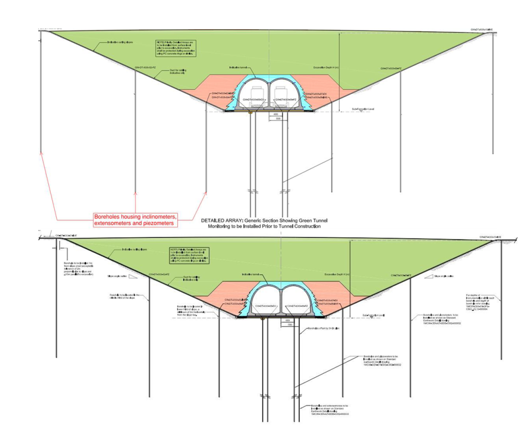
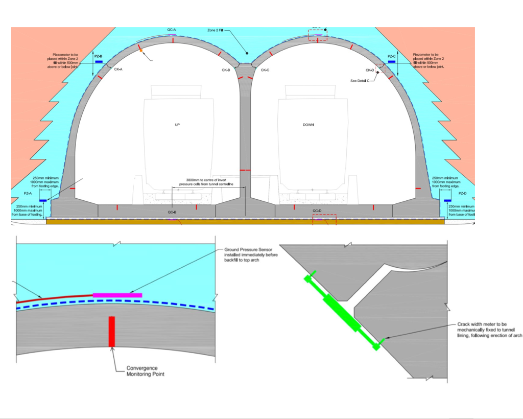
The proposal to manage the strict control on backfilling on site is to adopt tunnelling practices used for the construction of sprayed concrete lined (SCL) mined tunnels, well developed in the past 20 years on major projects in the UK. These include daily Shift Review Group (SRG) meetings to review and analyse monitoring data and to issue a Required Excavation Support Sheet (RESS) for the laying and compacting of the next layers of backfill. Monitoring of both the ground, through in-ground inclinometers, extensometers and piezometers(Figure 14), and the structure, through convergence points, ground pressure sensors and crack meters to measure the pin joint rotation (Figure 15), will also be used to review the response of the tunnel lining to the backfilling operation and compare with predicted behaviour.
The application of underground tunnelling control practices, commonly used for SCL tunnel linings (SRG, RESS),for construction of an open cut and cover tunnel and control of the backfilling operation will serve as an interesting area of future investigation during the construction phase of the GTs.
Summary
The scheme design proposal for the Green Tunnels on Area Central of the Phase One works of High Speed Two was a segmental twin arch structure comprised of modular pre- cast reinforced concrete units. The twin arch Green Tunnel solution adopts a number of innovative structural connections. and the pre-cast nature of the solution yields a number of sustainability benefits when compared with the Employer’s Reference Design which was a typical cut and cover tunnel form comprised of thick cast in-situ elements and limited pre- cast elements:
- Large reduction in overall reinforced concrete volume required for permanent tunnel lining.
- Increased efficiency in terms of advance rate of tunnel lining per month of construction.
- Reduction in operative demand in numbers and hours on site.
- Predicted 25% reduction in greenhouse gas emissions for Greatworth, Chipping Warden and Wendover Green Tunnel construction when compared to ERD
The success of the twin arch solution will require close collaboration between the detailed design team and installation team during the construction stages to review, assess and verify the structural response is aligned with the design expectation.
The use of precast elements is the industry norm for construction of many types of tunnel but typically cut and cover tunnels are constructed using solutions similar to the ERD described in this paper. The twin arch solution proposed for the Green Tunnels demonstrates that pre-cast ring units are applicable also to the construction of cut and cover tunnels where the temporary works footprint allows and the backfilling can be controlled.
Acknowledgments
HS2 for permission to publish this paper during the detailed design stage of the Green Tunnels described.
The contributors to this paper from the ASC joint venture and EKFB construction joint venture namely Matthew Pygott, Zara Rostance, Ralph Yea and Jeremie Martin
Matière TP for valuable input on the performance of the twin arch technology and construction methods from previous projects.
Chris Smith, formally of ASC, for the significant contribution to developing the concept and scheme design for the Twin Arch solution.
References
[1] EKFB. (2020). 1MC07-CEK-EV-REP-C003-000039 – Scheme Design Life Cycle Assessment Report. London: HS2.
Peer review
- Martyn NoakHS2 Ltd
- Ruby KitchingInstitution of Civil Engineers (ICE)