Integral Bridges in HS2
The design of integral bridges may entail significant advantages in some cases as the elimination of bearing devices and structural expansion joints results in a clear improvement of the functionality and safety of the structure in comparison with traditional railway viaducts, while significantly reducing the maintenance liabilities. This is especially relevant when considering the entire life cycle of an infrastructure project, which nowadays typically exceeds a century.
When designing integral bridges, a multidisciplinary approach should be followed, giving especial consideration to the combined behaviour of the structure and the adjacent earthworks at the abutments, due to the seasonal thermal displacements. The cyclic process of deconsolidation of these granular layers at this interface is a critical inherent risk to these structures and, therefore a key factor for the design.
The design gains in complexity, for the specific case of railway bridges, where the requirements imposed by both the track system and route alignment induce additional constrains on the geometry of the structure, limiting, for example, the maximum length or the skew angle along with some other restrictions related to allowable rail displacements.
In the specific case of the High Speed Two project, safety requirements are particularly demanding as trains are expected to operate at speeds exceeding 360km/h. In addition, the track typology is slab, which is much more sensitive to structural displacement compared to ballasted track.
During the detailed design stage, HS2 Technical Services assisted the designers of structures to overcome the above-mentioned challenges, analysing the state-of-the-art and best practices adopted in other high-speed lines around the world and presenting ad-hoc features and solutions which allowed designers to go beyond the standard limits without compromising the operability of the line and the safety and comfort of the passengers and with a minimum impact on the overall cost and programme.
This paper aims to present the most relevant challenges that HS2 designers faced when developing integral railway structures, the proposed solutions from both a civil and track perspective and finally, the lessons learned during the design and construction process.
Introduction
High Speed Two (HS2) is the Government’s scheme for a new, high-speed railway line that connects the cities of London and Birmingham with a connection to the conventional network north of Birmingham.
In that context, HS2 Ltd was created as the non-departmental public body responsible for developing and promoting this project, and the company works to a Development Agreement made with the Secretary of State for Transport.
In order to ensure that the designs of major stations and structures fulfil the local aspirations of different communities and contribute to the natural and built environment, an Independent Design Panel (IDP) was created with experienced members covering all disciplines to independently assist the design challenge. Therefore, the IDP assists HS2 Ltd giving advice, whereas HS2 Ltd works in partnership with a range of organisations (contractors, engineering firms, consultants, etc.) and planning authorities, with the ultimate aim of delivering a high-quality design that is also cost-effective and sustainable.
Within this framework HS2 Ltd’s role is to ensure that:
- The design is safe, efficient buildable and compliant with the requirements of whole life operation and maintenance.
- The design contributes to a sustainable development.
- The design of all visible elements of the built and landscaped environment in both rural and urban areas are sympathetic to their local context, environment, and social setting.
- The design has a culture of cost awareness to give cost / quality decisions which achieve best value for money.
When designing bridging structures, the above-mentioned goals allow HS2 Ltd to give significant freedom to the designers to propose the best solutions for each specific context and situation. The designers must ensure compliance with the relevant HS2 Technical Standards and Specifications, and present cutting-edge designs that minimise disruption to the public during both construction and operation. Additionally, any activity must meet budget and environmental requirements.
General concepts of integral bridges for High Speed Two
As mentioned, High Speed Two will connect London and Birmingham following a 140-mile-long route with more than 100 bridges and viaducts, half of them being integral (fully or semi-integral depending on the case). This aligns with HS2’s Design Vision of providing efficient civil structures that combine low maintenance requirements with aesthetic attributes while ensuring a safe and reliable support for trains at speeds exceeding 300 km/h.
HS2 project: Design speed considered for the design of HS2 structures and track is 360 km/h.
Designing integral bridges has significant advantages as it eliminates bearing devices and structural expansion joints. These elements traditionally require more maintenance, so removing them will result in a lower whole life structural cost when compared with the conventional solution of bridges resting on bearing devices.
Integral structures do not require one specific deck typology or material. Therefore, civil designers can opt for either in-situ, precast or even composite steel-concrete decks depending on where the structure is sited, its specific constraints and use, and other environmental criteria. The choice between precast concrete or steel structure is driven by functional requirements and project economics in the same manner as for traditionally simply supported/continuous bridges.
It is also relevant to note that the concept of integral structures is not revolutionary. However, new materials for bridge design and the increasing demand for longer structures over the last century has made it essential to accommodate structural expansion joins to absorb the deck movements due to the thermal and time-dependent effects.
Worldwide, over the last 30 years, concern about durability of structures has increased significantly. Designers now aim to lengthen the design life of the structures while reducing operational maintenance liabilities, and therefore, the whole life cost.
Codes of practice and most standards have been adapted over years to address those concerns, increasing the durability requirements and also demand for material. This trend is triggering a lower use of structural elements with a design life shorter than the main structure’s as that requires a higher inspection and maintenance regime, but only as long as this is feasible and reasonable from a technical perspective.
In the United Kingdom, until 1995 the Design Manual for Roads and Bridges (DRMB) requirements only covered the “traditional” use of expansion joints to cater for thermal expansion and construction. Yet, as it has been found in many countries, the use of expansion joints has led to durability issues and expensive maintenance liabilities, and although these problems can largely be overcome by appropriate detailing and timely inspection and repair, there is still a cost penalty. That is why in 1995, a new document was added to the DMRB: BD 57 – Design for Durability (current CD 350 – The Design of Highway Structures). This standard related mainly to the design of concrete structural elements, but it also introduced, the direction to designers to consider integral construction for all highway bridges up to 60m overall length and with skews not exceeding 30 degrees[1].
In BA 42/96 – The Design of Integral Bridges (withdrawn since 2018) it is possible to find the definition of integral bridges as “a bridge with integral abutments”. An integral abutment was defined as “a bridge abutment connected to the bridge deck without any movement joint for expansion or contraction of the deck”. In this standard, seven different types of integral abutments were outlined, although this paper aims to cover the fully integral[2] and the semi-integral[3] solutions as they are the solutions most used today.
In general, in those situations where this solution may be a design option, integral bridges tend to be more economical than the traditional solutions. Not only from a construction point of view, but also and very specially from a maintenance perspective: bearing devices and expansion joints are expensive and their repair and/or substitution are onerous in terms of cost and track possession, the latter has high impacts in a railway line time. Besides that, the most common corrosion issues are usually related to salt water running down from the deck surface through the joints, which can be solved, or at least mitigated, by designing integral bridges.
Having said this, and despite this solution’s clear benefits, there are a number of issues related to integral bridge design and construction which require designers to pay special attention during the design stage. These include time-dependent effects such as concrete creep and shrinkage, temperature variation and seismic effects and geotechnical issues including soil-structure interaction.
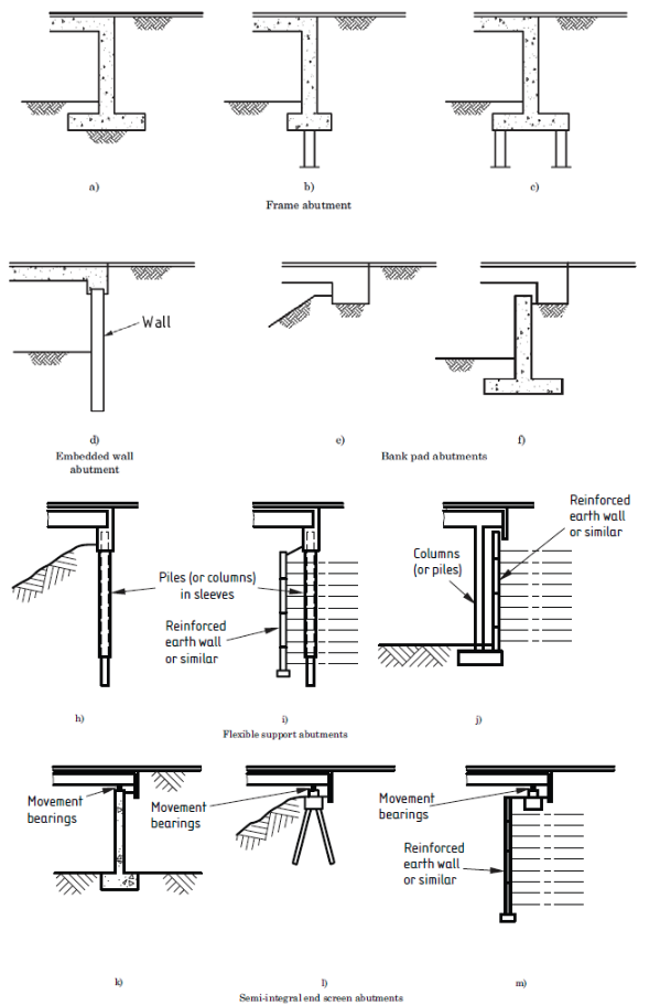
When designing integral structures, it is important to consider several aspects that influence the behaviour of the structure. Some are summarised as follows:
- Integral abutments are normally much stiffer than adjacent piers and, therefore, attract a larger part of both the longitudinal and transverse inertia loads from the superstructure, so they cannot be designed using a tributary mass approach.
- Earthquake forces on the abutments of long and wide bridges, when applicable, can be significant and, for that reason, special consideration is required when detailing the diaphragm wall and foundations to resist these forces.
- Backfilling behind the abutment with densely compacted non-cohesive soils is pivotal and may reduce the effective longitudinal displacement at abutments.
- The final integral abutment form is dictated mainly by geotechnical considerations. Detailing of the abutment-to-deck joint requires special attention for precast concrete superstructures, with particular focus on the embedment of precast concrete beams into the abutment, the reinforcement detail for the connection between the abutment and the precast beams, and the detailed construction staging of beams and abutments to adequately manage beam-end rotations due to creep and shrinkage.
This sketch shows the main difference between a traditional abutment and an integral one, the latter showing where thermal effects and horizontal loadings have a crucial effect on the combined behaviour of the abutment-earthworks transition.
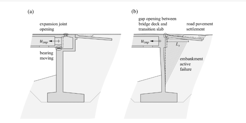
Main implications for the railway / high-speed case
The use of integral structures in railway projects has normally been limited to overbridges spanning the tracks and underbridges (generally short structures). However, the benefits of this type of structure have not remained hidden and their use is becoming more frequent to cover longer span lengths.
For railway structures, it is important to consider that both rolling stock and the track system have very specific demands that will impose constraints on typology and structure dimensions. Given their nature, high-speed trains are very sensitive to any variation in the quality of the supporting structure and at the same time raise the passenger’s demands in terms of comfort. Therefore, thorough attention must be given to the Rail Structure Interaction analysis with the objective of avoiding undesired track stresses and displacements which are not compatible with a safe operation of the line.
The longitudinal forces that act on the continuous rail as a result of horizontal deformation must not exceed a limiting value. This can be achieved by maintaining a well-defined boundary condition and ensuring a minimum stiffness for the substructure and limiting the free expansion length, under all circumstances.
The dedicated analysis increases the acceptability of longer structures which induce greater deformations and can also be used as verification whilst maintaining permissible rail stresses and displacements.
When undertaking this type of assessment, the key parameters to be considered for the design of integral railways bridges are as follows:
- Track-form typology (ballast vs slab track). This should be decided in advance of detailed design, especially if the designer’s intention is to go beyond the normal practice in terms of expandable length and/or skew angle.
HS2 Project: The track-form chosen is precast slab track from PORR AG.
- Length of the structure. This parameter will influence the longitudinal displacement at the abutments due to thermal and rheological effects. And in the case of skewed structures, discussed later, it also has a decisive impact on the transversal displacement.

- Flexibility of the intermediate supports. A high structure (supported by tall piers) will generally be longitudinally more flexible, and therefore able to accommodate longitudinal displacements. Foundation type and ground conditions are also an important consideration at this point. The overall system, including superstructure and substructure, needs to be assessed holistically.
HS2 Project: Most of the structures are considered low or very low bridges (with a height that ranges between 5 and 10m) so making use of this solution has mostly not been feasible.
- Deck width. This parameter is not normally considered as viaducts for high-speed lines generally have a similar width which comprises two tracks.
HS2 Project: Structures need to carry up to four tracks (that implies an overall width in the range of 22m). As will be shown later in the case studies, this width may create unacceptable differential movements on the outer tracks due to temperature variation of the whole deck.
- Skew angle. Integral structures of up to 20–30m are very efficient for crossing highways or other lineal elements. Therefore, structures may need a certain skew angle, to minimise the length of the internal spans in some instances. The effect of the skew angle will be analysed closely in the next section.
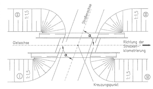
Additional constraints posed by skewed crossings
The skew angle impacts on the overall behaviour of integral structures imposing some additional constraints:
- The first one is geometric. When the abutment (or any intermediate joint) is skewed, accommodating the angle to lay the slab track, due to its monolithic nature makes the design excessively complex, see below.
HS2 Project: In the case of HS2 structures, as the track typology is slab track, a number of short and highly skewed underbridges, that would traditionally have been acceptable for ballasted track, have been adapted in the abutment area to provide an orthogonal abutment interface with the backfill in order to make them compatible with slab track.
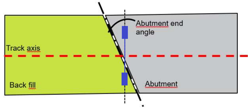
- If bridges have a high level of skew, a scenario where the two wheels of the same axis of a train may be located on different supporting structures (with different stiffness) may happen, as shown in the image below (one wheel on the bridge deck and the other on the abutment). This situation may cause track twist not compatible with the operational requirements.
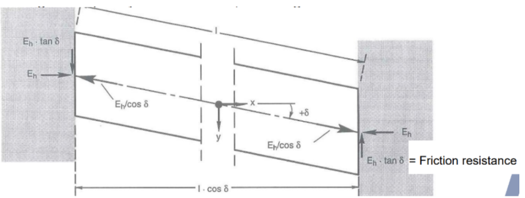
- Secondly, another constraint imposed by a skew angle is the maximum lateral displacements at the abutments. In these cases, the deck expansion and contraction can cause friction forces on the abutment walls. If this sliding component cannot be resisted by friction in the backfill (due to a low angle of internal friction and / or to large skew) or by the foundation, the bridge may rotate and generate high transversal differential movements between the abutment and the backfill.
As mentioned above, BD 57 – Design for Durability (current CD 350 – The Design of Highway Structures) states that integral construction should not be used if skew angles deviate more than 30 degrees. However, surveys of current practice have revealed that designers have proposed fully integral bridges when skew angles are up to or slightly exceed this value; whereas semi-integral bridges are rarely designed when skew angles are above about 20 degrees. However, it is important to note that road bridges are much less constrained than railway structures and therefore, 30 degrees might be excessive in the case of a high-speed railway bridge.
This difference in skew angle limits between fully and semi-integral structures are based on the fact that semi-integral bridges are typically supported by bearings at the abutments and therefore a high skew angle would not be compatible with train operation due to excessive transversal displacements in those areas.
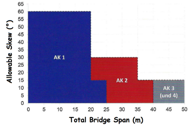
When dealing with integral skew structures, German Regulations provide a useful categorisation based on the total length and the skew angle. As shown below, both parameters are linked: the longer the structure, the more limited the acceptable skew angle.
It is completely understandable that there might be situations where the circumstances or alignment constraints, for example, prevent from limiting the skew crossings, but in general these situations should be avoided as reasonably practicable, in order to reduce the above-mentioned challenges. This is even more pertinent for railway structures as trains run through structures with very different behaviours, and the subsequent implications on safety, operability and user comfort.
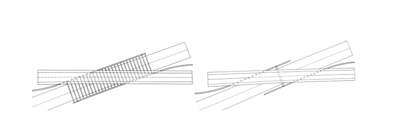
Although it is not in this technical paper’s scope to cover skew crossings, there are several ways to span highly skewed crossings. Some include:
- Pergolas can avoid lengthy spans, by placing beams perpendicular to the axis of the obstacle needing to be crossed. This makes the deck area bigger than strictly required but reduces the flexural demand.
- Intermediate supports also can reduce the span of the structure.
Guidelines for the design of integral bridges
As previously mentioned, sometimes an integral bridge may be beneficial and can provide a perfectly valid solution, but the designer must be aware of the implications below.
Creep and shrinkage
Creep and shrinkage need to be considered together as they are dependent on similar parameters. They are both time-dependent and can cause axial shortening and rotation at the deck ends, inducing significant stresses in the continuous deck, especially with monolithic connections to piers and abutments.
While in traditional simply supported bridges, both structural and non-structural elements such as expansion joints, bearings at piers and abutments accommodate rotations and displacements induced by these effects. (and therefore, reducing or minimising secondary stresses through the additional degrees of freedom), due to the absence of these mechanisms to release structural stresses, secondary effects such as creep, shrinkage and thermal gradient have a significant influence[8] on the behaviour of integral bridges.
HS2 Project: this has been especially relevant in box-structures, pergolas and flyovers where installation sequencing of the different elements (precast beams, cast-in situ deck and walls) has played an important role in order not to exceed deformation limits post-track installation. It is also relevant to highlight that in the design of the HS2 structures, the actual influence of creep and shrinkage has been thoroughly analysed, in order to minimise the use of rail expansion devices (REDs)[9].
Temperature loading
Differential thermal gradients through the deck depth cause significant internal forces and associated stresses that are important to consider when designing decks and integral supports, which are also derived from the constrained rotations.
It is also essential to take into account that, where foundations restrain displacements due to uniform temperature loadings, a considerable axial load will be developed in the deck and transferred into the integral supports.
HS2 Project: in order to optimize the design for specific structures, the thermal load has respected the design life of the structure (120 years return period) but referred to the average bridge temperature of 10°C in contrast to NA + BS EN 1991-1-5 which proposes 0°C for expansion and 20°C for contraction.
The continuity between superstructure and substructure in integral bridges results in the transfer of thermal deformations induced in the bridge deck into the abutment walls, piles, and surrounding soil.
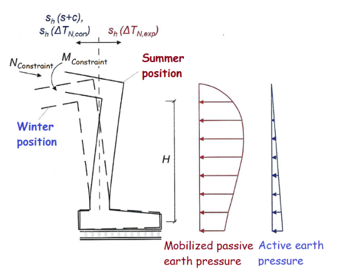
The complex non-linear soil-structure interaction resulting from these deformations encompasses secondary stresses resulting from creep, shrinkage and other effects. The magnitude and mode of deformations and both the overall soil and structural responses are heavily influenced by the level of compaction of the granular fill behind the abutment walls and adjacent to the piles, along with the relative flexural stiffness of the bridge deck, abutment wall and foundation piles, and by the lateral pressure of soil behind the wall and confining stress level in the soil.
HS2 Project: total movements of the abutment wall (contraction plus expansion) of 20mm are considered acceptable without the need of transition slabs or other mitigation measures. This is a compromise between the abutment wall design (in terms of the interface between the abutment wall and the earthworks transition) and the affection to the rail stress due to rail structure interaction (which is minimal with the mentioned 20mm displacement).
Actual earth pressure is generally lower than the full passive pressure and should be calculated using a soil-spring model with realistic soil parameters.
HS2 Project: HS2 has explored the use of geotextiles (e.g., Enkadrain[11]) which fill the gap with an elastic material and are permeable to water for drainage purposes.
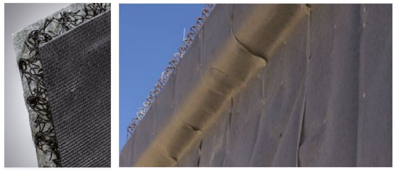
Generally, lower and upper bound analyses using the shallowest and deepest soil layers respectively, should be carried out to determine the structure sensitivity to the soil. These parameters should be confirmed right before the start of the works in site by doing corresponding geotechnical investigations.
Some public administrations define different levels of geotechnical assessments by the characteristics of the bridge (e.g., length and skew angle as shown in Figure 7).
Approaching systems (transitions structure-earthworks)
The approaching system of an integral bridge typically consists of the abutment backfill, a reinforced concrete slab (when installed) and the foundation soil.
Although it is not normal practice in projects in the UK, the use of approaching slabs is relatively common in railway projects in countries such as Germany, Spain, France, etc. The intended functions of an approaching slab are:
- To reduce the differential stiffness between the structure and their accesses.
- To provide a ramp for the differential settlement between the abutment and the embankment.
- To seal against water percolation and erosion of the backfill material.
A void between the backfill and the abutment is likely to develop in integral bridges due to abutment movement. However, when an approach slab is used, this potential ‘bump’ occurs at the end of the approach slab, where the impact on the structure behaviour is far less concerning.
A common design rule is that the zone of influence extends from the abutment to a distance equal to twice the height of the abutment, and therefore the length of the approach slabs should be two to three times the height of the abutment.
The approach slab should be positively attached to the backwall by properly anchored reinforcing bars, although a fully fixed connection between the approach slab and the abutment is not entirely recommended. The connection should be detailed to act as a pin with tension steel transferred across the approach span into the backwall of integral and semi-integral abutments. This should also allow for a certain tolerance between the slab and the corbel so that no damage occurs when settling happens.
To ensure efficient performance of the approach system, the following should be carefully considered and addressed during the design and construction of integral bridges:
- The cyclic nature of abutment movement tends to deconsolidate the backfill and, therefore, in the long term, even using very dense backfill won’t prevent this from happening. This explains why approach slabs are normally required to compensate for backfill settlement.
- Detailed settlement analysis should be performed to estimate the level of vertical movement of the bridge and its approaches.
- If large settlement, due to soft or compressible in-situ soils, is expected, soil improvement measures (such as replacement, preloading, vertical drains, and other stabilisation techniques) should be considered. Also, consideration should be given to the construction of the embankment of lightweight materials.
HS2 Project: an “approach slab” is being proposed, but instead of being incorporated into the civil works, it will form part of the slab track design. Figure 12 shows this arrangement.

Serviceability Limit State (SLS)
When defining limits for key parameter limits that govern the design of the integral bridges for railways, it is essential to be clear about serviceability limits and how these affect the serviceability and ultimate limits of the track. It is essential to acknowledge that there are limits for SLS bridge design, that may be an ultimate limit state (ULS) for track design. This becomes relevant when keeping the design consistent.
HS2 Project: Particularly for HS2 structures, when determining the displacement limits that affect track elements, instead of ULS, two SLS load combinations have been used to set up those limits:
- SLS characteristic – 5% probability of being exceeded in 50 years.
- SLS frequent – 5% probability of being exceeded every few weeks.
It is not unknown for SLS to distinguish between reversible and irreversible effects, but none of them should exceed the elastic limits of materials as this may increase the risk of failure.
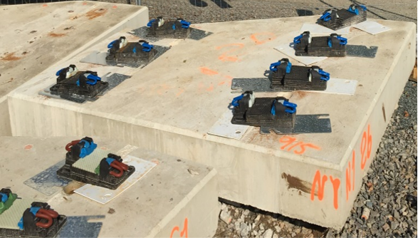
This consideration is crucial when considering the capacity of track fastenings which are expected to cope with the differential transversal displacements caused by the bridge.
As mentioned before, for HS2 using special fastenings with additional capacity in one of the preferred options to mitigate undesired movements at a track level. This allows a design that would not be acceptable otherwise from an operational point of view.
Tailoring of requirements and mitigation measures implemented in the design of the HS2 structures
Some preliminary designs for HS2 included long structures, highly skewed in many cases, and most importantly, integral (or semi-integral) solutions. Therefore, to overcome all the challenges related to these, the designs had to be revisited during the detailed design stage to ensure that they were compatible with a fully operational railway system.
Any redesign of the original solution had to have a minimal impact on programme and cost, HS2 Ltd and the design teams. Also, the contractors, working under those conditions had to find the most cost-effective adaptations and measures to mitigate any potential issues, with regards to both civil and track domains.
A brief summary of the main measures undertaken is outlined as follows.
HS2 Ltd
- Agreement on consideration of SLS for the calculation of displacement limits.
- Adjustment of limits of transversal differential displacement at abutments (or internal structural joints) – From SLS Characteristic +/-2.5mm to +/-5.0mm
- Increase rail stress limit from 92 MPa to 112 MPa when deck bending forces have been considered in the design[12]. Note that this increase becomes even more efficient in integral structures as they tend to have low deck rotation values in comparison with non-integral structures.
Civil Designer
Although some adaptations will be described in the following section with examples, the designers analysed a number of modifications to with the objective of fulfilling the requirements and satisfying track demands. Some of them are described as follows
- Elimination of skewed abutments; in some cases, by means of additional triangular extensions to the deck or by the inclusion of intermediate raft slabs.
- Modification of abutment walls typology in box-structures (from continuous walls to columns, to minimise displacements under thermal actions.
Slab Track Designer
- Incorporation of rail fastenings with enhanced capacity for transversal displacements, to cope with the adjusted requirement granted by HS2. From fastenings allowing + / -1mm of transversal deformation to fastenings allowing up to + / -2.5mm (per fastening). Those fastening to be located at both sides of the joint with a minimum of three pairs each side.
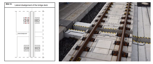
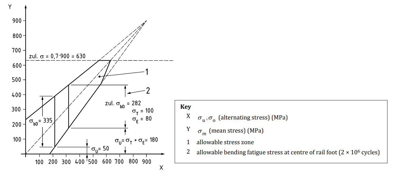
- Verification of additional rail stress created by the transversal displacement on joints where special fastenings are incorporated. Although the use of special fastenings makes possible the increase of the limits for differential transversal displacement between decks or between the abutment and the backfill, this creates additional rail stress due to lateral bending of the rail. This stress needs to be considered together with the rail stress calculated in the standard RSI modelling which considers longitudinal displacements only. This verification is necessary to assure that rail stress is kept within allowable limits.
Case studies
In this section a selection of integral structures designed for HS2 will be described, analysing the designer’s main challenges at detailed design stage and the measures proposed to make sure that designs met all the HS2 requirements from a civils and rail systems point of view.
It is important to highlight that these examples require a thorough contextualisation because mitigation measures may have led to structures differing from what would have been an ‘ideal’ solution. However, they all provide enough resilience for designs under particularly challenging circumstances – programme and costs.
As this is particularly relevant for this article the focus will be on the implemented adaptations to preliminary structural designs given their integral nature, their specific constraints and, in some cases, their skew angles.
It is worth noting that these adaptations were the result of a collaborative exercise between HS2 Ltd, the main work civil contractor and the precast slab track designer.
The ultimate purpose of this exercise has been, therefore, to ensure fully operability of the structures, after all the particulars such as the type of trackform (in this case precast slab track) were known. In any case, maximum attention has been paid to minimising changes to the original designs in order to maintain a strict control on the overall programme.
M42 Coleshill Box Structure
Baseline design
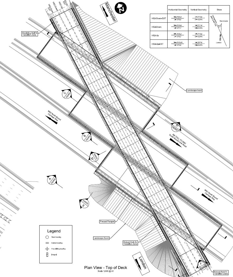
M42 Coleshill Box Structure carries four HS2 tracks over the existing M42 and M6 Toll, and M6E to M42S link connector road at an approximate chainage of 162+600. The design speed of the structure at this location is 360 km/h.
The baseline design of the M42 Coleshill Box Structure consists of a skewed box structure with inverted T beams integrally connected to supporting walls parallel to the M42 roadways.
The angle between the centerline of the tracks and the centerline of the carriageway is 27°, which following the definition provided in Figure 4, means a 63° skew angle. A plan view of the structure is shown in Figure 15.
A section of the structure taken perpendicular to the supporting walls is also provided in Figure 16.

The distance along the track between the skewed deck ends is about 173m, with three skewed spans of approximately similar lengths. The precast concrete beams are orientated perpendicular to the supporting walls to minimise its length and to improve the dynamic structural response to the passage of the trains. The total depth of the deck (precast beam and cast in situ slab) is 2.40m.
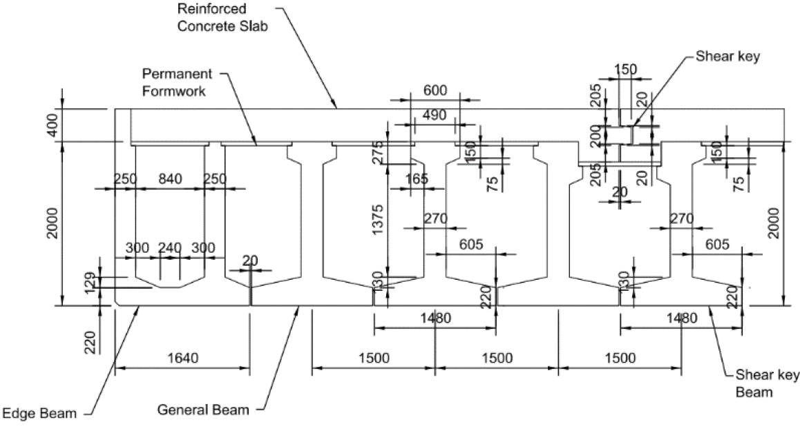
The units are separated by dry vertical joints in the supporting walls, and horizontal dry joints in the deck slab parallel to the inverted T-beam, as shown in Figure 17. The design intent of these joints is to limit the demand in the substructure and foundation resulting from long-term and temperature effects. The addition of shear keys in the joints ensures the continuity of the displacement perpendicular to the plane of the wall or slab at the joint.
The structural deck joints located at each end of the three-box structure is inclined at 63° with the track centerlines. These joints are located between the Coleshill Box structure and the backfills supported by retaining walls are located on either side of the structure.
Design challenges
Originally, the main problem with this structure was localised at the abutments as they were highly skewed. This created two main issues, which became especially relevant for slab track design:
- It was impossible to accommodate the slab track with the current skewed design. As presented in section “Additional constraints posed by the skewed crossings” with the level of skew , it would have been virtually impossible to design slab track able to fit the geometry on the abutments.
- There was excessive differential transversal displacements between the deck and the abutments, which were exacerbated by the high skew angle. Values for this transversal displacement for the baseline design were in the range of 11mm, more than twice the 5mm limit stated by HS2 Ltd even with the use of special fastenings.
Design adaptations
After extensive engagement between HS2 Ltd and the civil contractor, and with support from the precast slab track designer, it was finally possible to mitigate both effects by providing structural expansion joints (EJ) placed orthogonally to the track.
This was achieved by providing a raft transition at both sides of the structure that allowed for slab track while reducing the relative transversal displacement at the abutment to within admissible limits compatible with the capacity of the fastening system.
- Note: capacity has been increased as part of this liaison, with the implementation of special fastenings with higher capacity for transversal displacement (from 1mm per fastening to a maximum of 2.5mm– thus allowing up to 5mm at bridge joint level.)
Other adaptations incorporated to make the design compliant included:
- The removal of horizontal joints in the deck to make it compatible with track requirements.
- The structural configuration was modified to reduce as much substructure lateral stiffness as possible while controlling the lateral displacements at the structural joints. This mitigated the large demand on the substructure generated by the imposed displacements derived from both time-dependent and temperature-related loadings.
- To further decrease the lateral stiffness of the outermost piles on each pile cap, isolating sleeves were introduced for the piles experiencing the highest demand.
- These sleeves artificially increased the piles’ free length, which would have otherwise become overloaded if subjected to the earth pressure from backfill. That is why the backfill behind the walls was removed, eliminating the additional problem of unbalanced pressures in the abutments due to the skew angle.
- Additionally, due to the length of the structure, and to avoid the use of rail expansion joints (RED), which would be a burden on installation and operation, extension of the rail stress limit was granted from 92 MPa to 112 MPa.
- The transition structure consisted of two distinct structures, shown in Figure 18 below, which replace the original backfill:
- A deck sawtooth extension, with a 1.0m deep deck slab integrally connected to the 1.6m deep walls A1/A2 and supported by an array of rectangular columns (1.3m x 1.4m)
- An independent transition structure (raft slab) similarly consisting of a 1.0m deep deck slab supported on an array of individual columns (1.3m x 1.4m) and integrally connected to the transition piers.
- Expansion joints are oriented perpendicular to the track at the transition between the sawtooth deck extension and the transition structure and between the transition structure and the deck of the adjacent viaducts.
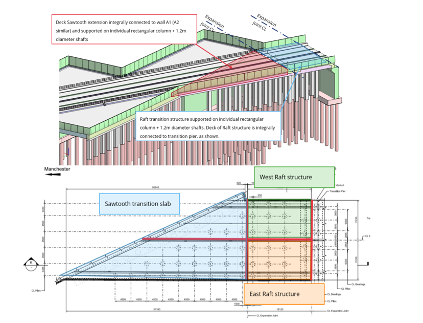
These modifications, implemented during the design stage, led to the complete fulfilment of HS2 requirements and to a much better behaviour of the structure from a track point of view.
M6 Motorway North Viaduct
Baseline design
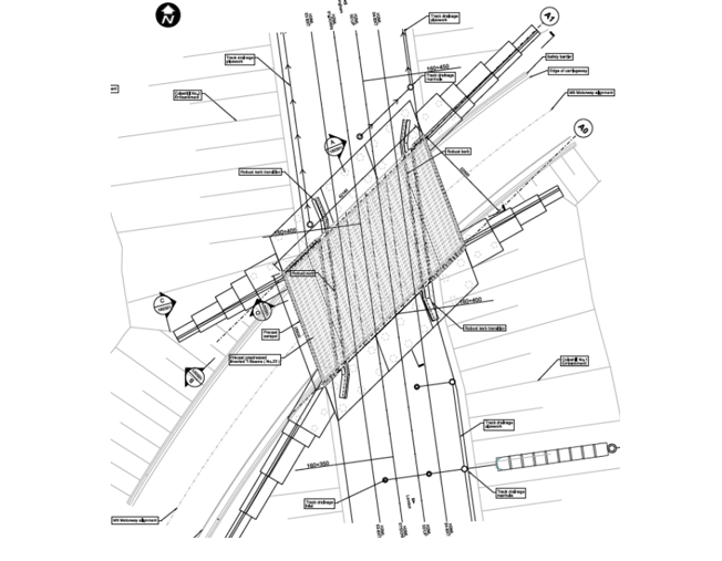
M6 Motorway North Viaduct carries four HS2 tracks over M42N to M6E interchange connector road at an approximate chainage of 160+364 to 160+399, with the design speed of the structure at this location being 360 km/h.
The baseline design of this structure consisted of a single-span portal, fully integral structure, with inverted T precast prestressed concrete beams and in-situ reinforced concrete slab.
The angle between the centerline of the tracks and the centerline of the carriageway is 58°, which following the definition provided in Figure 4, means a 32° skew angle. A plan view of the structure is shown in Figure 19.
Design challenges
As before, originally the main problem with this structure was localised at the abutments, as they were highly skewed. This created the two same main issues already presented for the M42 Coleshill Box Structure, which became especially relevant for the slab track design.
On top of that, the baseline design didn’t comply with the following requirements:
- The transversal displacements at both abutments exceeded the limit of 5mm under SLS Characteristic (in the range of 6mm).
- There were transverse joints splitting the structure into three segments which intersect with the track, and these were not perpendicular to the track slab.
- The deck ends at abutments were not perpendicular in relation to the track.
Design adaptations
In another collaborative exercise between HS2 Ltd and the civil contractor, and with the support of the precast slab track designer, it was finally possible to comply with the requirements by implementing some adaptations to the original design without changing the nature of the structure.
A summary of these main changes included:
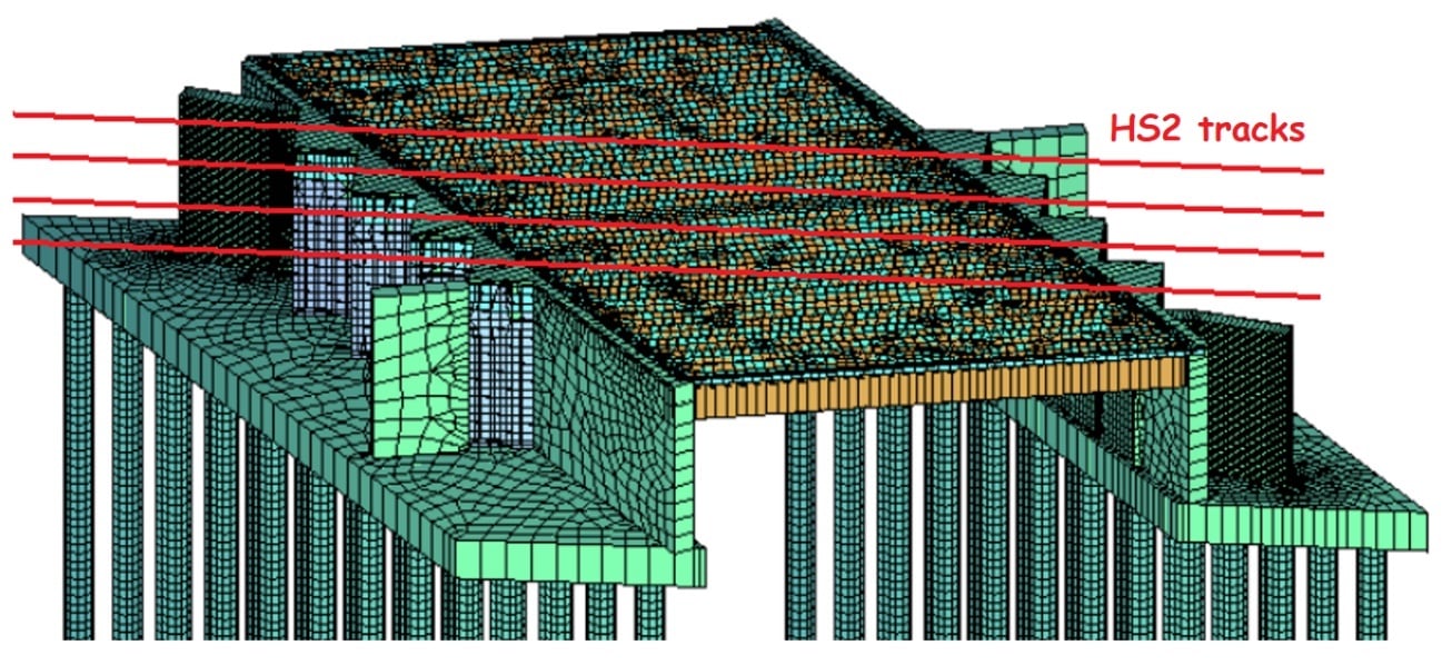
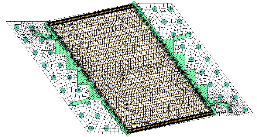
- Four reinforced concrete wedges being added to each abutment. Each wedge is perpendicular to one HS2 track and will be rigidly connected with the abutment walls.
- All transverse joints between segments are removed and the structure is to be designed as one segment.
- Inverted T beams are proposed to be 2m deep whereas the slab thickness is proposed to be 300mm thick (min.)
- The voids between the beams can be filled in proximity of both abutments to create wider diaphragms to provide greater deck stiffness at both abutments if required.
- The pilecaps are extended towards both embankments and, in consequence, the wingwalls need to be slightly rearranged to fit into the new pilecaps’ geometry.
M42 Maston Box Structure
Baseline design
The proposed M42 Marston Box structure carries two HS2 tracks over the existing M42 motorway at an approximate chainage of 167+550. In this case, the design speed of the structure was 360 km/h.
The M42 Marston Box Structure was originally designed with skewed abutments in order to suit the geometry of the obstacle crossed and to minimise the structural depth as square spans would inevitably be longer and not viable considering constraints at that time.
M42 Marson Box is an integral two-span skew bridge around 82m long as shown in the Figure 23. Its main axis is parallel with HS2 tracks but expansion and contraction from temperature changes might generate a twisting effect that would create lateral movement with respect to the tracks at the abutments. It is also worth noting that the skew angle in this case is about 61 degrees.

Design challenges
This design presented a double cell box structure over the M42 Motorway. The main challenge of this proposal was located at the interface between the structure and the abutments due to the differential relative movements between the two.
Design adaptations
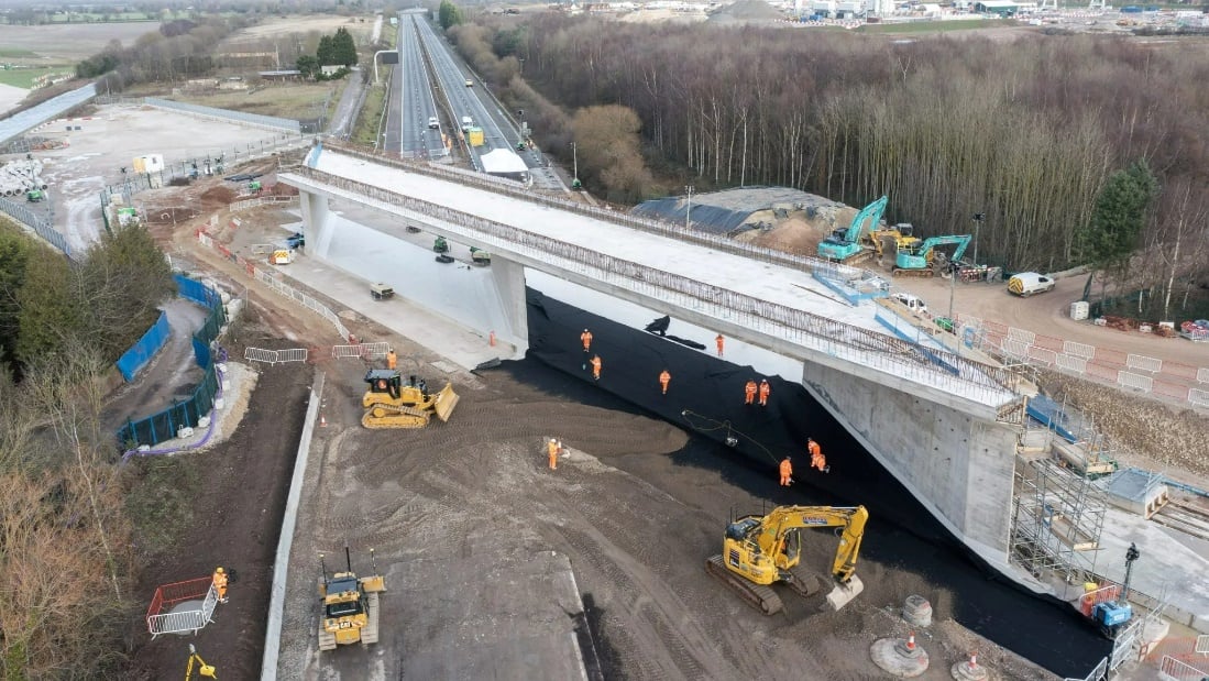
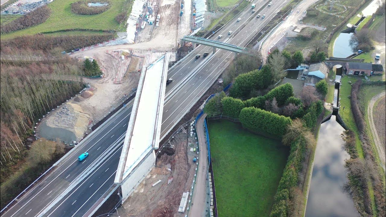
In this case, the alternative solution developed by the civil designers to fulfil the HS2 requirements led to a semi-integral structure with three central skewed walls acting as piers with an extension each side, which are monolithically connected to the main structure and supported on bearings on the abutments, see following images. The functional cross section of the added side spans is similar to the original design.
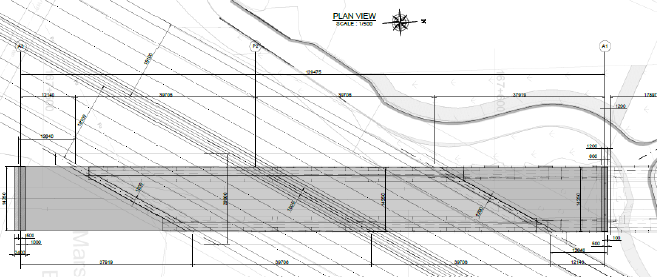
This alternative solution creates a non-skewed abutment with guided bearings that reduce the transversal displacements. These additional side spans and abutments minimise the earth pressures on the skewed abutments.
This was selected as the preferred solution after a consultation process with HS2 Ltd. It provides the following advantages compared to the baseline solution:
- Faster construction process, reducing the need for prolongated night shifts. Reduced disruption to motorway users as the box is constructed offline and pushed into place during a seven-day closure of the motorway.
- Cost reduction.
- Construction health and safety risks reduction as construction of the box structure is undertaken offline and motorway works only take place during full closure.
- Less visual impact.
- Significant reduction in materials and hence, embodied carbon, compared with the baseline design.
- Meets the adjusted HS2 lateral displacement requirements for skew structures.
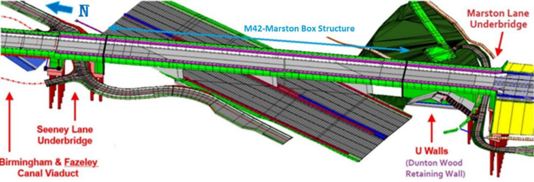
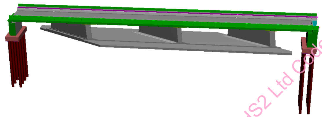
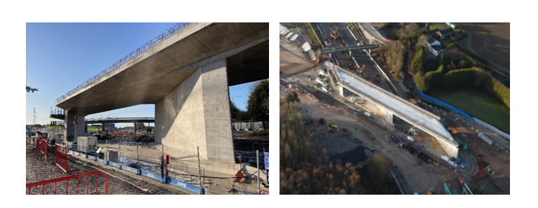
Figure 28 – M42 Marston Box. Alternative design: construction (1)
Chattle Hill Box Structure
Baseline design
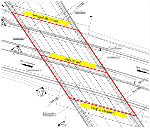
Chattle Hill Box Structure carries 4 HS2 tracks over the A446 Lichfield Road at chainage of 164+035. The original structure is a reinforced concrete portal frame (cast in-situ) supported on pile foundations. Once again, the design speed of the structure is 360 km/h.
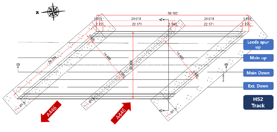
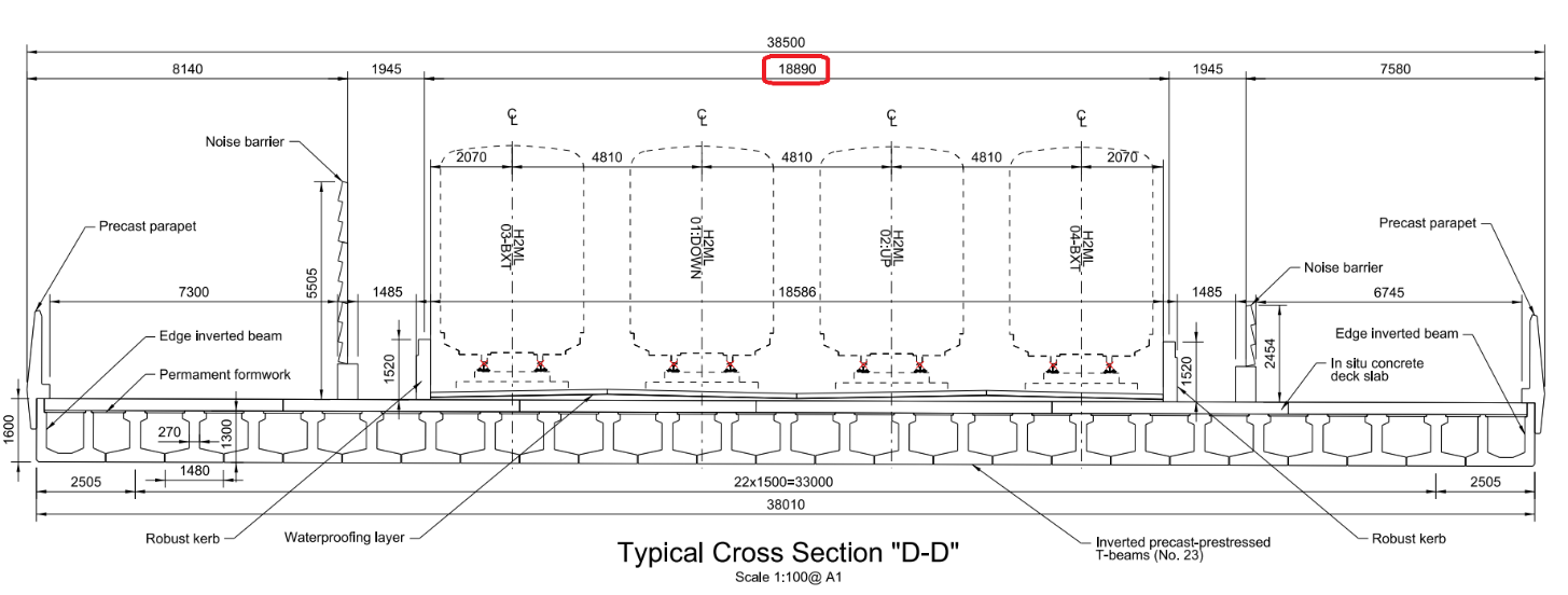
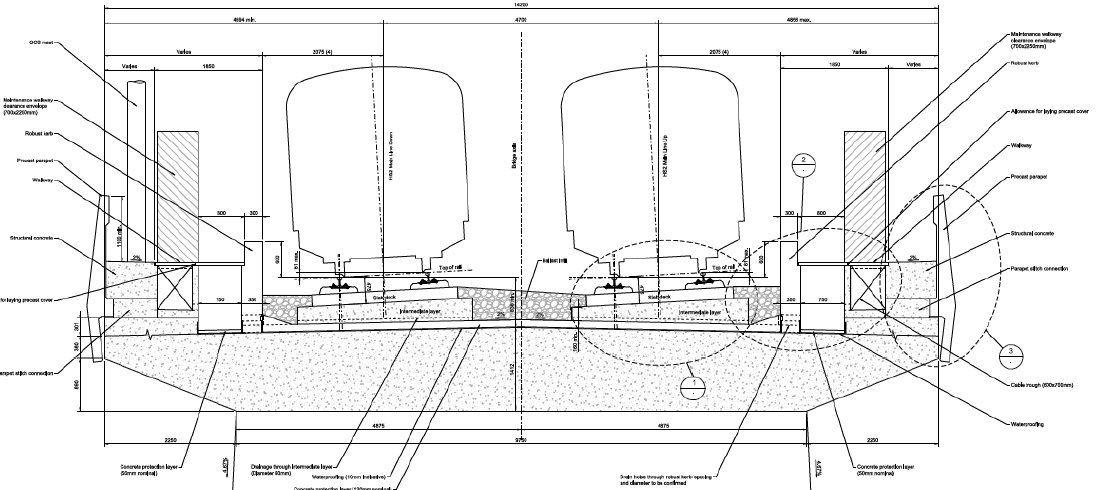
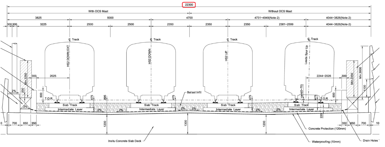
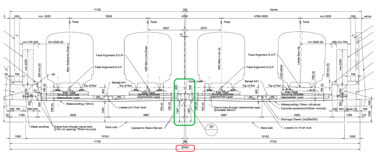
The skew angle, following the definition provided in Figure 4, is 50°. What makes this structure unique, apart from the high angle of skew, is that the bridge supports 4 tracks, with a total width of about 22m as shown in the cross section below.
Design challenges
The major implication of such a wide deck relates to the differential displacements between the deck and the abutments. In this case, considering the centre of the deck as the fix point with regards to the transversal displacement due to temperature variations and creep and shrinkage, there is 8m between this point and the external rails. A rough estimation of the displacement of the outer rails with respect to the centre of the bridges shows values far exceeding the initial +/-1mm limit requested by HS2 Ltd.
On top of that, the baseline design didn’t comply with the following key requirements:
- The angle between the track and the structural joint at abutment exceeded the maximum 30° skew angle limitation.
- The transverse differential displacements at both abutments exceeded the limit of 5mm under SLS Characteristic.
Design adaptations
To fulfil HS2’s requirements, the alternative solution developed by the civil designers meant modifications to both the structure and substructure. The main adaptations undertaken to make the design compliant are summarised below.
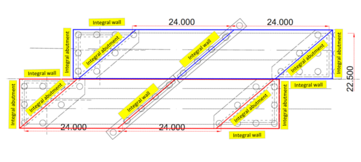
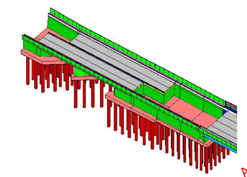
- Split the deck into two: as shown in Figure 35. By doing this, the effect of a very wide deck on the outer tracks does not affect the structure anymore.
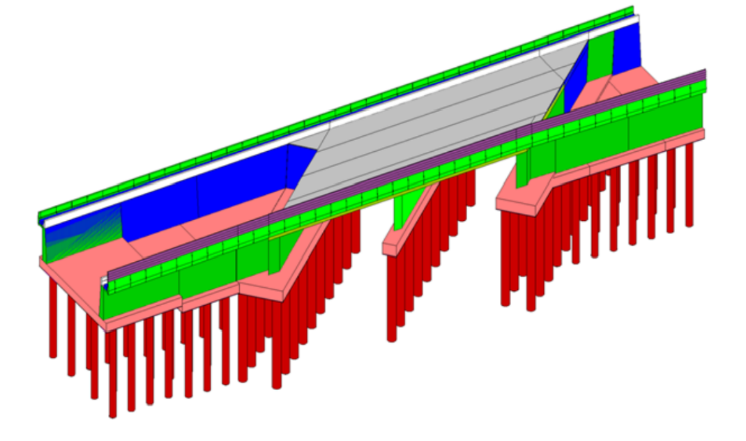
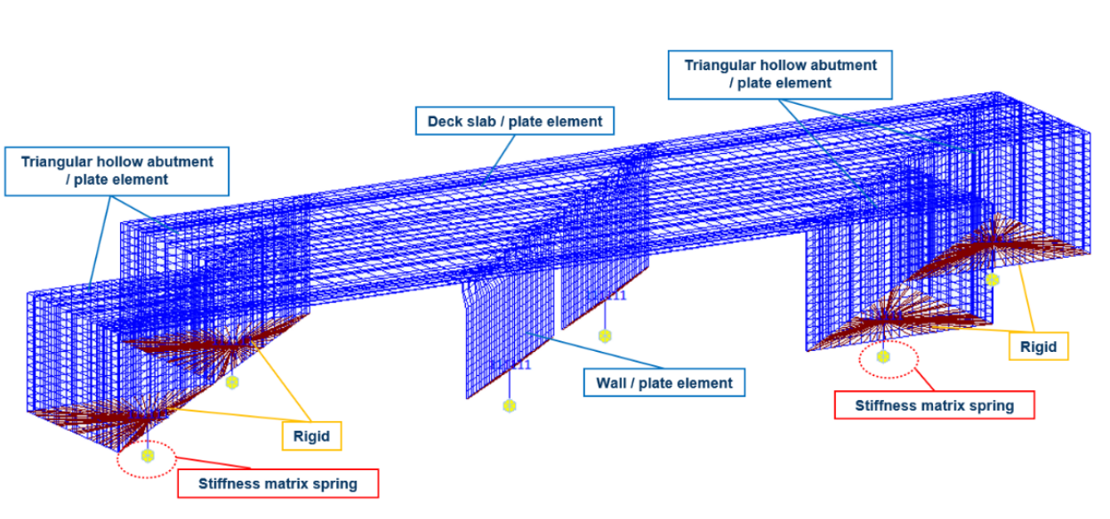
- Elimination of the skewed interface between the structure and the abutment: different options were considered. the selected solution presents a full integral concept in all the supports, including a triangular hollow-box extension in each of the abutments. As shown in the images below, this guarantees independent behaviour of the two sub-structures and a non-skewed transition at the abutments. Rail stresses are kept under control without the need of increasing the allowable limit.
Conclusion
As HS2 designers are currently proposing integral solutions for structures with features beyond the recommended limitations provided by the different codes, it becomes essential to enlarge the knowledge of the interaction between structure, abutment, and subsoil to enable the design verifications according to Eurocode requirements, as this interaction usually influences the behaviour and design of the integral structure.
For the HS2 project, early engagement with the slab track designer at civil design stage has been fundamental in minimising the redesign of structures where skewed geometry at abutments imposed unbearable constraints to the design of the slab track system.
This engagement allowed mitigation measures to be agreed in both civil and track domains: in civil design, by providing non-skewed transition at the abutments and minimising the transversal displacements between structures and adjacent earthworks sections; and in track design, by allowing the use of special fastenings with enhanced capability to withstand transversal displacements of the rail, which at the same time required an adjustment of limits by HS2 Ltd.
The combination of mitigation measures and requirement tailoring would have not been possible without a comprehensive analysis of the applicable standards for civil structure and track design in the UK and other countries (especially in Germany where resides most experience in slab track systems for high-speed lines in Europe).
Acknowledgements
- Main Work Civil Contractor: BBV
- Precast Slab Track Supplier: PORR AG and its design house for this project Vienna Consulting Engineers ZT GmbH VCE
References
Research papers
- Braun, Anton et al. (2006). “Frame structures in bridge construction. Design, analysis, and economic considerations”. International Workshop on the Bridges with Integral Abutments.
- C Iles, David. (2006). “Integral bridges in the UK”. International Workshop on the Bridges with Integral Abutments.
- Moustafa, Al-Ani et al. “Criteria and Guidance for the design of Integral Bridges”.
- Rui-Wamba, Javier. (2004). “Puentes integrales y semi-integrales de ferrocarril”. Revista de Obras Públicas.
- Rui-Wamba, Javier et al (2011). “A Spanish Perspective on Integral High-Speed Railway Viaducts”
- Stastny, Alexander (2021). “Neue Richtlinie zur (semi-)integralen Bauweise von Eisenbahnbrücken (New guideline for the (semi-)integral construction of railway bridges)”. Konstruktiver Ingenieurbau.
- “Modified Geometry of Transition Slabs for Integral Bridges”. Damien Dreier Structural Concrete Laboratory (IBETON), Ecole Polytechnique Fédérale de Lausanne (EPFL), CH 1015 Lausanne.
- Aksil, Salem; Durand, Paul-Emile. “Influence of Uniform Thermal Cycles in Reducing the Rail Stresses Induced by Creep and Shrinkage Built over Time in Concrete Railway Bridges”. Systra International Bridge Technologies.
Codes and Standards
- PD CEN/TR 17231:2018 (Eurocode 1: Actions on Structures – Traffic Loads on Bridges – Track-Bridge Interaction)
- BS EN 1991-2:2003 Eurocode 1: Actions on structures – Part 2: Traffic loads on bridges
- Ril 804 series “Eisenbhanbrücken (und sonstige Ingenieurbauwerke) planen, bauen und instand halten”
List of notations
DRMB Design Manual for Roads and Bridges
EJ Expansion joint (structural)
HS2 High Speed Two Ltd
RSI Rail Structure Interaction
RED Rail Expansion Device
SLS Serviceability Limit State
ULS Ultimate Limit State
Footnotes
- Please note that cl. 8.2.1 of CD 350 The Design of Highway Structures allows bridges with a skew angle greater than 30 degrees or lengths greater than 60 m to be designed as integral structures.
- Fully integral structure: integral bridge where the superstructure and substructure area designed to move together to accommodate the required translations and rotations (monolithic structure).
- Semi-integral structure: integral bridge which has bearings at the abutment and/or piers and, as a result, the superstructure and substructure do not necessarily have to move together to accommodate the required translations and rotations.
- Image from “Modified Geometry of Transition Slabs for Integral Bridges Damien Dreier Structural Concrete Laboratory (IBETON), Ecole Polytechnique Fédérale de Lausanne (EPFL), CH 1015 Lausanne”.
- Englesmann, S; Slaich, J; Schafer, K. “Conceptual and structural design of integral concrete bridges”. DAfStB Heft 496.
- Figure adapted from Stastny, Alexander (2021). “Neue Richtlinie zur (semi-)integralen Bauweise von Eisenbahnbrücken (New guideline for the (semi-)integral construction of railway bridges)”. Konstruktiver Ingenieurbau. For structures within the AK1 range, sufficient experience is available, and the deformations magnitudes are safe. For integral structures above this level, additional requirements shall be verified with regards to track twist and compatibility with the backfill area.
- Figure adapted from “Puentes. Apuntes para su diseno, calculo y construccion”. Javier Manterola.
- Many factors influence the effect of creep and shrinkage on the response of concrete members in integral bridges. Factors influencing concrete shrinkage include water-cement ratio, water content, workability, type, and content of aggregate and relative humidity. A positive correlation has been observed between concrete shrinkage and water-cement ration, while a negative correlation has been observed for aggregate content, relative humidity, and aggregate-cement ratio. Factors that affect concrete creep include sustained stress, concrete strength, type, size and content of aggregate, water-cement ratio, slump, air content, loading age, relative humidity, volume surface ratio and temperature. A positive correlation has been observed between creep in concrete and slump, temperature, and sustained stresses, while a negative correlation has been observed for aggregate content, relative humidity, concrete strength, volume-to-surface ratio, and loading age.
- Salem Aksil, I; Durand, Paul-Emile. “Influence of Uniform Thermal Cycles in Reducing the Rail Stresses Induced by Creep and Shrinkage Built over Time in Concrete Railway Bridges”. Systra International Bridge Technologies.
- Figure adapted from Stastny, Alexander (2021). “Neue Richtlinie zur (semi-)integralen Bauweise von Eisenbahnbrücken (New guideline for the (semi-)integral construction of railway bridges)”. Konstruktiver Ingenieurbau.
- EnkaDrain® product proposed for its use in abutments
- This approach is proposed for the next revision of EN 1991-2:2003, 6.5.4 as stated in Annex E of PD CEN/TR 17231:2018 (Eurocode 1: Actions on Structures – Traffic Loads on Bridges – Track-Bridge Interaction).


