Managing uncertainty in ground conditions in design on a megaproject where ground investigation is highly variable
Ground conditions present one of the major areas of uncertainty and risk for High Speed Two (HS2) Phase One and have a significant impact on project affordability.
The ability to effectively and appropriately manage ground risk in design in a consistent manner is complicated by the varying degrees of completeness of ground investigation which may vary from asset to asset and in some areas may be limited. Designers must make best use of the data so to reflect the most likely prevailing ground conditions however, due consideration to potential variations considering gaps in data also needs to be given.
This paper documents the risk-based approach taken in scheme design (including coordinated design, spatial arrangements, approval in principal documents and detail to assist in development of a target price) of Contract N1 & N2 (Area North) where local and regional scale reviews of data were undertaken for different ground conditions encountered, and a qualitative ground investigation classification scheme created (GI Class 1-5).
This classification scheme enabled a common understanding of the gaps in information across N1 & N2 the contract from asset to asset while also serving as a reference to define ground models and parameters in a consistent way making use of regional data sets with appropriate factors to reflect the level and extent of GI available where limitations existed. This enabled geotechnical designers across the globe to reduce the potential for overly cautious costly designs and optimise the design while giving due consideration to geotechnical risk.
Examples of the approach are presented for different classes showing the evolution of the design and risk profile as new data became available.
- Written by
-
Imran Farooq (BBV/Mott MacDonald)

-
Antony Drake (BBV/Mott MacDonald)

-
Christopher Brook (Mott MacDonald/BBV)

- Resource type
- Resource type: Technical Paper
- Intended audience
- Contractors
- Tags
- geotechnical posts
- ground investigation posts
- Risk Management posts
Introduction
The authors were part of the team responsible for geotechnical design on the northern section of High Speed Two (HS2) Phase One – Lots N1 and N2 (Area North). Area North includes Long Itchington Wood Green Tunnel to Delta Junction and Birmingham Spur and the Delta Junction to the West Coast Main Line (WCML) tie-in and are the responsibility of the BBV Integrated Project Team.
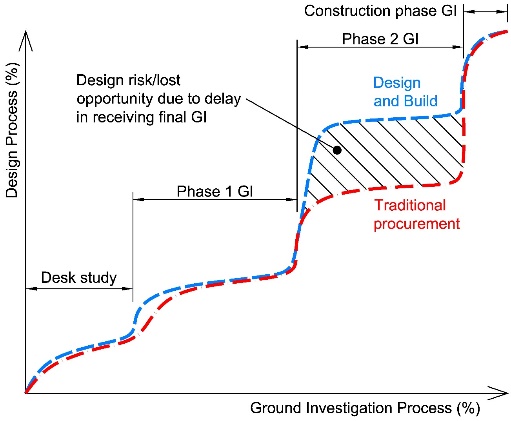
Ground conditions present one of the major areas of uncertainty and risk for HS2 Phase One and have a significant impact on project affordability. As is the case for many projects, there were areas where the optimum quantity, type or quality of information was not available at the start of scheme and detailed design. As a design and build type contract the design may be required to progress concurrently with ground investigation, such that there may be some gaps in available ground investigation information at the start of design. However, this should be viewed in the context of the other important factors for a project – cost, programme, construction sequence, practicality which may require a design with risk suitably highlighted, understood and managed. Figure 1 presents a schematic of the progress of ground investigations relative to the progress of the design on the different contract types.
Contractors and designers need to manage the design ground risks in a professional manner, as they feed directly into the main project risks – time, money and safety. By having an agreed approach to managing the risk associated with limited information, conflicts, contractual issues and claims can be reduced, allowing projects to run as smoothly as possible. Design can also be optimised for the information available at the time in a clear and risk-controlled manner.
On small projects, it may be relatively simple to comprehend, communicate and record ground risks and associated design decisions. It may be possible to communicate verbally within a small team, maintain good relationships with all parties, and record via a risk register. On small projects, the ground investigation information shortfall can sometimes be made up with engineering judgement, local knowledge or safe assumptions.
On large projects or contracts, such as HS2 Area North, with multiple assets and design and construction teams spread across the world, a systematic approach using a standardised framework is required.
On large projects, such as HS2 N1 & N2, with multiple assets and design and construction teams spread across the world, a systematic approach using a standardised framework was required.
The ability to effectively and appropriately manage ground risk in design in a consistent manner across N1 & N2 was complicated by the varying degrees of completeness of ground investigation which may vary from asset to asset and in some areas may be completely absent. Designers must make best use of the data to reflect the most likely prevailing ground conditions, however, due consideration to potential variations considering gaps in data also needs to be given.
Ground investigation and design for HS2 has been carried out in a phased manner as presented in Table 1.
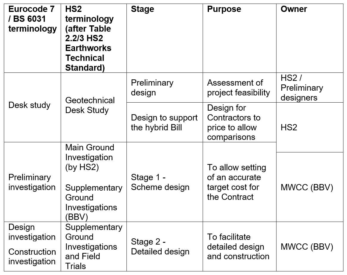
HS2 Ltd designed, commissioned and carried out the main ground investigation prior to awarding the Main Works Civils Contracts to the design and build contractors. However, the information could not be completely delivered prior to award and therefore design was required to be carried out on some assets with little or no intrusive ground investigation.
To manage this risk, a ground investigation (GI) classification scheme for assets was developed to enable the design team to consistently record the information available for design of assets at various stages, follow a consistent approach to design based on the amount of information available and to communicate the available information status to all design disciplines and management teams in a simple manner.
Scheme design ground investigation classification
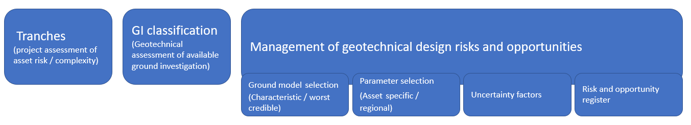
The GI classification was developed early in Scheme design (Stage 1) to allow designers to consistently record the information available for design of assets and follow a consistent approach to design based on the amount of information available. The approach was based on several processes summarised in Figure 2.
Tranches
Due to the scale of Area North the assets were sub-divided into different ‘tranches’ by the project team based on programme, impact on environment and consents (in terms of planning applications etc.), design complexity, construction complexity and aesthetical impact. Since this assessment didn’t have a significant geotechnical input, assets were subsequently assessed for an initial understanding of geotechnical risk and a further tranche by the geotechnical team was added:
- Tranche 1 – High-risk/Complex Assets
- Tranche 2 – Potential High Saving Assets
- Tranche 3 – Non-complex/Exemplar Assets
- Geotechnical High Risk ~Tranche 4 (tranche terminology not used) – earthworks assets with certain height/depth, complex geology/groundwater and/or significant geo-hazard identified
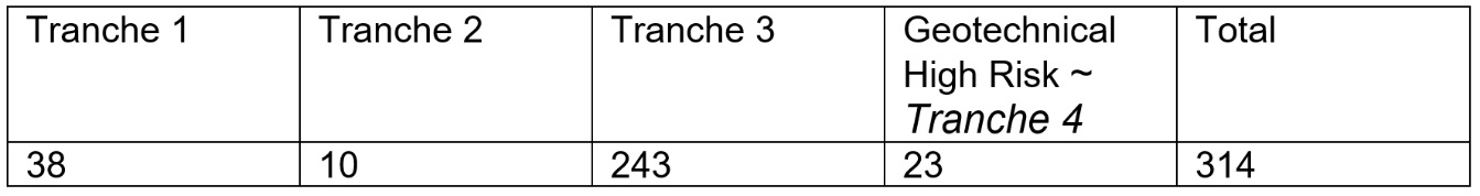
Out of 314 main assets at scheme design stage the breakdown of tranche categories determined in Stage 1 is summarised in Table 2.
GI classification
Early in Stage 1 there were assets with different project risk categories (tranches) and design was required to commence where some of these assets had lots of ground investigation and some had none at all. A method was required to provide a common understanding of the availability of information for each asset, to enable communication of this and the associated risk to the wider design team, along with a process of managing that risk and also to communicate the risk to the contractor trying to set a target price.
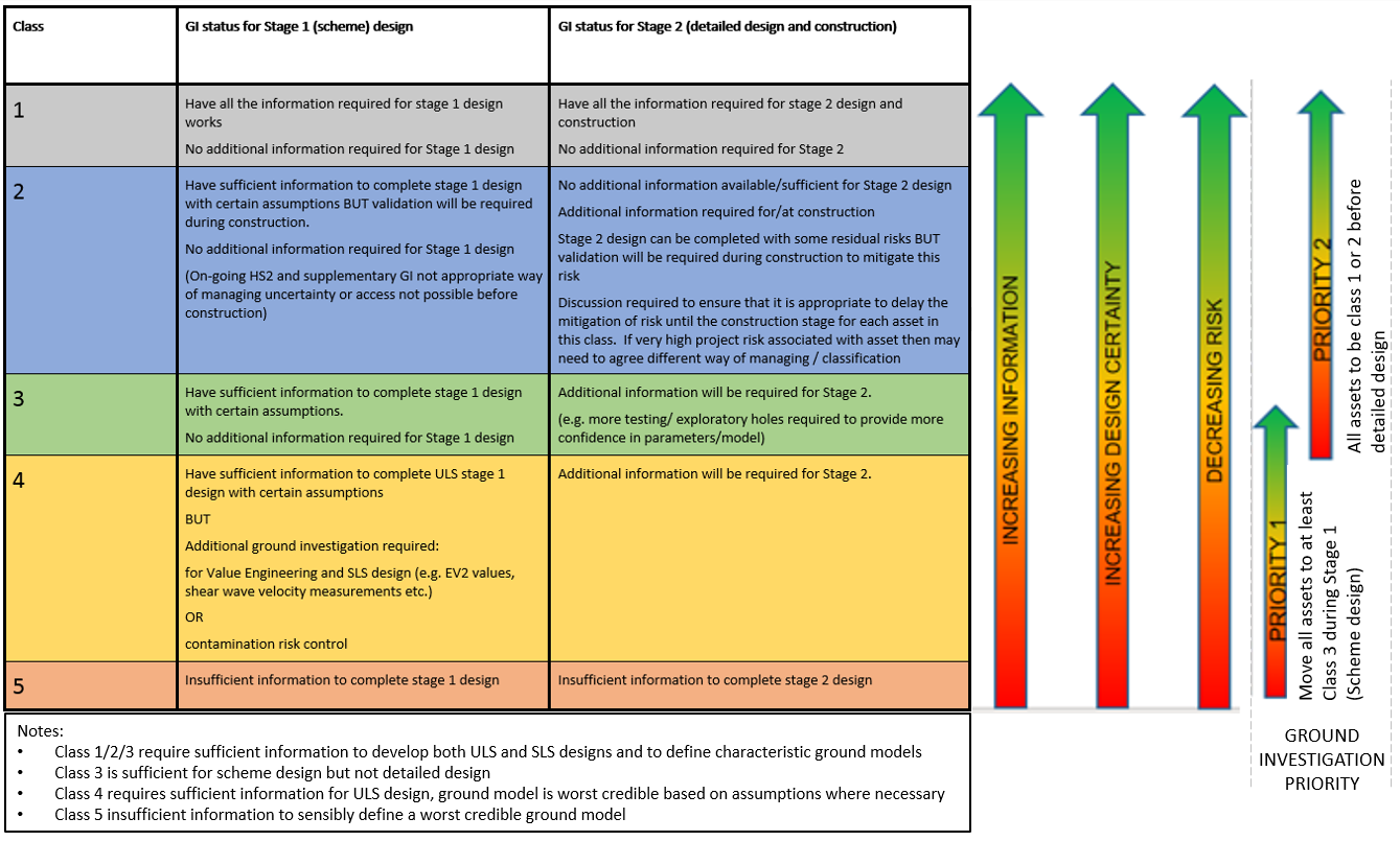
A five-stage GI classification scheme was developed. The scheme went from situations where there was none or very little information, called Class 5, up to where there is considered enough information to do detailed design and to construct.
A summary of the GI classification scheme developed is presented as Figure 3.
Standardised guidance was developed based on:
- ground profile and geological structure;
- groundwater characteristics;
- soil and groundwater chemistry;
- contamination potential;
- index properties;
- strength and stiffness profiles;
- rock strength and deformability;
- rockmass properties;
- earthworks and selected fill suitability.
Guidance was also provided on which topics are applicable to which assets (e.g. cutting, embankment, tunnel etc) for which materials the assessment is relevant for and whether the particular item was required/options/required with statistically high certainty or whether lower certainty was acceptable (e.g. for class 4).
It is noted that where the classification, summarised in Figure 3, states insufficient information to complete design, this is to highlight the level of uncertainty that would be associated with a design specific to the asset location. Design for the assets in this category could be carried out using relevant methods to manage the risk and opportunity using the wider data body.
The classification is also useful to consider in relation to the project stages. Class 3 is considered to have sufficient information to complete scheme design to a sufficient level to allow an appropriate target cost to be set. This allows prioritisation of GI for assets that are initially GI class 4 and 5 to obtain information to allow them to become GI class 3 or better.
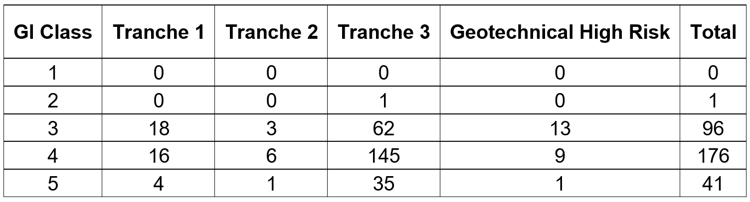
For context, early in scheme design the 314 main assets in the N1 and N2 contract areas were divided into the tranches and GI classes presented in Table 3. 41 assets had a GI class of ‘5’ indicating no or very limited information was available, allowing a focusing of the ground investigation programme towards these assets and where possible delaying the design. Table 4 provides the class at the end of scheme design and shows a progressive improvement of the classes.
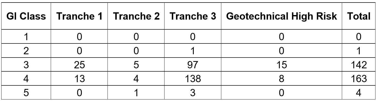
Note to Table 4: four assets have been removed since the April 2018 assessment owing to combining of assets or change in scope.
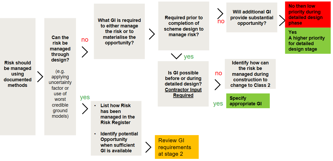
Management of geotechnical risks and opportunities using the GI class
Based on the GI class and tranches, the design approach varies to help manage the risks following the process shown in Table 5 and Figure 4. The approach relies on a geotechnical risk and opportunity register being used appropriately. Risks are present using all approaches – worst credible models and uncertainty factors reduce the likelihood of most of the risk. Conversely, the potential opportunities for design optimisation and reduction in costs put aside to cover risks will in many cases increase in likelihood when using worst credible models and uncertainty factors. The cost associated with these risks has been included within the scheme design presented and there is often an opportunity to reduce the costs associated with the design should additional information be made available.
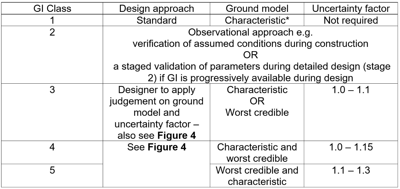
Notes to Table 5: * It is noted in layered soils, a ‘worst credible’ stratification may be appropriate, for example in the case of pile design in glacial deposits.
The ground model comprises the ground profile and/or the geotechnical parameters of the materials under consideration. A characteristic ground model is determined in accordance with Eurocode 7. Worst credible ground profiles consider the reasonable poorest stratification affecting the limit state based on information available. Worst credible parameters are typically close to a lower or upper bound of the available data depending on the limit state (i.e. what is considered lower or upper credible limits). Also see section on parameters derived from regional data sets.
The uncertainty factor was applied in addition to what is required by the design codes and HS2 specification to characteristic parameters. The range in the table above is provided for guidance. Selection of uncertainty factor was carried out based on level of geotechnical risk and ground investigation information available for design.
Several different design approaches were used depending on the certainty in ground and groundwater conditions.
For example, for Class 1 assets where sufficient information was available to meet standards and specifications, design was carried out based on characteristic parameters and conditions for all tranches of assets with relatively low risk transferred to construction stage.
For a Class 4 or 5 asset, the first step was to consider if it was possible to manage the ground risks through design? For example by applying uncertainty factors or using a worst credible ground model.
For some tranche 3 lower risk assets which have no ground investigation information, or for some tranche 1 or 2 assets that were Class 4 where appropriate engineering judgement could be made for the missing information, it was appropriate to follow this path. The approach taken was then documented in the risk register and this also highlighted potential opportunities once additional information becomes available.
If it was considered the risk associated with a lack of information cannot be sensibly managed through design, which may particularly occur for tranche 1 high risk assets, additional investigation works was prioritised. If there was a GI programme risk then there was a broader discussion with the client in how we can manage that risk and a design with significant assumptions requiring verification is produced.
For certain Tranche 2 assets a parametric assessment to establish upper bound and lower bound solutions was considered. The cautious solution was used as the baseline solution and the optimistic solution was only used to identify potential opportunities.
Parameters derived from regional data sets
Where no or very limited geotechnical testing of materials had been carried out (GI class 4 and 5 assets), design was still often required to proceed. To this end, ‘regional’ parameters were derived based on all the data for particular materials available across the N1 & N2 contract areas.
At scheme design, the regional parameters derived included assessed characteristic and worst credible values for various parameters. The characteristic values and range of data were particularly valuable to allow comparison in situations where relatively limited asset specific information was available, to allow either more confidence in using characteristic values or to support a change to use of a worst credible ground model. The worst credible values derived from the regional data enabled design to progress in areas with limited GI with an appropriate degree of caution given the stage of the project.
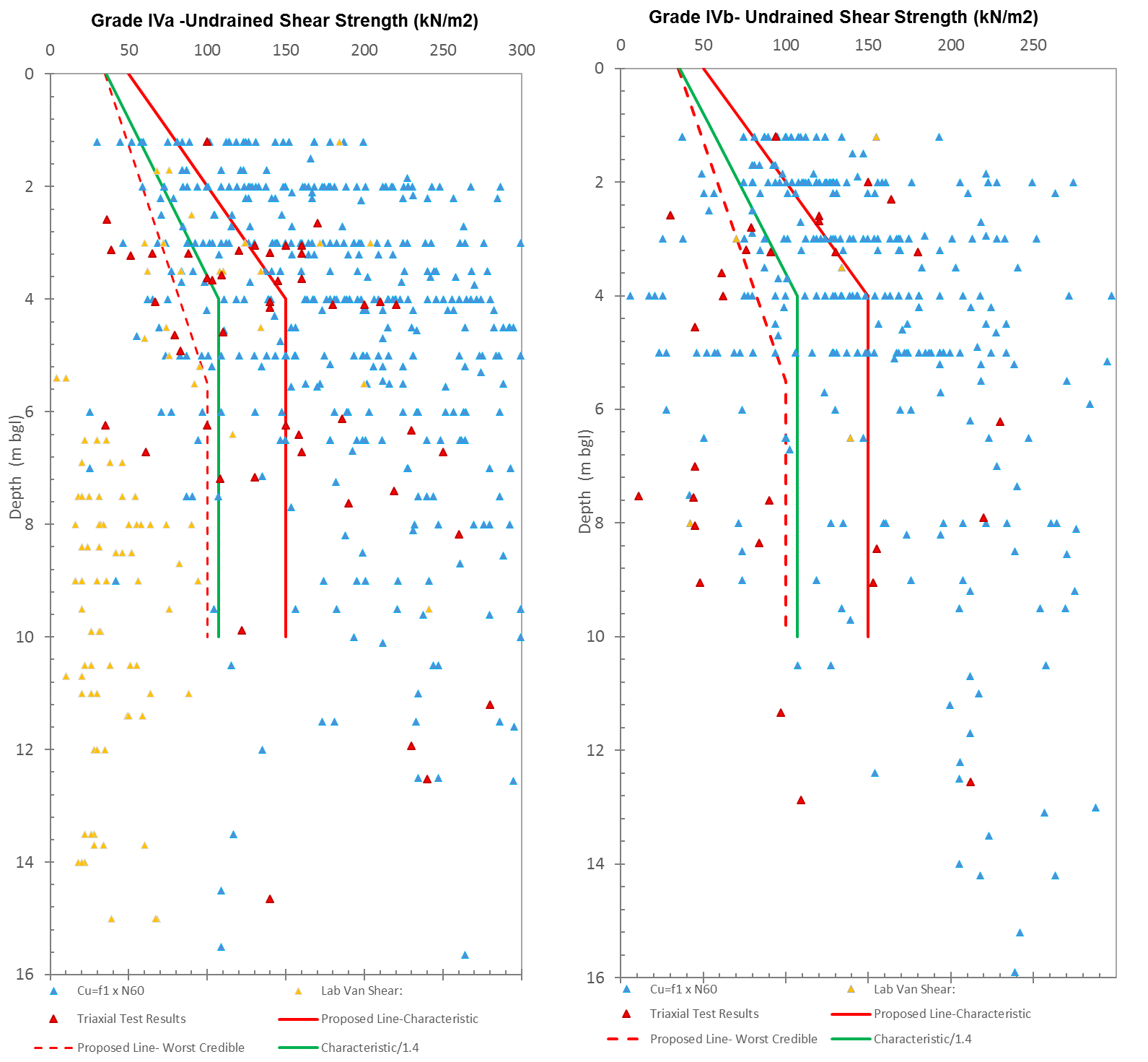
An example of the difference between characteristic parameters, factored characteristic and worst credible parameters for the undrained shear strength of grade IV Mercia mudstone (following CIRIA C570 simplified weathering scheme for Mercia mudstone[2]) is presented in Figure 5. The graphs assume a lower value is critical.
It is noted that the worst credible values are typically lower than a factored characteristic. This is important as in some scenarios worst credible parameters may not be factored.
It is also noted that it is possible to have parameters that are worse than the worse credible values selected. However, these situations are considered likely to be rare and be identified as data becomes available. Depending on the failure mechanism it must be considered whether low parameters restricted to particularly zones or horizons will govern.
Example
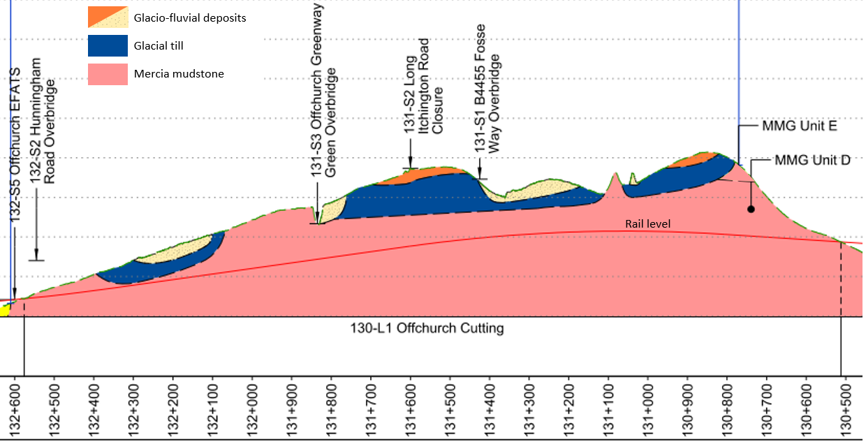
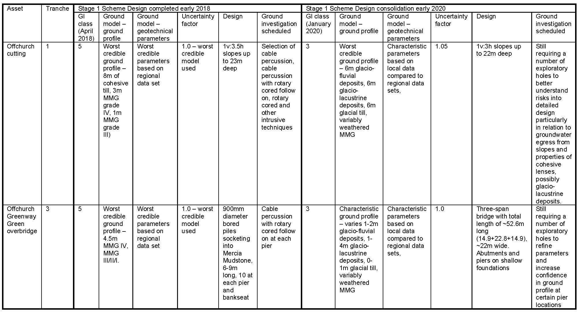
An example of the GI classification in practice is presented using Offchurch Cutting and Offchurch Greenway Green Overbridge. Offchurch Cutting is a 2.1km long cutting with a maximum depth of around 23m, located near Offchurch approximately 4km east of Royal Leamington Spa. At Stage 1 scheme design, no ground investigation had been completed in the area owing to land access issues. The asset was assigned a GI class of ‘5’ and Scheme design was required to proceed using desk study information. A reproduction on the geological interpretation at desk study stage is presented in Figure 6.
As the project proceeded through scheme design stage, a reduction of the target cost was sought and so assets were redesigned using ground investigation data that had become available. In the area of Offchurch cutting a significant amount of ground investigation data had been completed as presented on Figure 7. This led to the GI class improving to a ‘3’.
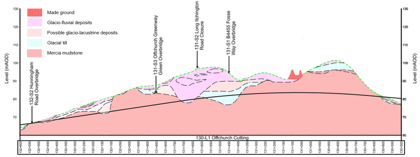
The assets were reclassified and redesigned in several cases, realising the opportunities recognised at scheme design. A summary of the design process and outcomes is presented in Table 6.
Even when using what are thought likely to be worst credible ground models based on the available information, it is possible actual conditions locally, particularly the ground profile, may be poorer as new information could reveal worse conditions locally (e.g. local faulted zones or deeper weathered profiles that may not have been picked up in the limited GI or in the desk study. Presence of deeper weathering channels can be credible but assuming the entire cutting or asset to be within a deeper weather zone would not be considered credible without collaborating evidence). On receipt of the GI in the Offchurch area, interbedded and locally thinly laminated fine to medium sand and very soft slightly sandy silty clay, possibly indicative of a glacio-lacustrine or low energy fluvial environment were identified. However, when combined with worst credible geotechnical parameters, the worst credible ground model with relevant uncertainty factor applied to design has been found to manage risks appropriately in most cases, allowing highlighting of opportunities likely to be achievable if additional information can be provided in time for future design stages.
Benefits and challenges
As a means of communicating the amount of information available to management teams from several organisations the classification proved valuable, allowing sensible explanation of the amount of information and focussing of attention. However, there were some challenges ensuring the understanding of the methodology and application by the design teams.
Key challenges included:
- Communication – the process is quite complicated to understand, particularly if it’s not your area of interest, thus it can be quite hard to communicate the value of the process, and following on from that, getting
- Buy-in from all team members takes some effort.
- Consistency in the assessments is also a challenge, especially with lots of different people in different locations working on the project.
- Time is a key challenge – assessing each asset takes time and other parties don’t necessarily appreciate this, and it wasn’t necessarily predicted in the programme or costed.
Notwithstanding the above, the value of the methodology in communicating to the wider team the status of information and how design has proceeded has led to the scheme to be developed for use in detailed design.
Future development and use
The value to the team of the scheme design GI classification has led to the further development of the classification for use in detailed design. At the time of the paper being written detail design was commencing for the first batch of assets and this evolution will be applied at detailed design stage 2.
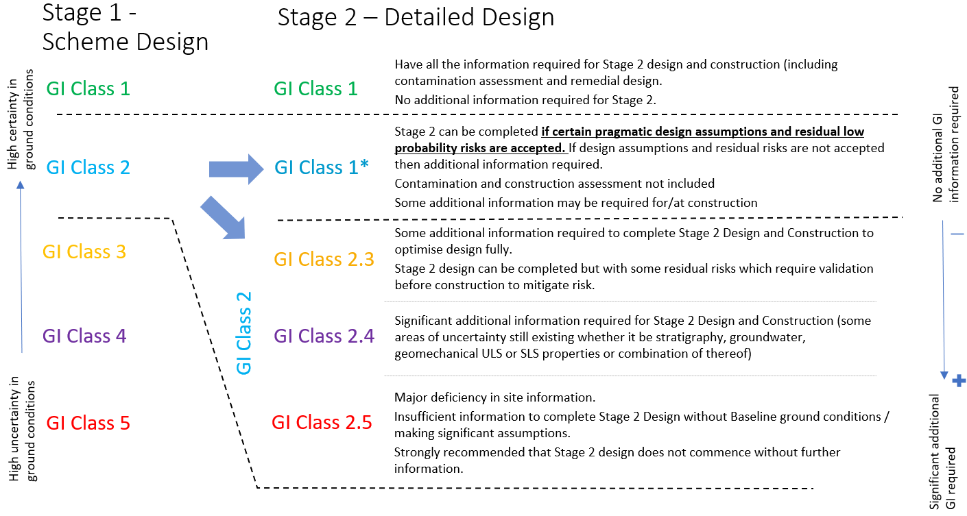
The evolution of the classification is presented in Figure 8.
The detailed design classification recognises the need for design to progress because of the overall construction programme and gives the designer and contractor options and methods to manage if there is a deficiency in site information.
The strategy requires that the following key parameters are defined prior to any design activity being commenced:
Parameter 1 – All assets shall be assigned in to separate tranches and philosophy can vary for different asset tranche similar to scheme design stage, therefore designer should be aware of the tranche for their asset.
Parameter 2 – Assets shall be then classified based on the ‘quality’ of the information available and the certainty in the ground and groundwater conditions as described by the available data (the updated GI classification).
For Detailed Design there are two classes: Class 1 where it is deemed there is sufficient information on the ground conditions or Class 2 where there is insufficient data for detailed design without further qualification.
There is a recognition that the assessment of sufficiency of data may depend on the acceptability of risks arising from the absence of data and/or the assumptions underlining the design. I.e. where robust assumptions are made that manage/mitigate the risk to an acceptable level in this case it may be appropriate to assign Class 1* to denote this (e.g. assuming ground water level to be near ground surface when insufficient monitoring is available).
Class 2 is further subdivided to assess the level of missing information. Given the history of asset classification which evolved during scheme design it is recommended that designers incorporate the scheme design stage classification system as a subscript. That means scheme design Class 3, 4 and 5 that are not able to be upgraded to Class 1 at the start of detailed design, become Class 2.3, 2.4 and 2.5.
Parameter 3 – Where the asset is classified as Class 2, the level of information available for each asset shall be assessed and the design process and methods used vary depending on this assessment. The geotechnical designer shall classify missing information into 4 categories or a combination thereof and assign a sub-script notation accordingly as follows. (The assessment for construction related missing information and contamination related missing information will be carried out by others):
- Missing information impacting SLS only, i.e.in movement only, all other ground risks manageable through design (Designated as m);
- Missing information related to water and or groundwater only, manageable risks on all other aspects of ULS design. (designated W);
- Missing information related to definition of stratigraphy, however strength and other ULS design information is established (designated S);
- Missing information related to establishing strength or other ULS parameter which have direct bearing on ULS design (designated U).
The design process also requires an active risk management strategy and process map which needs to progress as part of the design. A geotechnical risk register should be prepared and will form a critical tool in understanding and communicating the geotechnical risks and uncertainty in ground conditions and groundwater and how it is managed going forward. Where applicable a process map/flowchart (aligning construction programme, design programme, GI programme) should be prepared in conjunction with the Main Works Civils Contractor, to identify key dates and milestones which allow appropriate management of design risks associated with uncertainty in ground and groundwater conditions
Several different design approaches can be used depending on the certainty in ground and groundwater conditions and at what stage ground investigation information will become available. This will need to be assessed on an asset by asset basis.
For Class 1 (and Class 1*) assets where sufficient information is available to meet standards and specifications then design based on characteristic parameters and conditions will be carried out for all tranches of assets with relatively low risk transferred to construction stage. No process map is required further than updating risk registers.
For Class 2.3 or 2.4 assets a process map should be identified as part of the early design activities and agreed with all parties in terms of assumptions, associated risks and proposed mitigation methods. Also, key dates where information is required for design should be specified in the process map. This requires understanding of the GI, design and construction programmes. Furthermore Class 2.3 or 2.4 are assets where some parameters are missing and use of uncertainty factors depending on agreed risk mitigation process map should be considered as a potential risk mitigation measure. The use of this factor and the process map should consider the following:
- The proposed supplementary GI and its scope.
- Stage at which the supplementary GI will be available (a periodic reclassification of the asset should be carried out to re-assess class). Key question to consider Is the GI available at a stage:
- Prior to detailed design, hence is it likely to be class 1 asset before design.
- During detailed design, but in sufficient time to validate assumptions or incorporate changes in the design from additional GI.
- At design completion but prior to construction – hence allowing verification of design (in such case mitigation measures should be identified and agreed to manage the risk as part of the design, if assumptions are not validated, with risks clearly identified
- No further GI – but monitoring during construction hence an observation method can be considered in such case.
The uncertainty factor to be applied is in addition to what is required by the design codes and HS2 specification and use of this should be considered as one of the mitigation measures that can be used in absence of other agreed mitigations. The range in Table 7 is provided for guidance. Selection of the actual uncertainty factor should be carried out based on level of geotechnical risk and ground investigation information available for design. Designer shall also identify in the Geotechnical Design Report (GDR) and risk register what factor is used and its implication on the design. In most cases this factor should be applied to resistance in the design, however in some cases it can be used on the action used in the design (e.g. factoring the K* pressure (force) for in-situ soils behind integral bridges that may influence the ratcheting effects on the bridge structure).
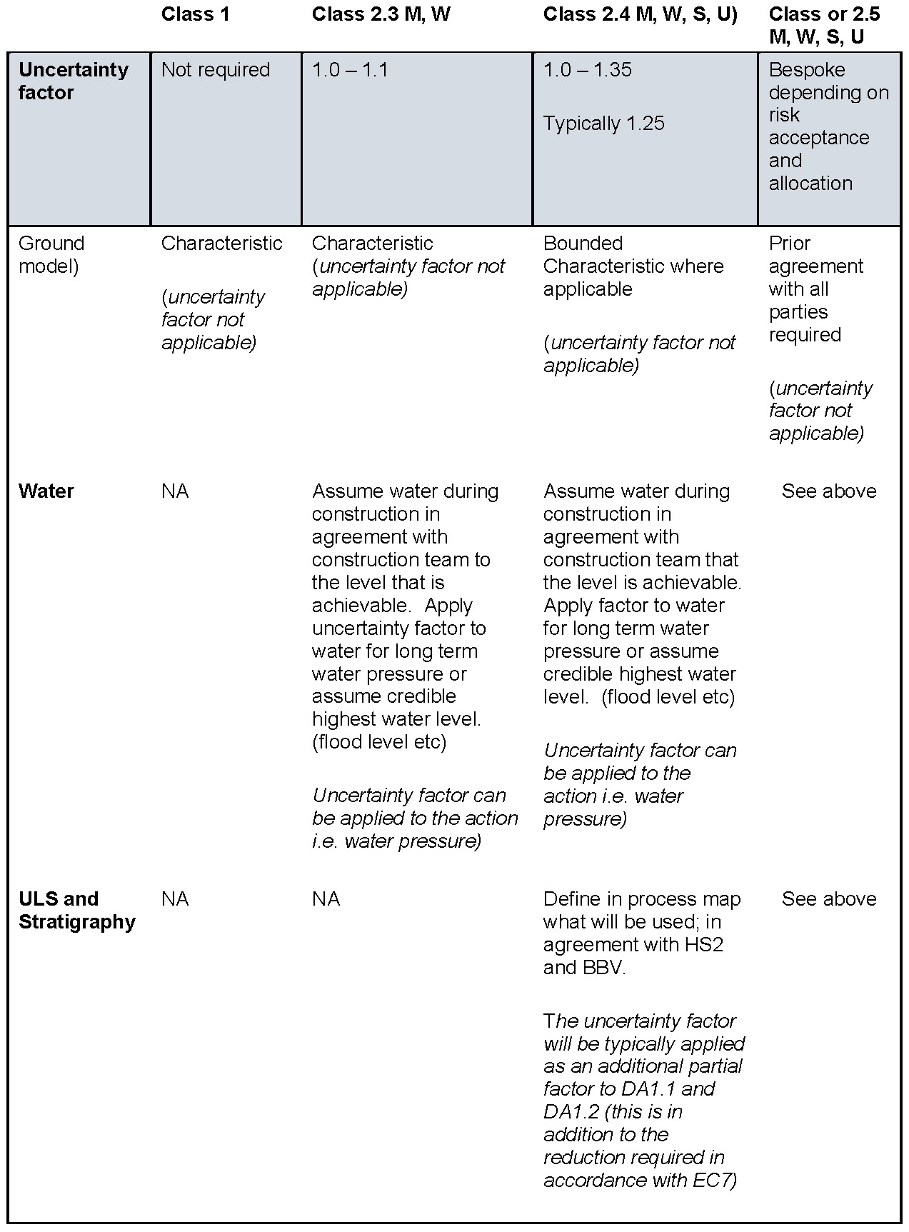
Where a bounded approach is agreed then it should include a parametric assessment to establish upper bound and lower bound solutions. The cautious solution shall be used as the default baseline solution and the optimistic solution should only be used upon agreement that practical mitigation measures are available if data shows ground to be worse than assumed in the optimistic solution. Sensitivity studies may be needed to establish whether uncertainty factors need to be used.
For Class 2.3 (m) assets, where insufficient GI information is available to provide a reasonable assessment of ground movements or SLS element related to asset (also impact on third part asset). A bound of indicative movements based on empirical methods may be provided instead. The risk will be clearly identified for such assets in the risk register.
Class 2.5 are assets that have limited information. For such assets detailed design should not be considered as a matter of course without new GI. Exceptions to these cases should be agreed with senior management of HS2/BBV/DJV prior to commencement and clear risk allocation defined prior to commencement.
To assist with detailed design, the regional parameter assessments carried out in Stage 1 have been updated for the Mercia Mudstone Group and glacial deposits to provide typical bounds of parameters and to highlight variation in parameters that occurs for the same material across Area North (around Birmingham) of the HS2 Phase One contract. These further guide selection of parameters for all classes of assets and allow assets such as Offchurch Cutting, as shown in the example, to proceed to detailed design.
Following on from the scheme design example used, Offchurch Cutting is proceeding to detailed design and using the developed classification system has been classified as class 2.3 s/w, relating to locally lower confidence in groundwater conditions and geotechnical properties. The key risks are noted as potential for:
- continuous groundwater egress from cut slopes in some areas;
- presence of cohesive lenses in Glacio-fluvial deposits; and
- poorer geotechnical properties than assumed in some areas.
There will now be a discussion between the designer and contractor as to how to manage this risk, either to undertake the additional ground investigation scheduled to obtain further information or define the asset as a Class 1* asset and use characteristic parameters that are more cautious to reflect the information available for cohesive lenses and geotechnical properties and an observational approach with respect to groundwater control. Risks will be clearly highlighted in the risk register.
Conclusions
Use of risk-based approach to geotechnical design to account for quality and extent of available ground investigation is done on all projects of all sizes. To manage project risk, all parties (designers, contractors and owners/clients) need to be realistic about available GI information and the implications at the various stages of the project.
Having a clear framework to explain the status of information and implications on the design and construction is a key part of communicating and, where appropriate, transferring the risk between the various parties. For most projects the risks associated with the amount and quality of information available will be manageable without the need for a bespoke classification scheme. For mega-projects a simple scheme to allow communication to various parties has proved valuable.
The GI classification scheme set up in Stage 1 scheme design of HS2 N1 & N2 contracts successfully communicated to management teams in several organisations (designer, contractor/client and owner) the amount of information available for design of the assets and allowed design to proceed using a common approach to the amount of information available. Difficulties were encountered during implementation of the approach, mainly common understanding of the purpose and consistent application by the design teams. However, the classification scheme was largely viewed as a positive part of the design that added value.
Based on the success of the scheme, it has been adapted for Stage 2 detailed design to aid communication of the risks associated with variable quantity and quality of ground information, and to assist in agreement of assumptions and risk management.
Based on the experience from Stage 1, for future projects it is recommended that any scheme is kept as simple as possible. It is important to highlight that all these processes don’t negate the need for thought or judgement – there will be exceptions to the rules and the rules may need refining as the project progresses.
References
[1] Vance, M. Bellhouse, M. Hepton, P. Talby, R. Lawrence, J.A.. Preene, M. Lawrence. U.L. Buckley, R. (2018). A collaborative approach to high quality ground investigation required for the design of five deep Thames Tideway Tunnel shafts. Engineering in Chalk: Proceedings of the Chalk 2018 Conference. ICE.
[2] Chandler, R.J and Forster, A. (2001). Engineering in Mercia mudstone. CIRIA C570. 2001.
[3] HS2 Ltd., Geotechnical Desk Study for Warwickshire. C223-CSI-GT-REP-000002 P06 09 May 2016.
Peer review
- Nick Sartain, Head of Geotechnical EngineeringHS2 Ltd
- Graham Church HS2 Ltd (EDP Jacobs)