Mitigating the effects of tunnelling under Euston Bridge 7
HS2 tunnels will pass below an existing main line railway intersection bridge near Euston, known as Bridge 7, constructed in the early 20th century. An assessment of tunnelling induced ground movement predicted potential adverse effects on the fragile historic structure.
The challenge for the bridge mitigation team was to develop a methodology for logistics, design, and construction of the mitigations, including confirming existing conditions during a six-week blockade below the bridge but with no interruption to the main line above. The challenge was increased by the low headroom, buried obstructions, and severely limited access and working space.
Analysis showed the masonry bridge abutments and wing walls would have low resilience to predicted ground movements. After considering several options, a mitigation was developed using prestressed ground anchors to provide a permanent restoring force to the existing retaining walls. The sequence of pre-coring, anchor installation, proof testing and stressing was closely co-ordinated with the site team.
The anchors will be continuously monitored during HS2 tunnelling construction, using an observational approach, agreed with Network Rail, to avoid overstressing the historic masonry structures.
The bridge mitigation works included the creation of gaps at the back of the main girders at both abutments to let the bridge deck slide over the bearing plates, and some localised steelwork strengthening to enable the bridge to resist differential settlements. Finally, jacking systems were inserted beneath the six westernmost columns to mitigate against unforeseen ground movements.
Careful selection of methods helped to manage risks during site works and severe programme risks associated with overrun of the blockade. Work was successfully completed within the six-week blockade.
- Written by
-
Alberto Carlucci (Arup/SCSjv)

-
Samantha Godden (Arup/SCSjv)

-
Aneeka Barmi (Skanska/SCSjv)

-
Ben Cox (Skanska/SCSjv)

-
Jay Master (Skanska/SCSjv)

-
Angelina Damianou (HS2 Ltd/SCSjv)

-
John Collins (HS2 Ltd/SCSjv)

- Resource type
- Resource type: Technical Paper
- Intended audience
- Consultants
- Contractors
- Public Sector Clients
Introduction
This paper is presented as part of the works to deliver the Main Works Civils Contract (MWCC) for the southern section of High Speed Two (HS2) Phase One which includes the Northolt Tunnels and the Euston Tunnel and Approaches, being delivered by the SCS Integrated Project Team.
HS2 Contract S1 (Euston Tunnels and Approaches) involves the construction of tunnels to connect the HS2 running lines into the new low-level terminus in Euston, London. As part of this contract, three new SCL tunnels (the “crossover tunnels”) are to be constructed directly beneath the existing Network Rail main lines just north of Euston station (Figure 1).
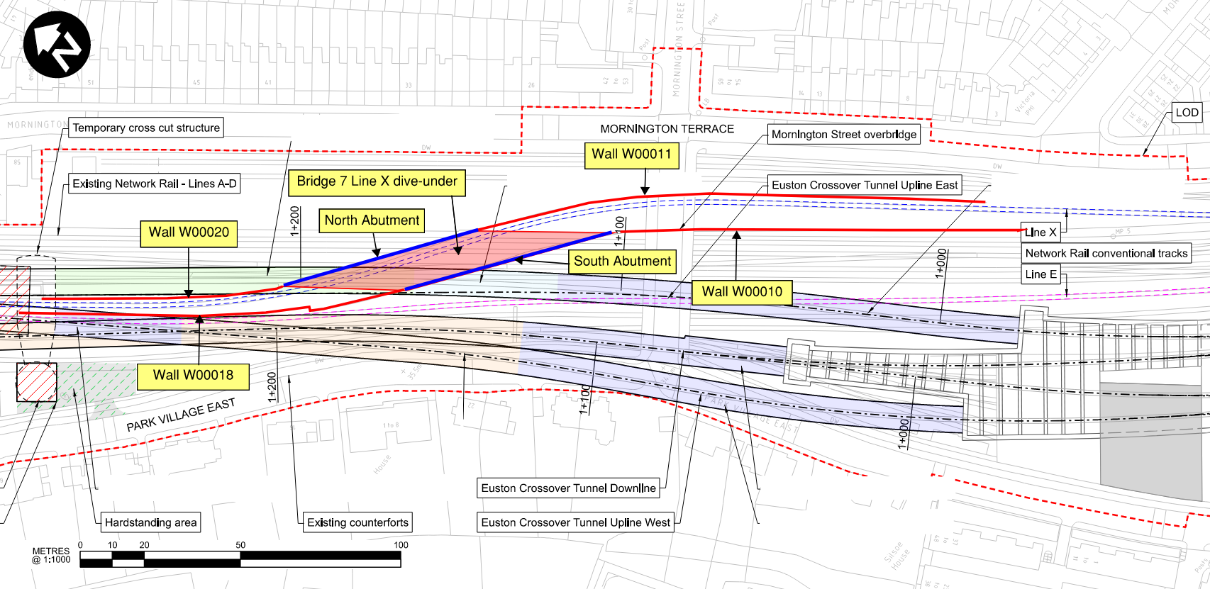
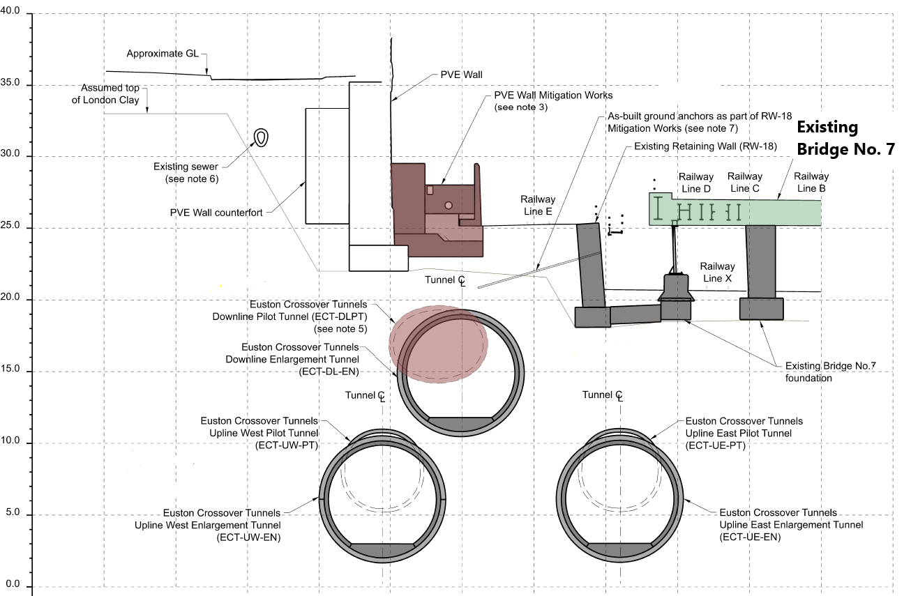
The crossover tunnels will run in close proximity to an existing Network Rail intersection bridge (ELR LEC1 0m 1147y) “Bridge 7”, which enables “Line X” to cross beneath four of the main lines leading to Euston’s platforms. The bridge is within the zone of influence of all three HS2 tunnels as shown in Figure 2.
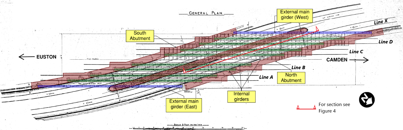
Bridge 7 was constructed between 1902 and 1904 as part of the extensive programme of works carried out by the London & North Western Railway to widen and improve the approach to Euston Station. It is a highly skewed, two-span riveted steel structure (Figure 3). The deck comprises two main longitudinal external girders and four pairs of longitudinal internal trough girders, one pair supporting each main line track A, B, C and D. The rails are supported on ballast and concrete, or timber sleepers. Lines A to D and X are all AC overhead electrified; lines C and D are also 3rd rail DC electrified.
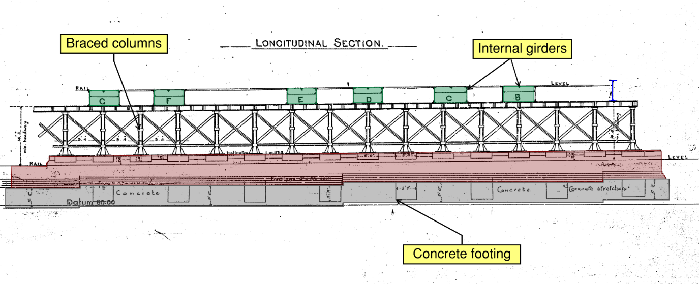
The main girders span continuously between abutments and are bolted to a central pier. The abutments are solid masonry gravity retaining walls with concrete footings and stone capping to support the girder bearings. The central steel trestle of braced vertical columns is supported on bedstones and a masonry foundation with a concrete footing (Figure 4). The abutment and pier footings are propped at foundation level by concrete stretcher beams (Figure 5a).
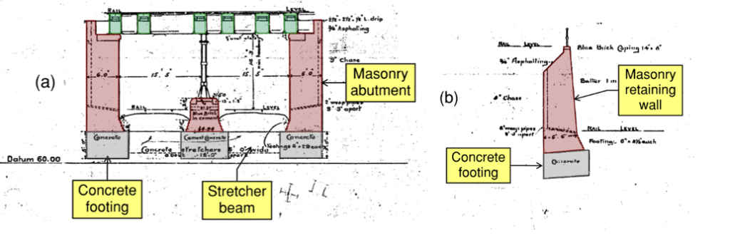
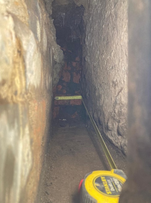
Approaching Bridge 7 from the north and south is a retained cutting, supported by solid masonry gravity retaining walls with concrete footings (Figure 5b). These are separate numbered assets: W00010 and W00011(south), W00018 and W00020 (north) as shown in Figure 1. The bridge and approach walls together are known as the “dive-under” structure. Originally, the dive-under carried two lines, but as part of the Euston Remodelling works in 2000, the northern approach was narrowed with a new concrete wall and the line under the south span was lifted.
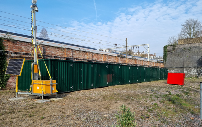
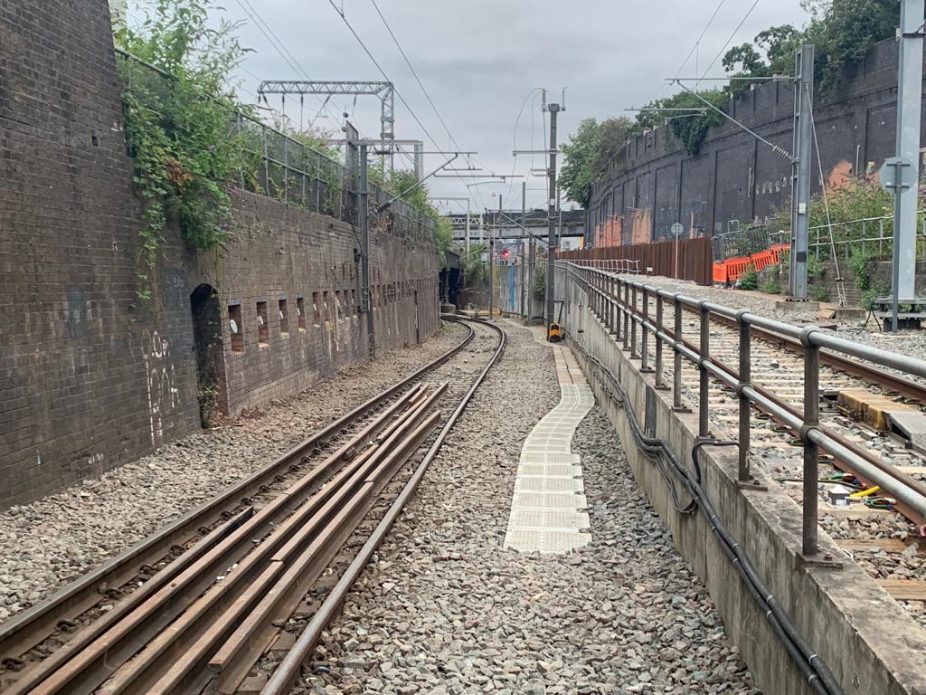
Figure 6, Figure 7, and Figure 8 show Bridge 7 and the dive-under before mitigation works.
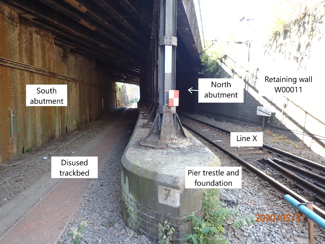
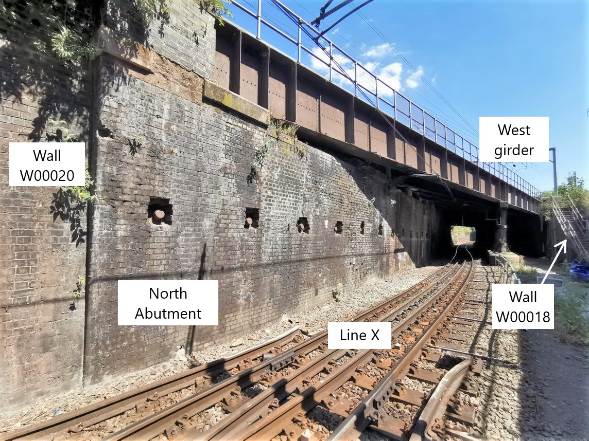
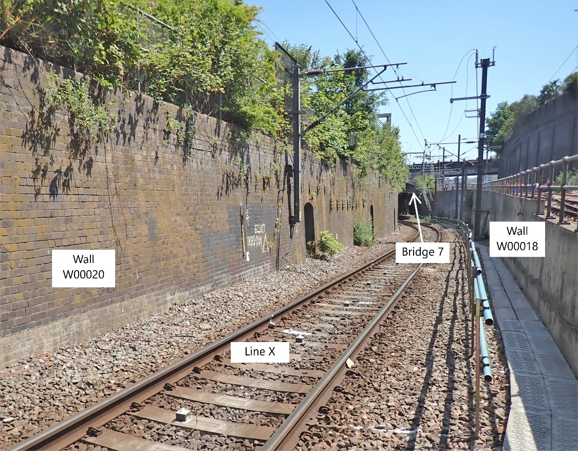
Following inspections, the masonry abutments and retaining walls were found to be in generally fair condition, but with some long-standing defects and evidence of previous movement. However, the bridge deck and pier trestle were in poor condition with many defects, including widespread loss of section due to corrosion, missing rivets, and distortion of the internal girders. The ends of the main girders had been encased in concrete, obscuring the bearings. The north abutment was leaning significantly, and two rows of ground anchors had already been installed (Figure 7).
It was concluded that the bridge was in a fragile state and vulnerable to damage due to any further settlement or distortion imposed by the HS2 tunnelling works. The bridge is critical to Network Rail’s operations, as all six Euston lines run over, under or next to it. It was identified as a priority to keep the bridge open throughout the HS2 tunnel construction works, with appropriate mitigation works if required.
A six-week blockade below the bridge between 16th July to 30th August 2021 was booked two years in advance with the plan to carry out any potential mitigation works. The challenge for the bridge mitigation team was then to develop a methodology for logistics, design, and construction of the mitigations during the six-week blockade below the bridge, but with no interruption to the main lines above.
To inform this process, a detailed ground movement assessment was put in hand.
Ground Movement Analysis
Due to the complex geometry of the HS2 works and the sensitivity of Bridge 7, a finite element (FE) analysis using LS-Dyna software was chosen to model the ground movements due to HS2 construction and tunnelling works. The non-linear BRICK constitutive model was adopted for the London Clay [2].
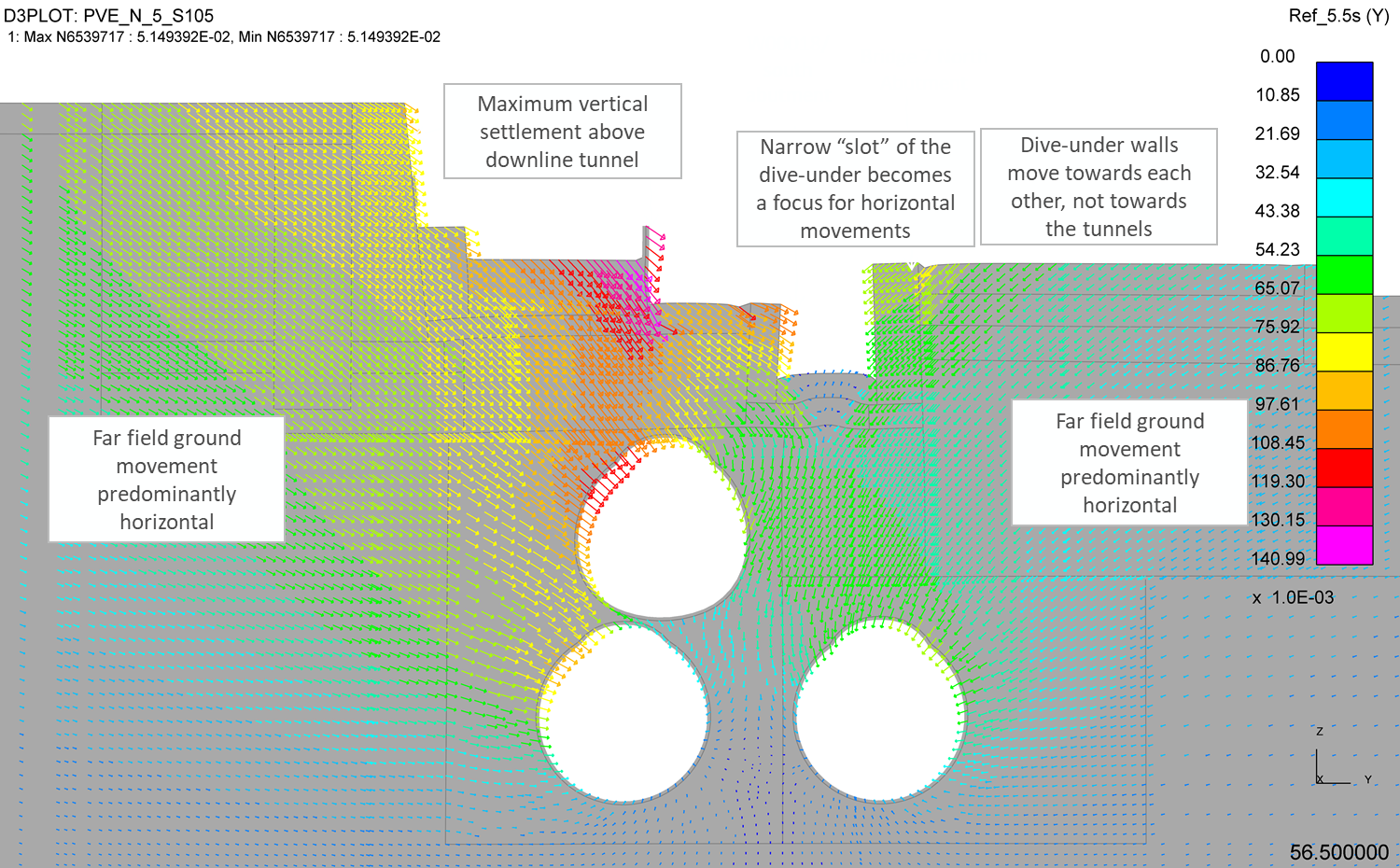
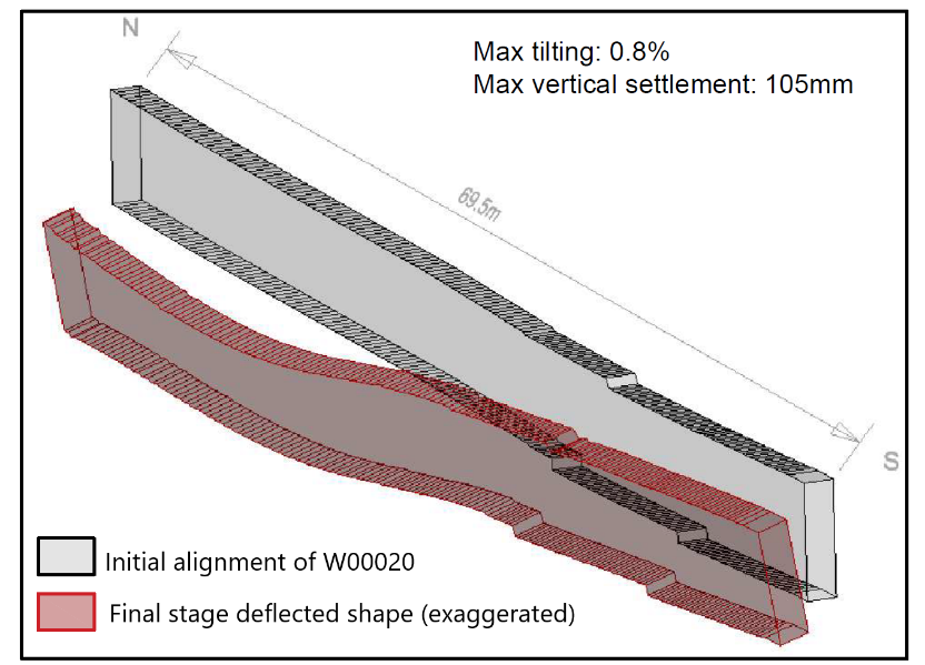
The model predicted that, in addition to the expected vertical settlement, the construction of the HS2 tunnels would cause a general inward movement of the soil towards the tunnels, extending for some distance to each side. This was considered to be a result of the high in-situ horizontal stresses (high K0) which are characteristic of the over consolidated London Clay. Excavation of the tunnels causes a reduction of horizontal stress, and corresponding inward movement of soil. Above the tunnels, this inward movement is seen as translation and tilting of the unpropped walls of the dive-under (Figure 9).
Ground movements at the top of the abutments (bearing level) and the base of the central pier were extracted from the analysis to investigate possible distortion or overstress in the bridge structure and are summarised in Figure 10 and Figure 11.
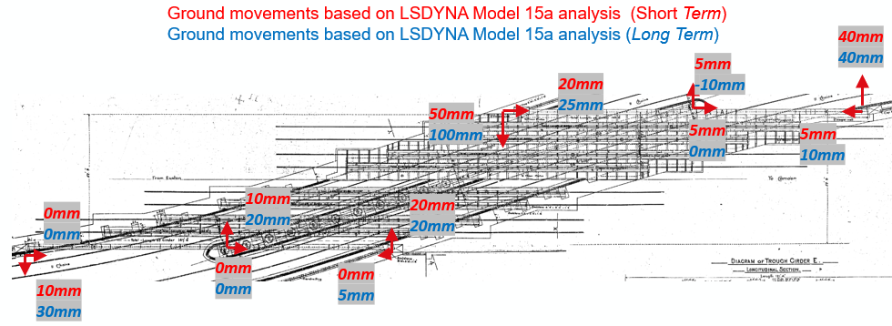
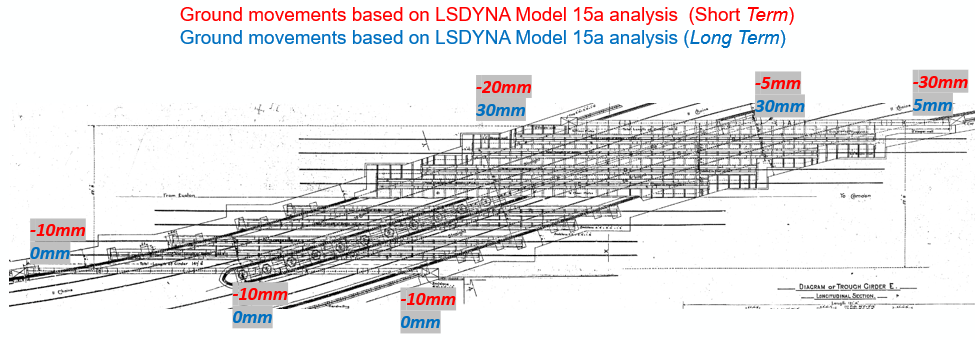
It was noted that whilst the global trend of ground movements was towards the HS2 tunnels, the resultants of the X and Y movements were consistent with the top of the abutments moving directly towards each other. Also, the deflection profile along the abutments was broadly linear from east to west, but the centre pier had an irregular movement profile and of a different magnitude to the abutments. This was found to affect the bridge structure and required advanced structural analysis to identify the elements requiring mitigation works.
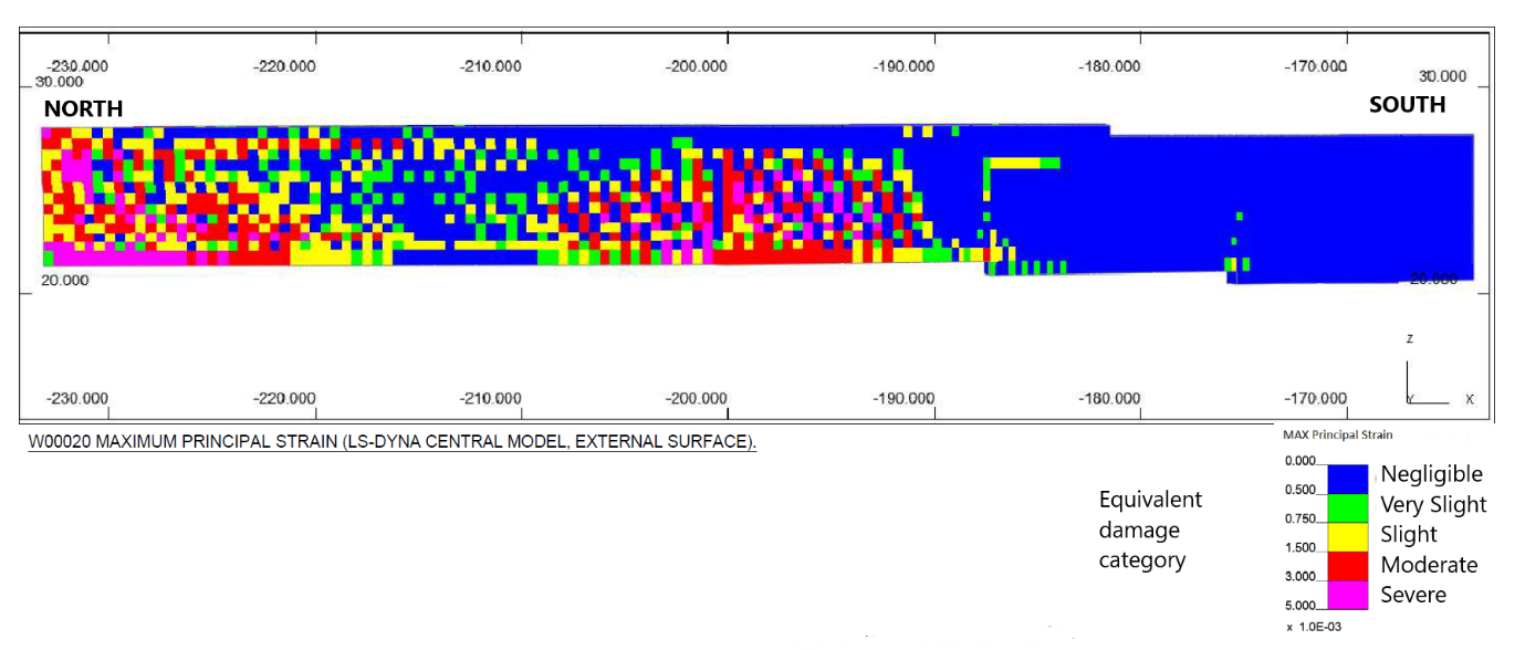
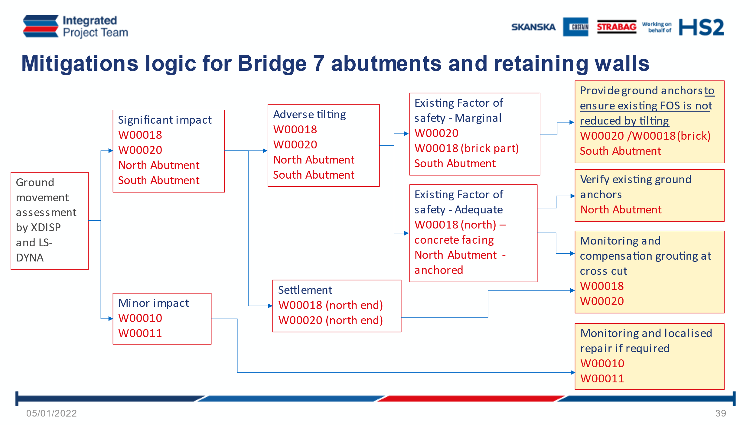
The masonry abutments and approaching retaining walls were assessed for the effects of ground movements. The strains in the masonry generated by the ground movements were assessed using the Burland damage categories[1]. The retaining walls were mostly in Damage Category 2 (Slight) apart from the northern sections of the dive-under walls (W00018 and W00020) which are subject to settlements of up to 105mm above the SCL cross-cut tunnel, and locally up to Damage Category 5 (Severe).
The tilting of the retaining walls was also a concern for wall stability, by increasing eccentricity of the load on the foundations. Following assessment of the existing conditions, some of the bridge abutments and wing walls were found to be undersized according to modern design codes (Eurocode 7) and could only be shown to have a marginal factor of safety in back-analysis. It was considered that these walls were unlikely to be able to safely accommodate the predicted tilting, particularly as some had already exhibited considerable historical movement.
Design of Mitigation Works
Mitigation Works Strategies
The Ground Movement Assessments concluded that the bridge structure and the abutments, including the wing walls, required mitigation works to preserve the safety of the asset during the HS2 tunnels construction.
The Bridge 7 asset mitigation works were planned to be carried out in two phases, prior HS2 tunnels construction and during HS2 tunnels construction (Table 1).
Prior to the commencement of any mitigation works, monitoring instrumentations were installed and monitoring data was collected to ensure that sufficient baseline monitoring data is available to be able to distinguish between signals due to the future HS2 tunnelling works activities and the natural signals or inherent noise.
| Mitigation Works prior to HS2 tunnels construction
(To be carried out during six-weeks Line X blockade). The following mitigation works were designed to be built prior to the HS2 tunnel construction, to prepare the asset to receive the additional effects induced by the predicted ground movements caused by the HS2 tunnelling construction:
|
| Mitigation Works during HS2 tunnels construction
During the tunnelling construction phase, the following mitigation actions are planned:
|
The following paragraphs describe the process which led to the design of the Bridge 7 mitigation works.
Bridge Structural Analysis
The Bridge structural analysis was carried out with the software Oasys GSA with the objective to determine the effects of the predicted ground movements on the steel structure (Figure 14, Figure 15 and Figure 16).
The effects of the predicted ground movements were considered in the global models by inputting them as applied displacements at the abutment bearings and at the bases of the pier trestle. These effects were added to the effects of the permanent loads and of the train live loads considering the Route Availability (RA) 10 in accordance with the Network Rail requirements for this asset.
The steel structure had been assessed by comparing the load effects determined with the global models against the capacity determined in accordance with the relevant Network Rail standards [3].
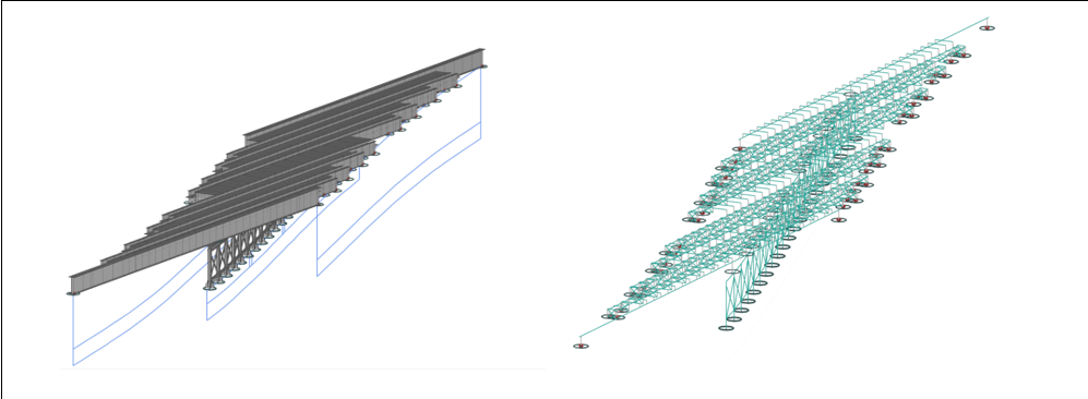
Figure 14. Bridge 7 Grillage model
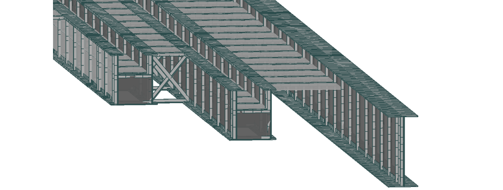
Figure 15. Bridge 7 Shell model.
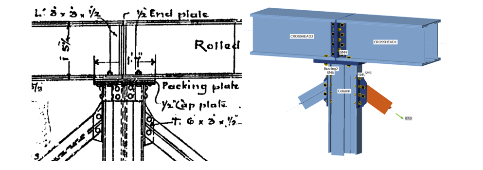
Figure 16. Example of Ideastatica model for Pier Crosshead connection
The outcome of the Inspection for Assessment carried out in 2020/21 was also included in the analysis, in particular by considering the section losses due to corrosion and the historical deformations within the pier trestle.
The first step of the bridge structural analysis was to determine the baseline level of utilisation of the bridge structure (i.e., ignoring any effects due to the predicted ground movements induced by the tunnelling). This confirmed that the steel structure was a fragile structure with some more critical elements (i.e., the main longitudinal girders over the pier support and the pier crosshead beams).
The subsequent analysis including the effects due to the predicted ground movements indicated that overall, the steel structure had enough capacity reserve to be able to resist these additional effects without requiring any strengthening works except for selected areas of the pier crossheads and of the longitudinal girder B1.
Design of Bridge Strengthening Works
The Bridge structural analysis indicated that steel strengthening was required for:
- The main longitudinal girder B1 over the pier support
- The pier crosshead in the midspan region of beam, from west end, Nos: 3, 4, 5, 7, 19.
For both strengthening works, the focus area was close to where the largest ground movements were predicted (i.e., at the west end closer to the HS2 tunnels).
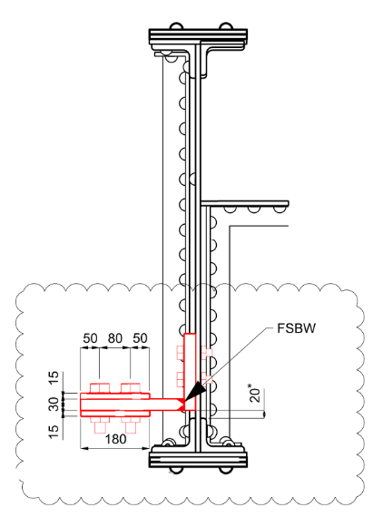
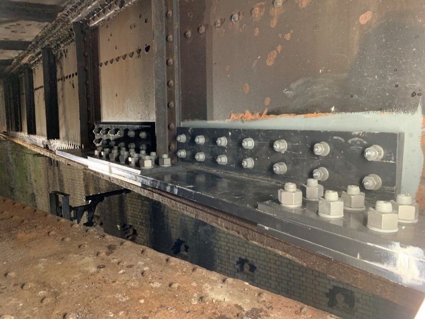
The objective of the steel strengthening works of the main longitudinal girder B1 over the pier support was to increase the hogging moment capacity by adding an L-section bolted to the accessible side of the girder web for a length of approximately 6 m (Figure 17).
The new steelwork was carefully designed to avoid any clash with the existing web stiffeners and it was split into several shorter and lighter segments to ease installation (Figure 18).
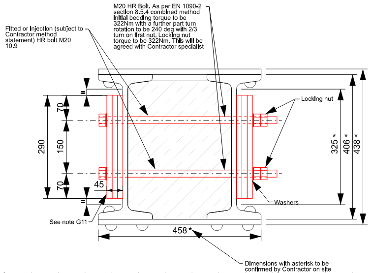
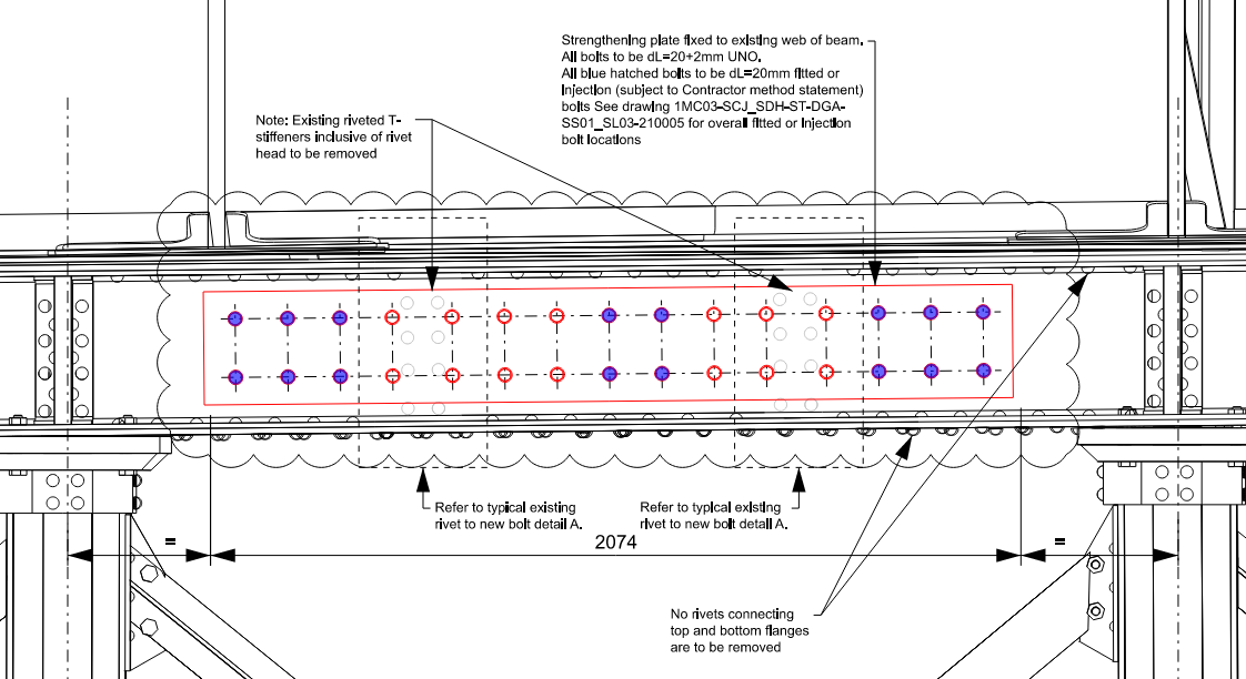
The objective of the steel strengthening works of the pier crossheads was to increase the sagging capacity of the section by adding steel plates to both sides of the hollow section, to be bolted through the concrete infill and the side webs (Figure 19 and Figure 20).
Design of Jacking System for Central Pier
Provision was made for a jacking system under the bases of the six westernmost columns of the central pier trestle, which will be activated for mitigating settlement if ground movements reveal to be larger than predicted during the HS2 tunnelling construction.
In this event, the jacking system will allow the base of the columns to be jacked up or down by +/-20 mm to reduce the demand on the main longitudinal girders.
The design indicated to install the jacking system underneath the base of the columns within a diagonal cavity defined to ensure the stability of the column base even during the temporary excavation sequence.
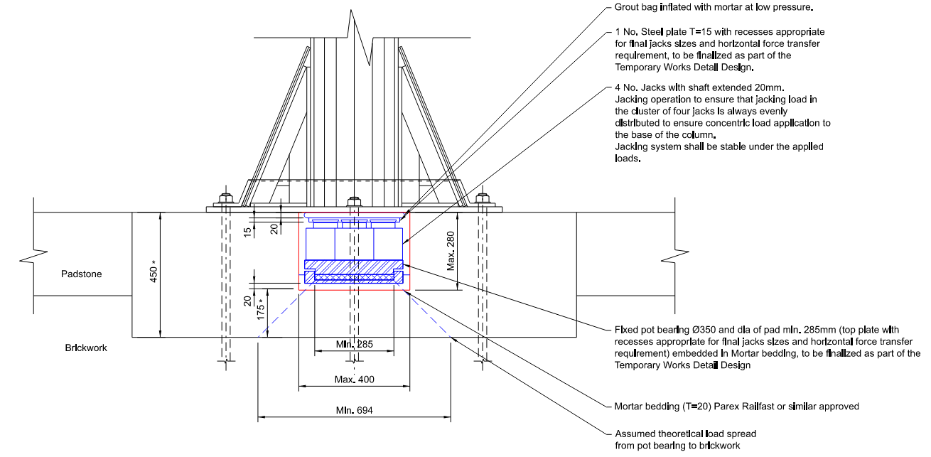
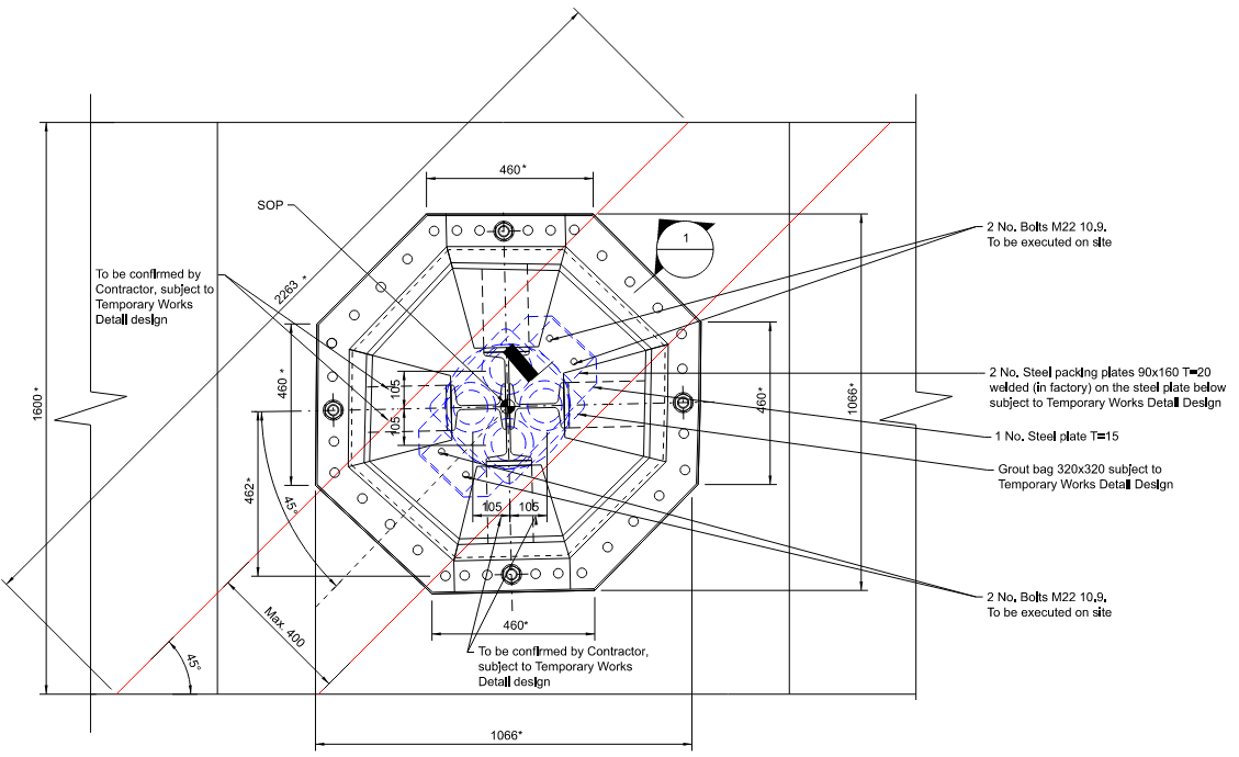
The jacking system comprises a pot bearing sitting on a bed of mortar, with the double objective to allow the required +/-14 mrad rotational demand required at the base of the columns, and to spread the load coming from the jacks above uniformly over the mortar bed and the bedstone underneath.
The pot bearing top steel plate has some recesses machined to accommodate four jacks to be installed with the shaft already extended 20mm. The jacks are covered at the top with a steel plate, bolted to the underside of the existing base plate, with an additional intermediate layer of grout bag to ensure a smooth load transition between the existing base plate and the jacking system (Figure 21 and Figure 22).
During the HS2 tunnelling works, if the jacks are required to be operated to jack the column up, then the existing holding down bolts will be unlocked, and the jacks will be able to operate.
Vice versa, if the jacks are required to be operated to jack the column down, then in addition to unlocking the existing holding down bolts, an additional uniform cavity will have to be created underneath the full extent of the existing base plate and new holding down bolts will have to be reinstated at the end of the works.
Design of Ground Anchors for Bridge Abutment and Wing Walls
The mitigation works to the retaining walls and abutments were prioritised according to the severity of impact and the existing stability. The north abutment of Bridge 7 had existing ground anchors, which would improve its resilience. The northern portion of wall W00018 has a substantial concrete facing, which increases its width and therefore, its stability. However, wall W00020, the southern (masonry) portion of W00018 and the Bridge 7 south abutment were found to have marginal stability, and therefore mitigations were proposed (Figure 23).
The retaining walls were divided into five design cases to cover the range of existing geometry, and the design anchor force was selected for each cross section, as the lower of:
- Highest force that would not fail shear stress checks in the masonry to Eurocode 6 (Design of masonry structures) at proof load, either Serviceability Limit State (SLS) or Ultimate Limit State (ULS)
- Lowest force needed to provide geotechnical equilibrium at SLS and ULS to Eurocode 7 (Geotechnical design)
For the tallest retaining wall sections, condition (i) was critical, i.e., the limit of masonry shear stress was reached before the geotechnical ULS conditions were satisfied. Noting that the existing conditions were already non-compliant to modern codes, it was agreed with Network Rail that the stability of the walls would still be significantly improved by the lower anchor force, and that the adverse effect of the predicted tilting would still be mitigated.
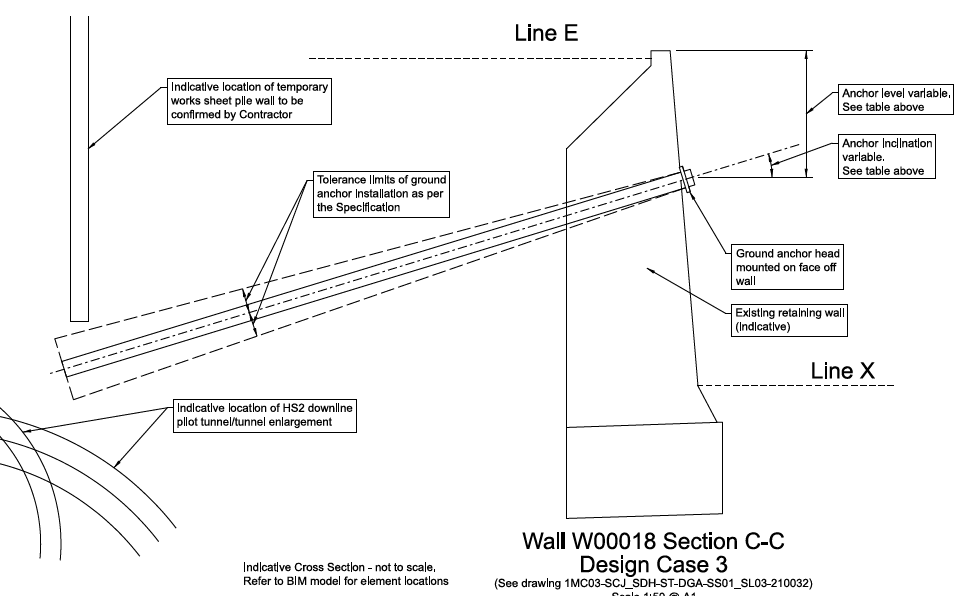
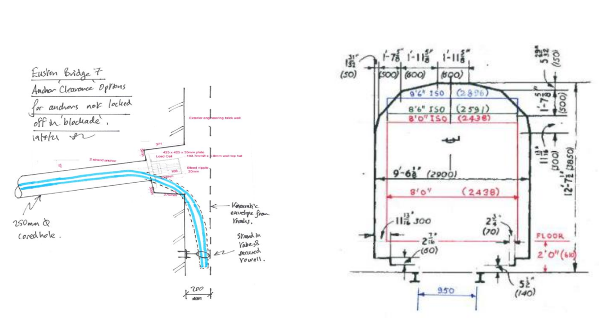
From the SLS and ULS checks, for each design section the Designer specified the anchor design forces Fserv,k and FULS,d , the anchor head position, minimum/maximum anchor length, minimum/maximum spacing and inclination (Figure 24).
The ground anchor elements were designed by SCS’ specialist subcontractor Keller Ltd. Informed by preliminary sacrificial load tests, the anchors were designed using the Single Bore Multiple Anchor (SBMA) system to gain maximum performance from the fixed lengths. Keller also designed the individual anchor capacity and therefore the spacing along the wall (Figure 25).
The ground anchors were constrained by existing Network Rail deep drainage and gantry foundations, identified from surveys and historic drawings, as well as HS2 temporary and permanent works. Ideally, ground anchors are offset several metres from other buried assets to avoid interaction with the fixed length. A detailed clash avoidance exercise using the 3d BIM co-ordination model enabled the anchor layout to be fine-tuned to achieve this.
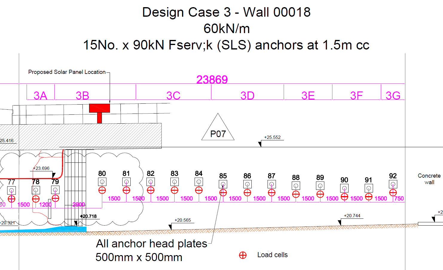
For the anchors in Wall W00018 and the south abutment, the clearance to the HS2 Downline tunnel had to be reduced to as little as 600mm, or the anchors would have been too short to provide a restraint to the retaining wall. The behaviour of the fixed lengths installed in a zone of ground subject to deformation and stress changes is complex, therefore, the interaction between the line of anchors (installed first) and the downline tunnel construction was investigated in LS-Dyna. This showed the closest anchors could experience large load fluctuations as the tunnel face approached and passed. There was a risk of excessively high anchor forces that could over-stress the retaining walls during this stage, so continuous monitoring by electronic load cells and fully restressable anchor head assemblies were specified for all anchors in the vulnerable zone.
To ensure the ground anchors remained close to the design load throughout the HS2 works, i.e., both providing the meaningful support to the walls but not overstressing the fragile structures, a monitoring approach based on the Observational Method was developed. Each design section had a specified range of acceptable anchor load between 50% Fserv,k and 100%Fserv,k. Should the monitoring show the anchor forces approaching the upper or lower limit, they will be re-tensioned to increase or reduce the pre-stress appropriately.
Construction of Mitigation Works
Construction and site challenges
The greatest challenges were associated with the logistics of accessing Bridge 7.
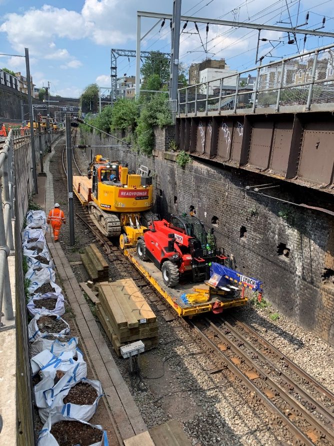
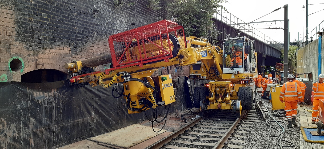
As with most rail construction sites, deliveries and waste removal took place via Road Rail Vehicles (RRVs) (Figure 26) accessing the railway at Road Rail Access Points (RRAPs).
Plant could only be operated when isolation of the relevant railway lines was in place. In accordance with rail safety standards [4], people, plant and equipment could not encroach within 2.75m of live Overhead Line Equipment (OLE) due to risk of electrification.
Euston’s pre-determined Possession Schedule dictated railway line isolations which regularly changed to meet NR’s operational requirements.
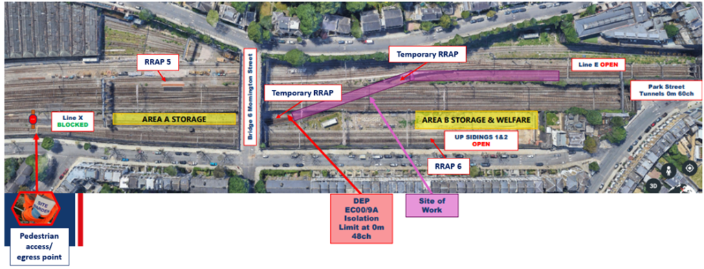
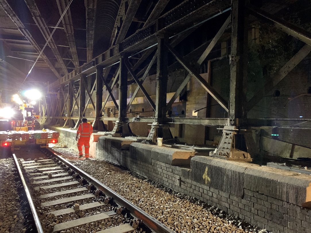
Throughout the six-week Line X Blockade, a ‘Section C’ isolation ensured the Bridge 7 worksite was safe to work in. However, the adjacent railway lines remained open and operational (Figure 27) apart from at weekends and selected night shifts when additional possessions and isolations of some lines were available. This meant all deliveries and waste removal activities had to be meticulously programmed within these times. As space at Bridge 7 was constrained, plant movements, material and waste quantities were modelled in advance of the blockade and regularly re-evaluated to avoid supply and space issues.
As possessions times are fixed and agreed with train operating companies in advance, there was challenge in ensuring construction was completed to programme. This was considered in the design phase where mitigation and material choices focussed upon ease of installation to ensure efficient construction methodologies. A Quantitative Schedule Risk Assessment (QSRA) was undertaken with a Time Risk Allowance included to minimise potential disruption to the train companies. A Blockade Management Plan and a Contingency Plan were produced to ensure successful management of the programme and that works could be safely stopped with no impact to the structures or train operation if required.
Fatigue management was crucial through six weeks of 24/7 working. The team was rostered to ensure adequate rest periods and the impact of COVID-19 was accommodated. A particular success was a direct phone line available to the Designer so that technical advice could be provided promptly.
Preparatory Site works in advance of Line X blockade
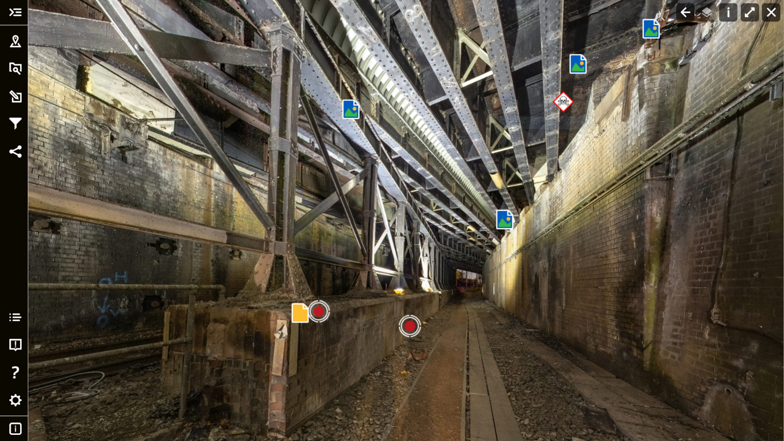
Due to the structures age and condition, extensive structural surveys were carried out to inform the Designer’s approach. Access was limited by the possession schedule and COVID-19 restrictions, whilst night hours gave poor visual conditions. Therefore, a 4D photogrammetry model was commissioned so that the structure could viewed in detail at all times (Figure 28).
As Bridge 7 was outside the SCS worksite, the worksite had to be completely self-sufficient. A temporary compound was set up (Figure 29), vegetation was cleared, pedestrian access routes established and a working platform with two temporary RRAPs installed for the plant required (Figure 30). Power and lighting were also install to support the mitigation works constructed.
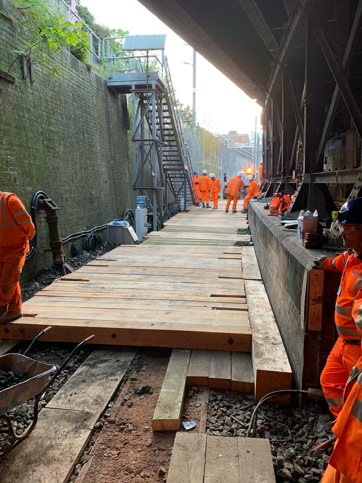
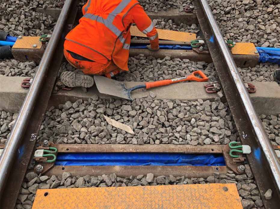
Particularly effective were the hollow-bearers installed to an adjacent railway line that was operational during the blockade (Figure 31). This allowed pipework to constantly supply grout and water to the Bridge 7 worksite.
Construction of Bridge Strengthening Works
The bridge strengthening works required the re-creation of gaps at the back of the main girders and the installation of 3t of structural steelwork to Girder B1 and the pier crosshead.
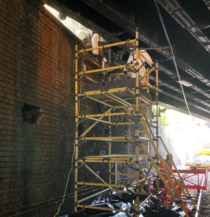
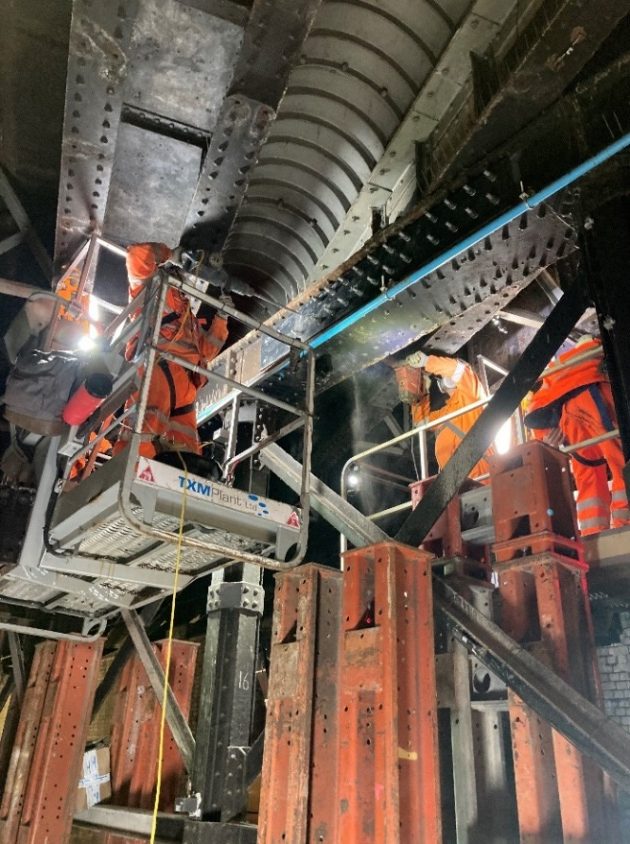
Where debris was to be removed ‘re-create’ the gap at the back of the main girders, access towers were utilised to manually clear the ends. Where concrete encased the ends of the main girders, it required brickwork to be broken out at height in a constrained space (Figure 32). Hydro demolition was initially considered, however, it would have been impractical to supply the required amount of water. Additionally, a Low Voltage (LV) cable mounted to the wall beneath and could have been adversely impacted from runoff introducing a safety hazard. Therefore handheld concrete breakers were utilised (Figure 33) and Operatives wore face fitted FFP3 face masks as a mitigation against the dust created. The task was rotated between multiple operatives in accordance with a Hand Arm Vibration Syndrome (HAVS) Risk Assessment to minimise the occupational health hazard.
For the pier crosshead, the steelwork was fabricated into a set of 15mm plates to achieve the 45mm thickness required. The reduced weight allowed for easier manual handling and installation at height. The plates were installed using an RRV Mobile Elevated Working Platform (MEWP) (Figure 34). As structural surveys had shown the structure was in relatively poor condition, lifting aids fixed to the existing structure could not be considered. Girder B1 steelwork was installed similarly with an additional forklift to assist due to their larger weight (Figure 35).
Particularly noteworthy was the decision to undertake a clash detection using point cloud data and pre-drilling holes in the steelwork during fabrication saving time and difficulty with alignment on site. Similarly, the plates were pre-painted off site beforehand to reduce exposure and improve curing times on the programme.
Construction of Jacking System for Central Pier
Installation of the jacking system was considered the most technically complex element of the design. Regular workshops were held between the specialist subcontractor, contractor, and designer to develop a feasible design and mitigate potential risks prior to works.
The column bases were strengthened before recesses were formed beneath each of the six column baseplates through a combination of wire sawing and coring (Figure 36). Jacks, connected with steel plates, were positioned onto a bearing set in mortar with a 2.5mm tolerance. To provide an even contact pressure to the base of the column, a grout bag was installed above the jacks and filled with grout. Once sufficiently cured, the jacks were preloaded using a specialist Synchro-pump (Figure 37).
During a series of trials, the original high strength anti-shrink grout selected to fill the bag set prematurely. Through experimentation, a grout capable of achieving the 60MPa within the programme was selected.
The most onerous constraint was that each installation had to completed under possession of one of the overlying railways lines. There were only six weekends during the blockade where 50-hour possessions were available to complete six installations. The works had to be completed prior to reopening the line above. Once the installation commenced, the only contingency for overrun would have been to halt the running of trains until works were complete. This would have had significant public, financial and reputational impact. Although never used, a contingency propping system was collaboratively developed between the Designer, Contractor and Specialist Subcontractor in case of overrun.
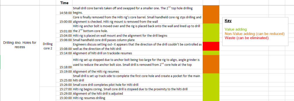
Prior to commencing, relaxations to the constraints of the first two columns were achieved allowing their installation outside of possessions. A detailed as-built programme was captured during installation to manage the risk associated with the remaining four. Whilst possible within 50 hours, SCS implemented changes by scrutinising where time was lost enabling the remaining columns to be completed in under 37 hours (see Figure 38).
A series of hold points were held during the weekend between the site team, Technical Leads and Senior Management to evaluate progress and confirm works were continuing. A WhatsApp group further aided updates and communication across the project team to develop confidence in proceeding with these high risk works.
All jacks were installed successfully with no impact to the operational railway (Figure 39).
Construction of Ground Anchors for Bridge Abutment and Wing Walls
The Line X Blockade Programme was primarily driven by the need for 92 ground anchors to be installed ranging in length from 10m to 19m. Ground anchor installation was the driver of the Line X Blockade programme due to the quantity of anchors required.
The subcontractor delivering the works was also responsible for detailing the ground anchors in line with the Performance Specification provided by the Designer. Although 108 ground anchors were initially proposed, a sacrificial test anchor was installed in advance of the blockade in an area of site with similar ground conditions. The findings allowed a lower Factor of Safety to be used so that the design could be reduced by 16 anchors. Whilst reducing the material, financial and environmental costs, the test anchor provided the team with valuable experience and knowledge for the programme ahead.
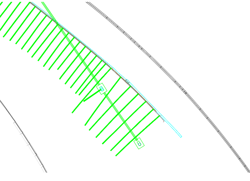
During detailed design of the ground anchors, locations were coordinated with known obstructions such as sheet piles from other works and the future tunnels using 3D modelling (Figure 40). During construction, several unexpected obstructions were encountered, resulting in delays whilst the ground anchor spacing was re-designed to suit. In one instance, the asset owner agreed that the obstruction could be cored through as the concrete encountered was a redundant foundation.
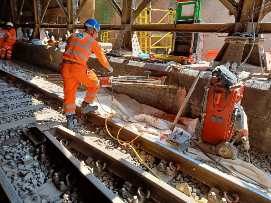
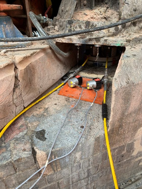
Approximately 2m of brickwork had to be cored through before the ground anchors were installed using a specialist rig (Figure 41). Each took a few hours and some Victorian back-of-wall drainage pipes were penetrated. In these instances, casings were sacrificed to prevent grout leakage into the drainage channel and provide a waterproof seal when the anchors were grouted in. Once the grout sufficiently cured, the anchors were stressed, tested, and locked off with a head plate and a protective cap.
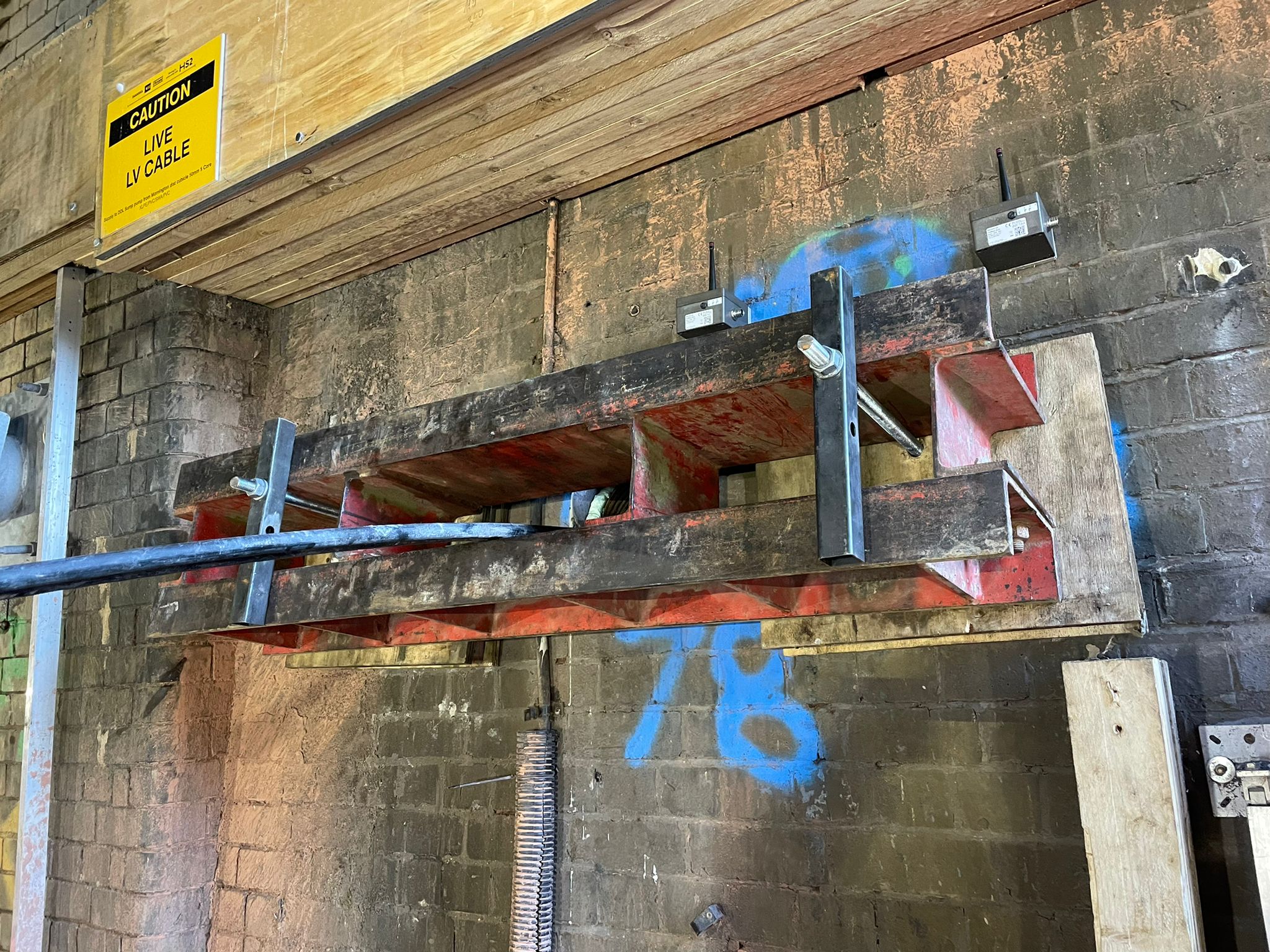
Design uncertainties dictated a sequence for coring, installation and stressing so that the masonry wall thickness could be verified. Where the wall thickness was significantly less than expected, a temporary spreader beam was used to distribute stressing and testing loads on the anchors and reduce the risk of punching failure (Figure 42).
These constraints induced further complexity due to the tight space beneath Bridge 7 and re-programming needed for additional works.
A kinematic clearance assessment showed that all the ground anchors in wall W00020, adjacent to Line X, would need to be completed by the end of the blockade (Figure 43) to prevent any operational impact to the railway. 61 anchors were planned for installation during the blockade, with the remainder planned for contingency possessions. Due to success and momentum gained, however, all 92 were installed within the six weeks and Line X was able to successfully reopen to trains on time (Figure 44).
Conclusion
The successful completion of the Bridge 7 mitigation works installation was the culmination of over 18 months’ collaborative teamwork. Some examples of good practice and learning points are captured below.
- The start of Covid-19 restrictions in March 2020 meant the team had to quickly engage with digital tools to communicate and collaborate virtually whilst working remotely or from home. These skills will continue to provide efficiencies in future, for example by reducing travel to meetings or the need for site visits.
- When making alterations to an existing asset, timely and accurate information about the geometry, condition and surroundings is crucial. Network Rail’s archive records, physical investigations, structural inspections, topographical surveys and 4D photogrammetry model were all used to inform and de-risk the design and construction. Early planning for surveys that need lineside access is essential, particularly where possessions and access are restricted.
- The 3D BIM co-ordination model was an essential tool for co-ordinating the work of different teams, as an authoritative point of reference for existing and proposed assets. In terms of clash detection, where potential obstructions were identified at a late stage, adding them into the BIM model enabled design adjustments to be made with confidence. Existing surveyed features (including buried assets and foundations) must be included in the BIM model as well as new design elements, so effective clash detection can be managed.
- Mitigation to a third-party asset such as a Network Rail bridge needs to follow the asset owner’s assurance process as well as the main client procedures. As the programme was already challenging, milestone dates for design outputs, Category 3 checks and Network Rail approvals were identified early on, working back from the blockade dates which were fixed well in advance. The ground anchors were a contractor-designed element and needed time for specialist designer input and verification after procurement. Regular focused and collaborative meetings between all parties involved were successfully used to ensure “no surprises” in the final submissions.
- Bridge 7 is a historic asset, already 120 years old, which is a good design life for even a modern bridge. Like many historic railway assets, it continues to be relied on as part of the rail network. The mitigations work will not only provide protection from the effects of the HS2 tunnelling but may also be adopted to extend its useful life and could even be sustainably re-used in the design or to aid constructability of a future replacement bridge.
- Maximised use of available possessions prior to the blockade increased familiarity with possession and site challenges. This increased the team’s capability, accuracy of programmes, opportunity to innovate and reduced scope within the blockade. Off-site trials for complex construction activities and hour-by-hour sequencing mitigated technical, programme and quality risks.
- The construction techniques and lessons learnt are being utilised for other mitigation works in the Euston Approaches, with benefits already being realised.
- Adherence to HS2 values, namely respecting communities, and championing collaboration, built strong relationships between teams and stakeholders. An agile team mentality was key in adapting to unexpected design and construction challenges. This was enabled by regular meetings, transparent communication, 24/7 lines of communication and an adequately resourced roster with clear accountability.
Acknowledgements
The authors acknowledge the contribution of the following to the design and construction of the Bridge 7 Mitigation Works.
- COWI (Cat 3 Checker)
- Keller Ltd/ Byland Engineering Ltd (ground anchor subcontractor/designer)
- Freyssinet (jacking/ steelwork subcontractor)
- TECS (general labour)
- Readypower (provision of rail plant)
- Network Rail
- HS2 Ltd.
- London Borough of Camden (consents and noise mitigation)
Notation
Fserv,k Characteristic value of the maximum anchor force, including effect of lock-off load, and sufficient to prevent a serviceability limit state in the supported structure.
FULS,d Design value of the anchor force required to prevent any ultimate limit state in the supported structure.
References
[1] Burland, J., & Wroth, C. (1974). Settlement of Buildings and associated damage. SOA review. Conference on settlement of structures. Cambridge.
[2] Simpson, B. 1992. Retaining structures: displacement and design. Geotechnique 42, No. 4, 541-576.
[3] NR/GN/CIV/025, The Structural Assessment of Underbridges, Issue 3, June 2006.
[4] RSSB (2021). Issue 5- AC Electrified Lines. GERT8000-HB16 Rule Book- RSSB.
Peer review
- Ruby KitchingInstitution of Civil Engineers
- Adrian St JohnEKFB