Bridging the gap between drainage design and BIM modelling
The design of the civil engineering works in High Speed Two (HS2) is a good example of what can be achieved when the Building Information Modelling (BIM) process is embraced. Central to the BIM process is a three-dimensional (3D) model that communicates the civil design to enable construction, asset management, operation and maintenance in a fully collaborative and coordinated multi-disciplinary environment.
Software developers of leading BIM packages have responded to the requirements of HS2 and similar projects by delivering feature-rich applications to enable design and BIM to go hand-in-hand. HS2, however, is under a tight programme to deliver a 3D model with a Level of Detail (LOD) beyond what has been required on most projects to date, and this has resulted in exhaustive testing of the software. Such requirements have identified gaps in the BIM software tools for drainage designers.
Drainage designers utilise hydraulic modelling software to design and test their designs. This software must be efficient, reliable and, most importantly, have all the design tools necessary to design and test a drainage network to meet the client’s requirements.
HS2 Ltd’s requirements under the Asset Data Dictionary Definition Document (AD4) are to provide spatially accurate 3D models along with detailed and relevant asset data. The integrated project team delivering the HS2 Area North works opted to achieve this by delivering fully attributed BIM models. However, software developers of leading drainage design packages do not have the BIM capabilities required to provide a BIM model with the LOD required in HS2 on their own. They must be integrated with a BIM software. This leaves drainage designers using two separate systems with a requirement to integrate two software packages to work seamlessly together in a BIM environment. To overcome this, a suite of tools was developed using Visual Basic for Applications (VBA) to convert from MicroDrainage (a drainage design tool) to Bentley OpenRoads Designer (a BIM package) and fully attribute the BIM models.
The tools have been developed specifically for HS2 feature definitions and requirements, however, with further development, they could be customisable for use on other projects thus improving the level of detail, accuracy and efficiency future deliverables on future projects.


Introduction
Building a fully attributed three-dimensional (3D) model is integral to the Building Information Modelling (BIM) process. The 3D model is vital for co-ordination and simulation during the lifecycle of the project (namely the plan, design, build, operation and maintenance phases).
To enable fully attributed 3D models to be created, software developers have responded with feature rich applications and tools to gain market share from clients in key disciplines such as buildings, rail, highways, geotechnical and structures. At the present time, ‘other’ disciplines such as drainage and utilities do not have the same level of focus from BIM software developers as they are considered ancillary elements.
This has led to drainage capabilities within BIM packages either being cumbersome to use or lacking advanced drainage design features to fully test designs.
To deliver fully attributed models, drainage designers have two key requirements:
- requirement 1: Drainage designers seek efficiency, reliability and all the tools necessary to design and test a drainage network to meet the ultimate HS2’s requirements,
- requirement 2: Flexibility to generate all conceivable attributes. In the case of HS2, this means following the Asset Data Dictionary Definition Document (AD4) as well as meeting requirements from BBV to enable procurement and construction of the assets.
As a result of this, the drainage design requires the adoption of two software packages:
- a hydraulic design and simulation software such as MicroDrainage (MD) [1], and
- a modelling software to deliver the BIM models such as Bentley OpenRoads (ORD) [2] and Autodesk Civil3D (C3D).
The available drainage design software lacks the BIM capabilities to deliver the LOD BIM required for HS2 as outlined in the AD4 [3]. The Level of Model Information (LoMI) required for HS2 is far beyond the capabilities of standard drainage design packages. The LoMI covers attributes such as: chamber benching, concrete grade, manhole cover type, manhole safety chain requirements, pond lining type, pipe bedding types, etc. To achieve this LoMI, drainage design packages rely on third party BIM applications. This means carrying out the design in a drainage package, transferring data in a BIM package, and then adding significant amounts of additional information to that BIM model. Should a design change then occur, the designer then has to decide whether to:
- make the change in the BIM package and mirror the changes in the hydraulic package to test the new system and iteratively make changes in both environments. This can lead to inevitable errors and relies on significant amount of cross checking, or,
- make the changes in the drainage design package, carry out the model build process again, and add the LoMI again. This would rely on exceptional notes taken form the first design iteration to make sure key design decisions are carried over to the BIM package and not forgotten for further iterations.
The evident gap in the BIM process described above for drainage designers led to an opportunity to improve the production of drainage BIM models on HS2 using the ethos of a ‘single source of truth’. This means that a design change can only occur in one place, and all outputs (BIM models, drawings etc) get their data from that “single source of truth”.
This paper describes the development of drainage BIM models for the northern section of High Speed Two (HS2) Phase One – Lots N1 and N2 (Area North) including Long Itchington Wood Green Tunnel to Delta Junction and Birmingham Spur and the Delta Junction to the West Coast Main Line (WCML) tie-in, being delivered by the BBV Integrated Project Team.
As part of the BIM Execution Plan (BEP), MMS selected the use of MicroDrainage (MD) and Bentley Open Roads Design (ORD) to deliver all the drainage infrastructure in Area North. Although this provides the necessary tools to deliver in a Common Data Environment (CDE), the two packages have limitations, not only as discussed above, but in the way information is transferred from one software package to the other.
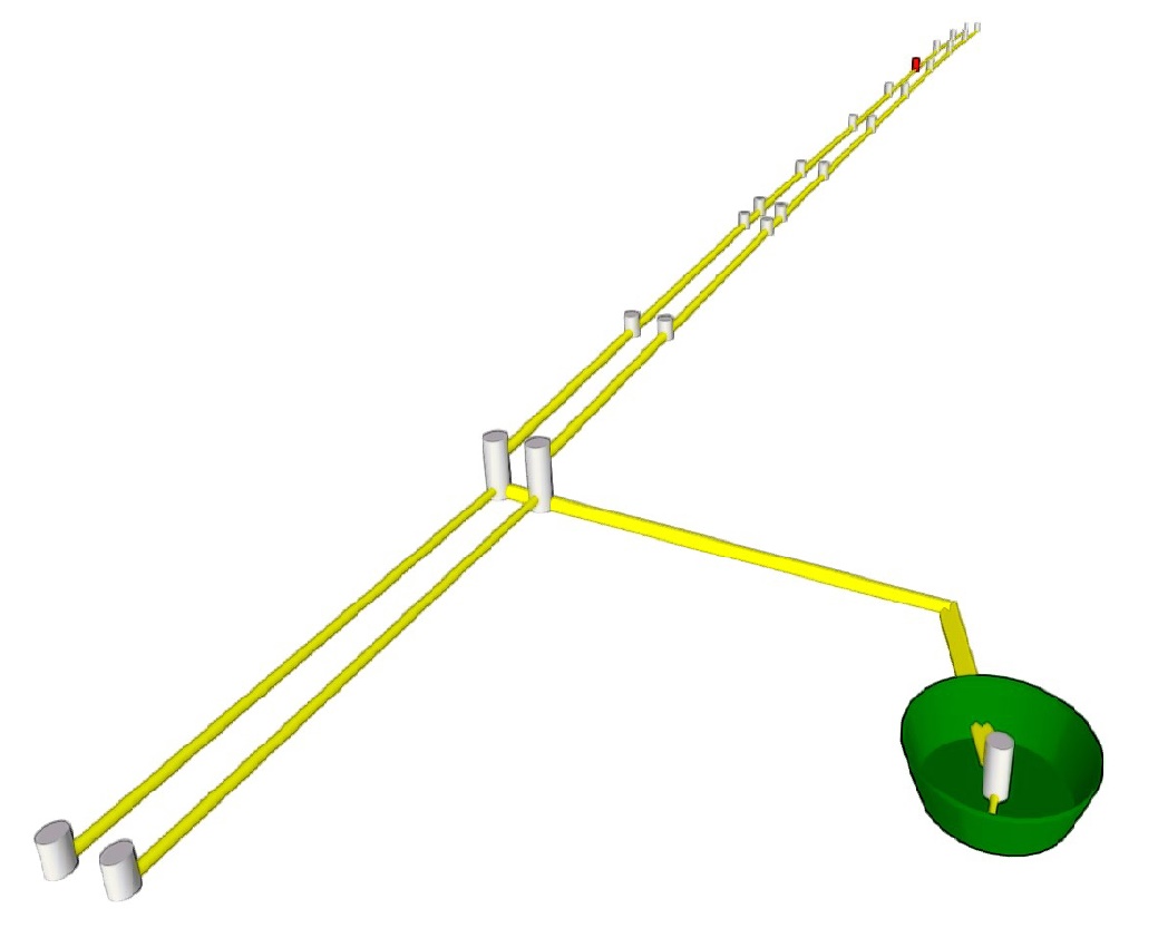
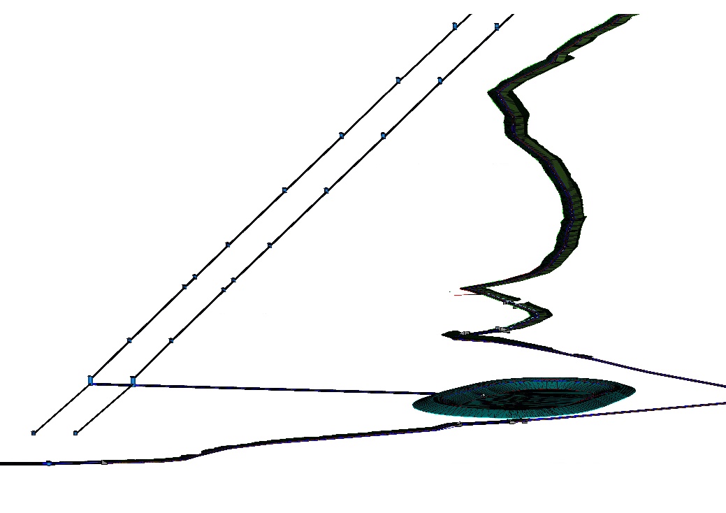
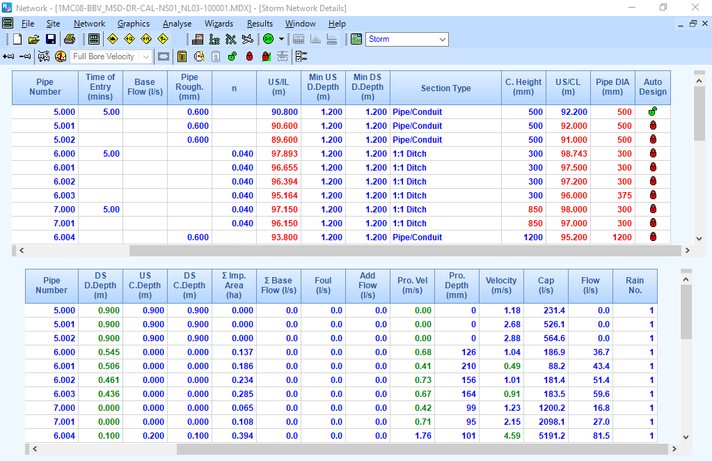
To address this, MMS has developed in-house design tools to link the two software packages together. The tools enable designers to convert from MD hydraulic models, an example of which is shown in Figure 1 into BIM models in Bentley ORD as per Figure 2 which includes the required attributes with minimal inputs form the designer.
Context
At the beginning of the project, MD hydraulic software was used as it allows BIM-compatible outputs such as Industry Foundation Classes (IFC) files and Surface water System SWS / DraWing File (DWF) files. BIM design in the project is carried out with Bentley OpenRoads Designer (ORD) software as it has the capabilities to achieve the LoMI required under the AD4. Initially, as a first approach, the geometry and the attributes available in MD were transferred separately and imported into ORD using inbuilt MD export tools. Attributes (some of which are available in MD, however, most are not), were manually added to the BIM. Initial tests took place in 2018 in order to apply an adapted, more holistic method: the transfer of MD data via excel files containing all the geometry (with a small number of attributes), via a ‘Model Builder’ module.
The full suite of attributes could then be automatically generated by analysing the drainage network in BIM and using a set predefined logic to generate and automatically update the BIM with all the required attributes.
It was then between September and December 2019 when the approach was fully developed, following calibration of the BIM process to ensure compliance with the BIM Execution Plan.
Overview
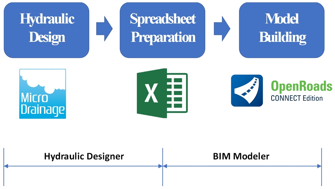
The main process of the tool developed and implemented in January 2020 is as shown in Figure 3.
How does the solution work?
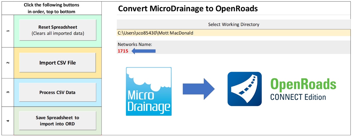
Converting the 3D model from the hydraulic model to the BIM model is the initial step. Bentley Open Roads Designer (ORD) package includes a tool that allows Comma-Separated Values (CSV) data to be imported and a BIM model is automatically created. This tool is called ‘Model Builder’. The first step is to export CSV data from the hydraulic model and rearrange it so it is in an order that ORD Model Builder can understand. This is achieved using VBA with an interface created as shown in Figure 4 below.
The tool has a list of commands to guide the user through the export process. The snapshot below (Figure 5) is just a small sample of the raw CSV data exported from MD.
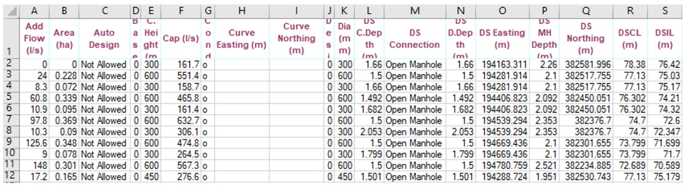
The tool then orders the data into various tabs in excel based on their feature definition. A feature definition is a type of chamber, pipe or headwall. For example, a shallow catchpit with a diameter of 900mm is called a CP3-900.
There are dozens of routines that are run on the CSV data. These include:
- Finding all the headwalls;
- Finding all the outfalls;
- Sorting chambers by their size and depth and assigning the correct feature definition;
- Deciding if a pipe is a Under Track Crossing (UTX), filter drain or carrier pipe. This is done by assessing the pipe roughness, labels added, depth and other factors;
- Stripping out conduits and nodes that are required for hydraulic modelling but not needed in the BIM model, such examples would be the conduit that connects the inlet and outlet headwall of a pond.
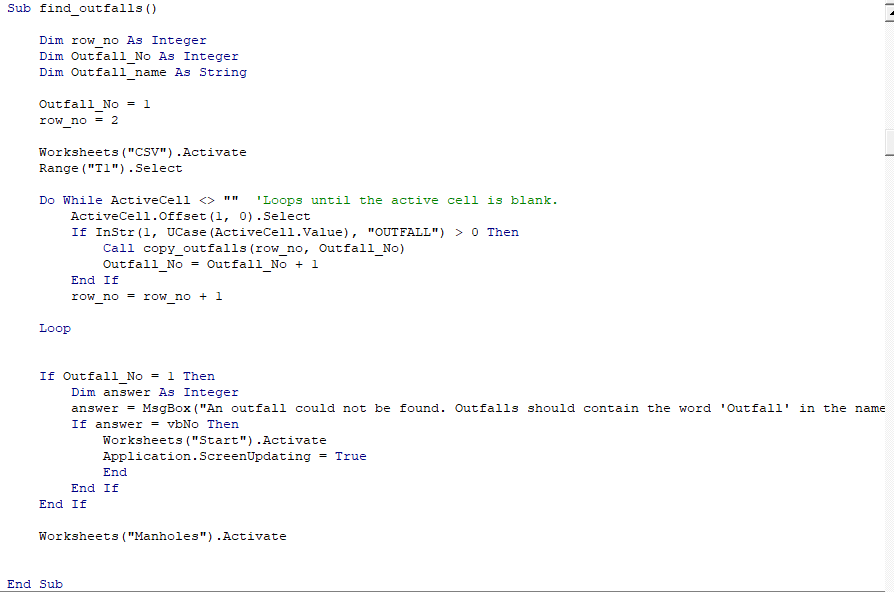
Figure 6 shows an example of a code that searches through all the rows in the CSV data and identifies all the outfalls. There are several thousand rows of code in total to achieve the above tasks.
The data below (Figure 7) are the post processed tab for chambers that meet the feature definition requirements for CP3-900. The data is ordered and titled in a way that it can be imported into ORD using Model Builder with no further processing required.
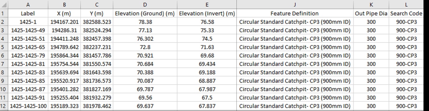
The above tool allows the transfer of 3D data into a BIM model in a reliable and efficient way. The next step is to generate and add the various attributes required under the AD4.
This is achieved by exporting CSV data from the BIM model, analysing with VBA to automatically make design decisions based on its geometry and asset naming and then using a VBA script in ORD to automatically add the attributes to the various assets such as chambers, pipes and headwalls.
This stage required a lot of upfront design decisions and clear design criteria that are linked to the project’s basis of drainage design [4]. As an example, if a chamber’s outgoing pipe is over a certain size a safety chain would be required in the chamber.
The VBA scripts have also been useful to apply more geometry data to pipes. For example, ORD cannot automatically label the pipe cover levels. With the tool, the relevant cover level can be selected from the upstream and downstream chamber and applied to the pipe. Similar enhancements have been carried out on chambers to automatically add incoming pipe sizes, numbers and invert levels. All this extra data makes the BIM model more useful and easier to review for the Designer and Contractor.
What has been required additionally?
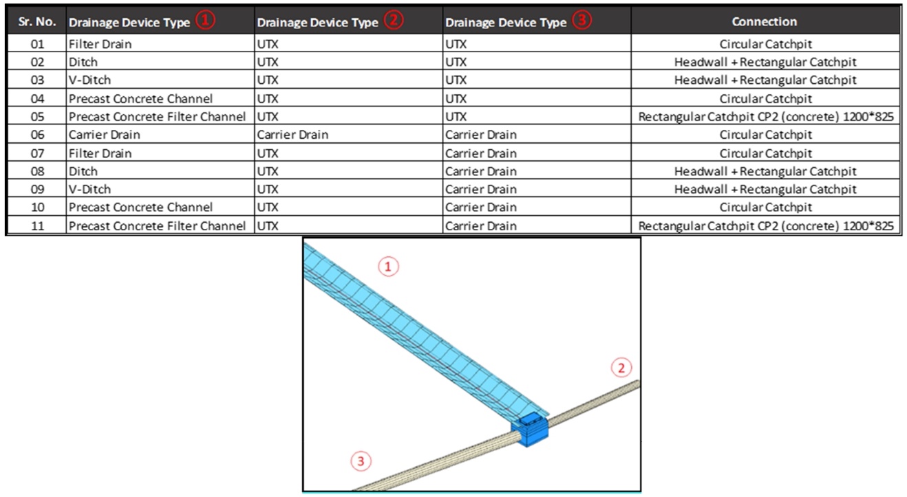
To achieve an acceptable performance of the tool, the team had to develop and specify an exhaustive library of design objects in the form of BIM feature definitions, as shown in Figure 8. This has also facilitated the consistency of drainage design across the different Area North packages.
Things to remember when using the tool
In order to categorise appropriately the different components in the drainage system, it needs to be correctly labelled in MD as shown in Figure 9. Pipe labels, pipe roughness, and pipe diameters are used by the VBA routine to determine the attributes of the asset. It is important, therefore, that the designers follow the guidance to ensure their hydraulic models can be correctly interpreted by the VBA routines.
After the import of CSV spreadsheet data, the VBA routine will sort the different conduits, manholes, etc. in tabs that will be used to generate an import file for ORD using Model Builder interface.
Model Builder as shown on Figure 10 can then be run. When running Model Builder, it is important to ensure that the mapping between your spreadsheet and ORD is correct so the conversion works as expected. Once a map is created, this map can be exported and shared with other users. A separate map is required for each feature definition, so it’s important that maps are checked to ensure that each feature definition has a fully populated map.

Conclusion and aspirations
The tool can be described as a minimal viable product to help achieve HS2 Ltd’s requirements in an efficient way. The tool has bridged the gap between software that can deliver drainage designs such as MicroDrainage and software that can deliver BIM deliverables such as Bentley OpenRoads.
The tool can accurately, efficiently and repeatedly convert the hydraulic (drainage design) files to BIM models and then fully attribute them in line with the HS2 AD4 requirements. This means that the hydraulic models are the ‘single source of truth’ (of data) and the designers only have to update the designs in one package. Other outputs such as drawings, BIM models or schedules are all derived by the modellers from that hydraulic model (via the tool developed and the BIM models).
This is possible with the MMS in-house tool that can convert the hydraulic model into a format that Bentley ORD Model Builder can understand and use the developed logic to generate all the attributes based on the BIM model.
There are more developments that can be undertaken to maximise the benefit. Some of the future aspirations include:
Customisable for other projects
The tool has been generated to meet the requirements in the HS2 Project. As such it has been built specifically for HS2 feature definitions and requirements. With further development, the tool could be customisable such that it can be used on a variety of projects to bring efficiencies to a wider audience.
Carrying out Self checks
This tool provides an improvement on quality assurance. For example, if an outfall is not found or a flow control does not have the required LOD, a warning is given.
This automatic check could be expanded to carry out comprehensive design checks such as:
- are the chambers large enough for the number and size of pipes connecting to them?
- are the gradients and velocities in pipes sufficient?
- are cover depth adequate?
- is the network deeper than it needs to be?
The above items can be checked in the drainage design model or with the software audit tool however, a project-specific automatic checking tool would provide a continuous improvement in quality assurance.
Carry out attributing and checks on other assets
To date, the tool has been used to build and attribute headwalls, pipes and chambers however, the transfer of 3D data only includes basic 3D information such as sizes, level coordinates and the feature definitions. The next part of the process is to apply non-hydraulic model related attributes. Since the import process above will be carried out multiple times, attributes such as backfill types or bed and surrounds need to be automatic and reliable.
Also, other assets within drainage such as ditches, ponds, gullies and cascades would also benefit from automatic attributing and checking.
Further to this, assets from other disciplines is also an avenue worth exploring in the future.
Acknowledgements
We thank all the drainage and BIM team in Area North for its contribution to the testing and subsequent improvement of the tool and process.
References
[1] Innovyze, (2016-2019). MicroDrainage user manual
[2] Bentley’s Technical Support Group, (2016-2019). Road and Site Design – Wikis
[3] HS2, HS2 (2016-2019). Asset Data Dictionary Definition Document (AD4)
[4] DJV/BBV, HS2 (2016-2019). Basis of Design Report – Drainage
Peer review
- Alex HulstonCAD Specification Manager, HS2 Ltd
- Richard AdamHead of Highways and Drainage Engineering, HS2 Ltd