An alternative approach to demolition screens at Regent’s Park Estate
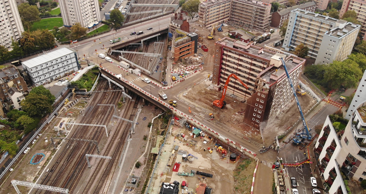
Regent’s Park Estate is situated within a densely populated area in the heart of Central London, bounded by a Transport for London red route to the East and Network Rail approaches into London Euston to the North East and residential properties and roads everywhere else. Traditional methods of demolition within this environment would normally have predicated a top-down demolition method enclosed by a scaffold encapsulation screen. However, in order to minimise the impact to local residents, the use of a demolition curtain was implemented, which acted as a shroud, complete with an integrated dust suppression system. This method of screening enabled demolition via a high-reach excavator of a size sufficient to utilise pulverisers, thus removing the impacts of percussive demolition. Other added benefits included reducing the duration of works by a third and removing 200 wagons from the local road network.
This paper will be of interest to demolition contractors working in busy urban areas.
- Written by
-
Thomas Cleary (CSjv/Costain)

- Resource type
- Resource type: Micro-report
Background and industry content
Mechanical demolition tends to fall into two categories; floor-by-floor with machines typically lifted in to position by support cranes; and off plan, utilising large enough machines, some with elongated arms, to reach the levels and areas required.
Both have their pros and cons, but tend to be governed by the local environment, namely space. A floor-by-floor method (Figure 1) tends to work very well in a built-up environment, like Central London, where space is at a premium and the machines can work within the footprint of the building being demolished. The buildings are encapsulated with scaffolding to protect the public from demolition debris and falling materials, often with covered walkways forming part of the encapsulation.
The downside of floor-by-floor demolition is that normally the machines that can be utilised with this method are too small to use non-percussive attachments. The use of breaker attachments is required, which in a built-up environment can cause disruption to residents, local businesses and passers-by.
An off-plan method (Figure 2) is the default position when space permits. It has fewer plant/pedestrian interfaces, little to no working at height and utilises larger machines that can demolish buildings much faster, with a massive reduction in noise and vibration.
The Enabling Works Contract (EWC) on the southern section (Area South) is part of High Speed Two (HS2) phase one which includes demolition of buildings within the wider Euston area, utility diversions, environmental and ecological monitoring and a programme of historic environment and archaeological activities, delivered by the Costain Skansja joint venture (CSjv).
CSjv’s default position for protecting the public within densely populated areas was a scaffold encapsulation. The challenge faced was combining an off-plan method with a protection screen, linked to some high-profile incidents at Reading1 and Coventry,2 the concern was how larger demolition machinery could transfer kinetic energy in to scaffolding or even inadvertently damage ties that would render a scaffold screen structurally unsound and lead to catastrophic failure.
So, the challenge: how to realise the benefits of off-plan demolition within a limited footprint whilst protecting neighbours.
Developing an alternative demolition screen solution
On EWC, CSjv were responsible for demolishing over 200 buildings over a 4-year period, with packages of works being released almost sequentially as buildings became available. With continuity of work force and the right culture, this enables a period of continuous learning and improvements, rather than knowledge gained being lost as enabling work leads immediately to permanent works. Whilst this paper is about the work carried out at Regent’s Park Estate, the concept of the idea appeared about 18 months previously whilst demolishing a petrol station canopy on the other side of Hampstead Road. This approach was further developed to provide a much larger solution to enable the buildings in Regent’s Park Estate to be demolished.
Demolition curtain – the first iteration
The requirement was to dismantle/demolish a former filling station canopy as part of the UCL demolition works. The canopy extent was in line with site hoarding, with busy footpath and bus stop adjacent to the area (Figure 3).
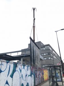
It was known that the bus stop was used by a number of vulnerable residents from buildings belonging to the London Borough of Camden and so, the supplier was set the challenge of coming up with a protective solution that did not require closure of the footpath or bus stop, but still enabled the safe demolition of the canopy.
The specialist subcontractor, John F Hunt, suggested using a demolition curtain, suspended from a mobile crane. It consisted of rubber Kevlar sheets fixed to a long beam section, providing a physical barrier between the works and the general public. In essence, it created a continuation of the hoarding to an approximate height of 6m, allowing works at height to continue safely.
A lessons learnt workshop was run with all stakeholders and a plan was formulated for how to implement the demolition curtain on the Regent’s Park Estate demolition.
Regent’s Park Estate background
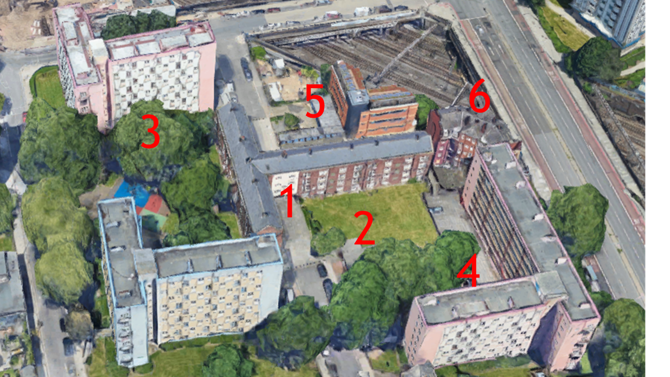
Possession of Regent’s Park Estate (Figure 4) commenced in February 2019. The estate consisted of 6 buildings;
- Ainsdale
- Old Tenants Hall
- Eskdale
- Silverdale
- Granby House
- Stalbridge house
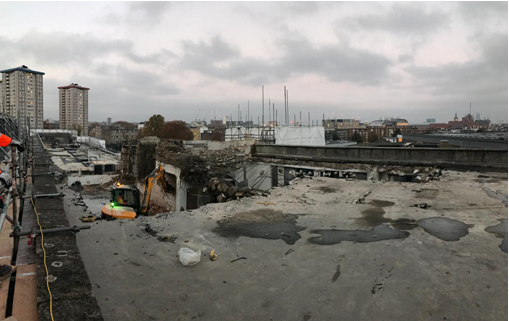
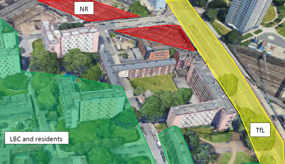
The initial proposal developed was to wrap each building in scaffolding, except Old Tenant’s Hall (2) and the internal half of Ainsdale, and demolish floor-by-floor. This decision was taken because of the close proximity to Hampstead Road, a TfL Red Route, Network Rail’s Assets and London Borough of Camden’s (LBC) roads and residents (Figure 5).
Two buildings were targeted within the set of six, to see if the lessons learnt from the petrol station could be used to provide an alternative screen solution. These buildings were Eskdale (3) and Silverdale (4).
Developing the solution
Originally, both Eskdale (9 floors) and Silverdale (7 floors) were due to be encapsulated in scaffolding and demolished floor-by-floor. The scaffolding for each building was programmed to take 8 weeks each, requiring nearly 300 lorry movements through the local estate to deliver scaffold materials to and from site.
Using the revised method also required an attendant crane in position to lower machines down as each floor progressed (Figure 6). Eight tons was the maximum machine size and could only demolish the structure using breaker attachments. The planned duration for Silverdale and Eskdale demolition was 12 weeks, on top of the 8 weeks scaffolding duration.
The key constraints under consideration were:
- Surrounding Stakeholders
- Air quality – in terms of dust from demolition but also through carbon emissions
- Preventing uncontrolled collapse or a failure in the temporary works/structure
- Minimising of noise and vibration
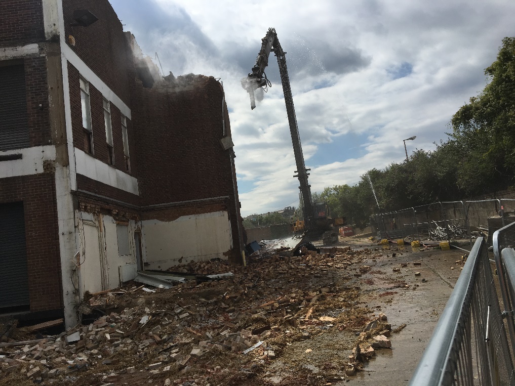
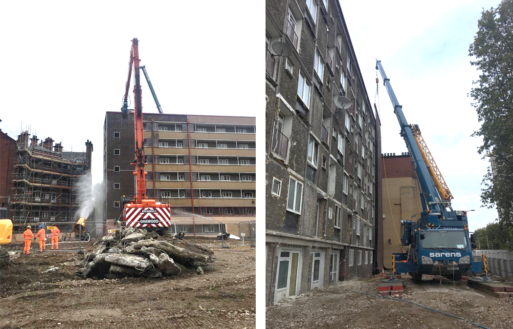
The challenge was set to the team, this time alongside the specialist demolition supplier Clifford Devlin, as to whether the scaffold encapsulation screen could be replaced with the demolition curtain used previously and therefore utilise a long reach machine and capture the associated benefits.
Following some research, examples were found in Salford, Manchester and Germany, which reflected the built-up environment surrounding the RPE buildings. There was confidence that a demolition solution could be delivered that combined a demolition curtain with a long reach machine, but engagement with all interested stakeholders was needed, specifically the community and near neighbours. A 3D model (Figure 7) was developed to better explain and communicate to non-technical members of the team and the community stakeholders, how the solution was going to work.
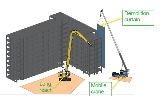
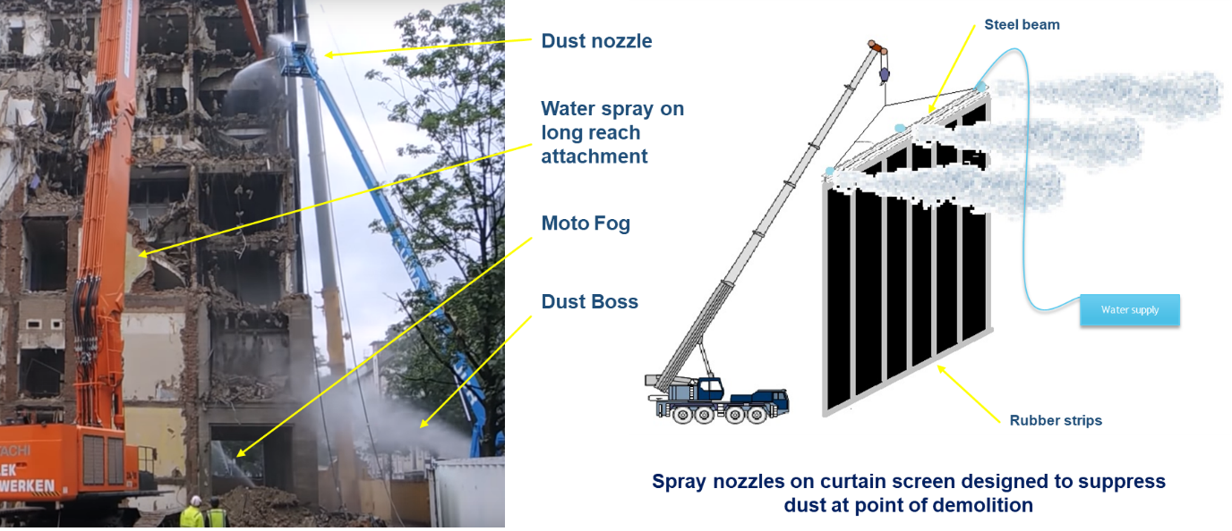
The general plan was that a mobile crane would hang a curtain against the outside face of the building being demolished. The idea was to provide protection from flying debris at the point of demolition, but rather than trying to cover the whole building, it was a mobile system so would move as the demolition progressed. An exclusion zone would be created at the bottom with skips/kentledge placed to control the curtain and therefore debris from escaping. The long reach would sit on the inside face of the building and in a controlled sequence, demolish the building. There would be constant communication between the Demolition Manager, the Long Reach Team and the Mobile Crane Team through headsets to control the movement of the long reach and the curtain in tandem and also communicate any changes that may have occurred that needed addressing.
The potential benefits of this combined long-reach and demolition curtain solution were;
- Health, Safety and Environment:
- Reduced falls from height due to no scaffold erection, dismantling and fewer wagons to site importing material
- No operatives required at the face of demolition i.e. reduced plant and pedestrian interface
- Long reach attachment pulverisers therefore reduced noise and vibrations levels
- Uncontrolled Collapse or Temporary Works failure
- Removal of scaffolding meaning no structural continuation between the screen and the building being demolished.
- Reduction in the amount of temporary works e.g. no propping required throughout floor-by-floor propping
There were also some key considerations that arose as a result of developing this solution, namely:
- Provide protection from dust and falling materials/flying debris
- Increase in at source dust levels
- Exclusion zone needs to be managed without scaffold encapsulation
- Additional road and footpath closures required to meet zone needs
- Location of long-reach and crane chosen to reduce impact of any failure
- Designed wind working limit for curtain and if it would allow productive working
The curtain design
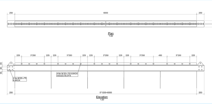
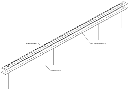
The design of the curtain consisted of a steel beam; of six metres in length and a total weight of 360kg (Figure 8 and 9); screen material of four strips of kevlar flooring belt, length 25m, width 1500mm, thickness 25mm and with a total weight when combined of 5400kg.
Bespoke dust suppression
It was known that with pulverising there would be a greater creation of dust at the point of demolition compared to breaking, so a solution had to be found to provide that. A bespoke inbuilt dust suppression system was designed to tackle dust arisings from the pulverising at the source. This was combined with other dust suppression systems including on the long-reach attachment and dust cannons (Figure 10).
Treating the curtain as a flag
The design of the curtain and it passing as a workable solution ended up hinging on how the curtain and the crane would behave under wind loading. There were 3 main issues:
- The curtain being tied to the kentledge/skips to prevent escape of arisings
- Drag Coefficient being assumed for a rigid sheet
- Exposed surface area of the curtain
Table 1 shows how each design issue was considered with respect to wind loading and the proposed solution to deal with that.
| Design Issue | Effect on Wind Loading | Proposed Solution |
|---|---|---|
|
Curtain tied to kentledge at GL to capture risings |
Mechanism creates a sail effect when pinned at both at jib and GL. Higher effective wind loading. |
Curtain to have free end Enables proportion of wind loading to pass through |
|
Drag coefficient – Rigid Sheet |
This drag coefficient for curtain increases effective wind loading.3 |
Consider curtain as free flag and use associated formula.4 Reduced effective wind loading Cw 2.0 -> 0.27 |
|
Full curtain surface area considered as exposed during demolition |
Allowable working wind speed reduced if consider full curtain exposure. Max Wind speed = 4.0m/s |
Residual Risk- Curtain tight to building to transfer wind loading to structure Surface area – 1m above and 1m across point of demolition Max Wind speed = 7.12m/s |
Working these through to achieve a design that allowed a Max Wind Speed of 7.12m/s (15.9mph) was a massive result, even at the last step there were reservations that it could actually work under a permissible Max Wind Speed of 4.0m/s (8.9mph).
Long reach machine and crane
Now that there was a screen solution that did not have structural continuity into the building, there was assurance that much larger machines could be used, and the concerns highlighted previously could be avoided as separation provided.
A 75-tonne excavator was utilised with a long reach arm of 33m in length. This allowed pulverising attachments equivalent to a 20-tonne machine, meaning that it was possible to achieve the goal of using non-percussive demolition techniques, thereby hugely reducing the impact of noise and vibration on the neighbours.
Alongside this sat a 100-tonne mobile service crane. This provided far more scope to move the curtain and reduced the number of set ups required.
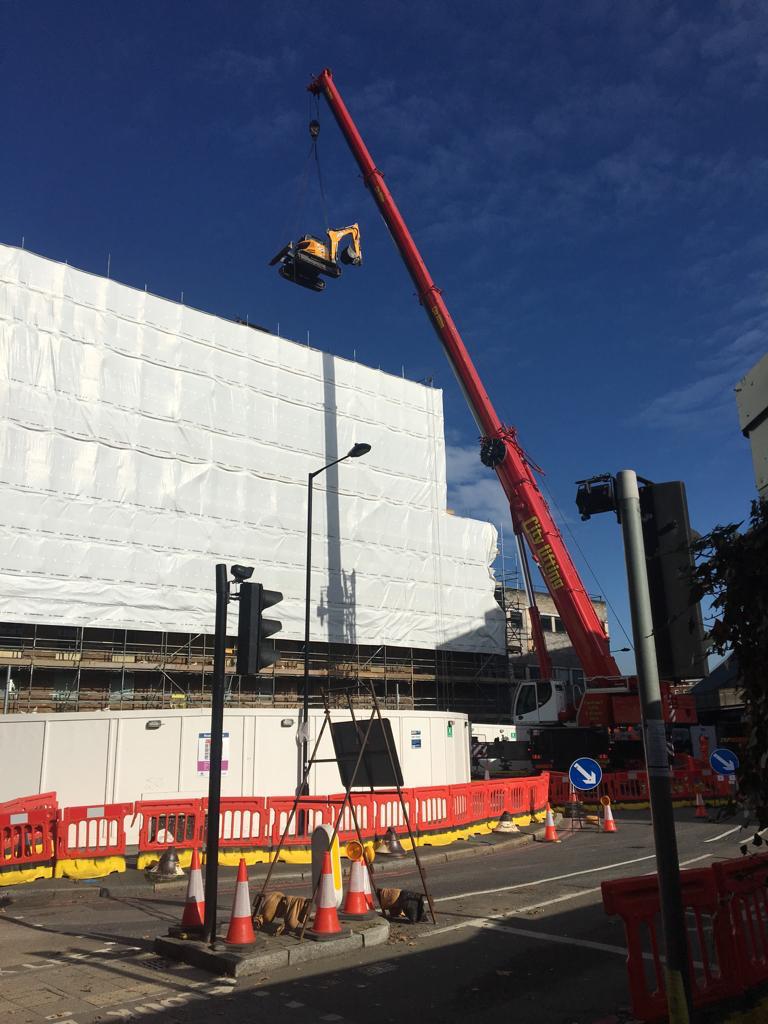
Demolition test run
Both the long-reach machines and the curtains were delivered to site a week early so that tests could be carried out on the system (Figure 11). The test runs allowed CSjv and Clifford Devlin to realise the following improvements needed to be made:
- The water pressure was not sufficient for the dust suppression required at the top of the curtain at its highest point.
- Dual exclusion zones needed to be set up, restricted access (only demolition personnel could enter) and full demolition zones (no access at all)
- Communication worked best thought the Demolition Manager controlling all gangs and centrally co-ordinating
- Understanding the time taken for raising and lowering the curtain
- Enabling the site team to understand their working environment and tweak space and boundaries.
Lessons learned and successes
What worked well
Using the demolition curtain on Eskdale and Silverdale reduced the requirement to encapsulate the buildings with scaffolding, this saved approximately 200 vehicle movements during the Regents Park Estate Demolitions. The resultant reduction in vehicle movements saved approximately four tons of carbon.
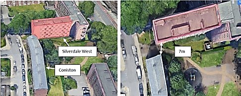
The west wing of Silverdale had to be demolished using a traditional floor by floor method due to the proximity of Coniston (less than seven metres) and not being able to obtain consents through the London Borough of Camden (Figure 13). This meant that there was an identical comparator to assess the two different schemes.
Using the demolition curtain with a larger long-reach excavator led to the programme being cut by over 50% when compared to floor-by-floor and therefore, a reduction in the disruption caused to local residents. The minimal space on the floor plate combined with thinner balcony slabs than shown on the drawings, meant that working on the floor plate was exceptionally congested and slow going.
Perhaps the biggest benefit was that it dramatically reduced the need for percussive breaking, reducing noise and vibration impacts. Zero noise complaints were received from local residents regarding the long-reach methodology, but noise readings taken at Coniston during the floor-by-floor method exceeded those recorded through the long-reach.
There was a significant reduction in the amount of risk hours worked associated with working at height:
- Silverdale: approximately 18,000 hours of scaffolding
- Eskdale: approximately 46,000 hours of scaffolding
- Removed the working at height from unloading and loading the scaffold wagons.
- Removed well holes required to transport building debris and plant during floor-by-floor demolition, thereby eliminated leading edges.
- Eliminated the need for working platforms required for lifting or dismantling purposes for beam sections or structural elements.
There was a betterment in reducing the risk of uncontrolled collapse;
- Curtain and containers provide robust protection from demolition debris, without the need for a structural tie to the building.
- Removal of chain reaction collapses; one failure does not mandate the failure of the entire system.
- Less dependency on pre-construction information and structural surveys; no requirement to make design assumptions on incomplete information.
- Ability to use larger machines, with higher capacity attachments, without concern of accidental impact to the structural integrity of the protection system. This would not be feasible with a tied in scaffold.
What didn’t work so well
- Lack of pre-construction information at the time of designing the solution meant that there was a lot of unknown asbestos in buildings, which pushed the start date back for non-structural, and ultimately structural, demolition.
- Once access to the site had been given, it was immediately found that all the buildings were/had to be clad in rockwool, which was to ensure material segregation and maintain high levels of recycling (crushing on site to create 6F2/5). This was a hugely time-consuming operation.
- A lesson learned to purchase extra mats, so that outrigger locations could be pre- set up prior to moving the crane, this saved 1-2 days each time.
- Testing overall site water pressures beforehand. The dust suppression combined system required up to nine litres per second across the whole site, and a minimum pressure of 30psi (2 bar). A fire hydrant supply had to be applied for and the water supply system supplemented with tanks for each water cannon and pumps across the site.
- There were a number of challenges from London Borough of Camden on the dust arising from site, this despite the large amount of equipment deployed. An independent peer review carried out stated “they have carried out beyond reasonably practicable dust suppression that they are leading by example and are producing best practice suppression techniques.”6
- It took a while to get there, but the best dust suppression solution was a person in a basket of a Mobile Elevated Working Platform (MEWP) holding a hose and spraying where required.
Recommendations
- Utilise an open topped skip or “bin” to drop the curtain into when not being used, this allows it to be moved fairly easily in the case of high winds.
- Explore reducing the exclusion zones. Footpaths and roads were closed outside of the demolition exclusion zone, but it was realised there was very little need to do this. Due to the nature of pulverising, the only energy is transferred by potential to kinetic from the height of the building with falling debris, this can easily be withheld by hoarding.
- Develop and design the water system and dust suppression well in advance, running out, especially in a contentious environment brings the programme to a halt.
Acknowledgements
- The Euston Approaches Demolitions Team; Dan Brown, Era Shah, Joe Jelfs, George Horsley, Hanna Toorabally, Ricky Prett
- The CSjv Engineering Team; Jeff Mahony, Stefano Quintaville, Adam Hope
- Clifford Devlin
- John F Hunt
References
- Reading scaffolding collapse investigation begins BBC News.
- HSE Media Centre. Link provided but removed from website
- BS 7121-1:2016 Code of Practice for Safe Use of Cranes Table D.3
- BS EN 1991-1-4 Eurocode 1: Action on Structures – Part 1-4 Table 7.15
- BS 6187:2011 Code of Practice for Full and Partial Demolition
- HS2 – CAMDEN DEMOLITION AND DUST PROCESS REVIEW C&D Demolition Consultants Ltd.