Reducing the impact of diverting a 42-inch water main
High Speed Two (HS2) intersects utility company networks throughout its length. Utility works are an important factor when planning and carrying out infrastructure projects, and similar diversionary works are likely to be required during Phase Two of HS2. This paper seeks to share examples of good practice and lessons learnt in the design and construction of the diversion that are particularly relevant to reducing the impact of major utility works in urban environments. One of the key developments explored in this paper is the use of a boltless ductile iron pipe system, which saved hundreds of hours of confined space working and ensured smaller excavations and work sites could be used, minimising the impact of the works on stakeholders. The use of this system on this project was a first for TWUL.

Introduction
In London, a number of highly strategic clean water trunk mains and sewers owned by Thames Water Utilities Ltd (TWUL) will be affected by the construction of High Speed Two (HS2). At Euston Station, an existing 42” diameter cast iron trunk main (the 42” main) directly clashes with the new high-speed platforms, and further north the same main is at risk of failure by the construction of the new tunnels and tunnel portal within the Station’s approach cutting generating unacceptable settlements.
The pipeline, built in 1925, is critical to the supply of water to a population of approximately 225,000 in Central London, including areas such as Covent Garden, Kings Cross, Camden and Islington. Therefore, the works to divert the main were prioritised by HS2 and TWUL, and construction of the new main began shortly after the hybrid Bill for Phase One of HS2 gained Royal Assent.
HS2’s proposed construction works
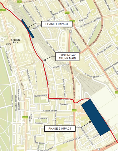
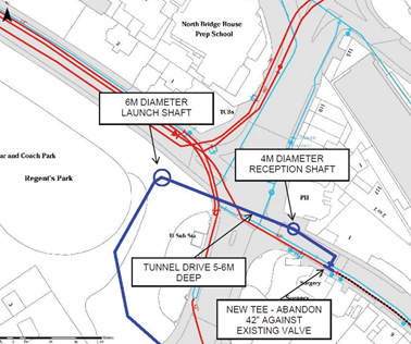
There are two separate sections of the HS2’s main civil works in Camden which have an impact on the existing 42” main. The impact of these separate sections occurs with a significant delay between them. The works in the Station’s approach cutting will begin first and include but are not limited to; the construction of the Euston tunnel portal; construction of the ‘crossover tunnels’ between the Euston Cavern and the tunnel portal; and associated works such as the installation of ground anchors within the retaining wall adjoining Park Village East and also containing the 42” main. Therefore, the diversion of the 42” main has been split in to two separate phases which reflect HS2’s programme priorities, these phases can be seen in Figure 1. This paper focuses on Phase 1 but also gives a brief description of Phase 2.
As described above, the purpose of the Phase 1 diversion is to divert the 42” main out of Park Village East. It was agreed that the first phase would be delivered directly by TWUL and their AMP6 alliance joint venture partner’s Skanska, MWH (now Stantec) and Balfour Beatty. The second phase, involving the diversion of the main out of Cardington Street and into a dedicated utility corridor, would be planned and delivered by HS2’s Contractor at Euston Station.
Phase 1 diversion route
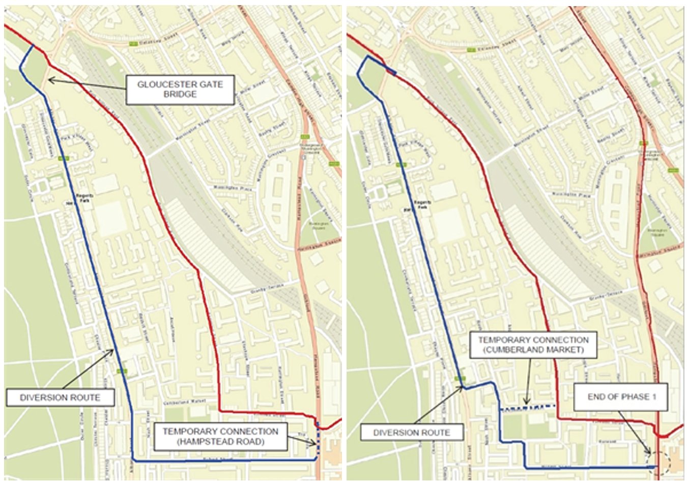
HS2’s hybrid Bill submission to Parliament in 2013 included a high-level overview of how the new railway would be built, including major utility works such as the Euston 42” main diversion. Figure 2 below shows the proposed diversion route from Prince Albert Road, through the London Zoo car park, Albany Street and Robert Street. Figure 2 below also shows an optimised diversion route which reflects the as-built diversion. Two key differences can be seen: the northern connection at Park Village East rather than Prince Albert Road, and the temporary connection at Cumberland Market rather than Hampstead Road. In total, Phase 1 consists of approximately 1.5km of new pipeline.
Northern connection
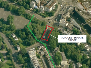
A number of challenges were identified with the connection on to the existing 42” main at Prince Albert Road. The diversion route had to avoid Gloucester Gate Bridge, which is a Grade II listed structure with a shallow deck incapable of containing a large diameter main. This meant the diversion had to be routed through the Regents Park and London Zoo car park. The car park and the land either of side of Gloucester Gate Bridge formed part of the now infilled Cumberland Market Arm of the Regents Canal, this can be seen in Figure 3. The canal infill meant the ground conditions in the area were far from ideal for the construction of a new strategic trunk main.
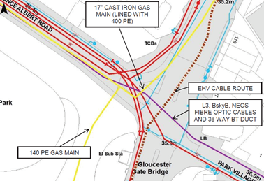
Other constraints include major existing utilities in the surrounding roads, including a 17” gas main, a 36-way BT duct, oil-filled extra high voltage cables, a large brick egg sewer and a 36” water main branch from the 42” main. The location of these services is indicatively shown in Figure 4. To install a connection in Prince Albert Road, several major secondary diversions would be required with the associated road traffic disruption and extended utility network outage requirements.
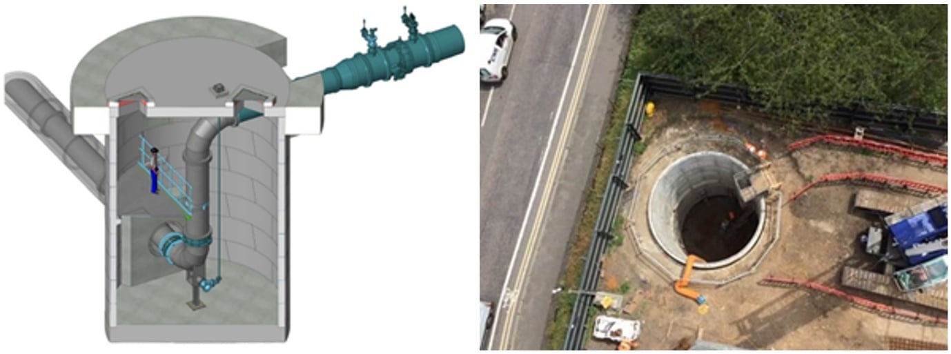
The alternative and adopted solution involved tunnelling from the Zoo car park to Park Village East, avoiding the major utilities in Prince Albert Road, avoiding a major road closure in the Prince Albert Road and Parkway junction, and making use of an existing valve and thrust block to make the connection. This solution therefore greatly reduced the duration of the works and the impact on the road network. This is shown in Figure 5. A 3D model of the launch shaft, and a picture of the same shaft during construction is shown in Figure 6.
Southern connection
The biggest challenge in the construction of the southern connection in Cumberland Market was the configuration of the new thrust block needed to resist the forces through the ‘tee’ connection in to the existing main. The 42” main operates at a pressure of up to 5 bar, generating a force of approximately 500kN. If unrestrained, the joints in the old cast iron pipeline would be likely to dislocate and result in a burst.
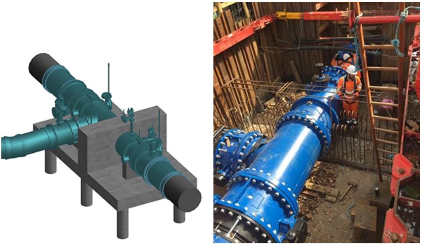
To minimise the number of secondary utilities impacted, the footprint of the thrust block was reduced through the development of a piled solution. Whilst the size of the thrust block was significantly reduced versus a traditional ‘mass concrete’ thrust block, the construction of the piles around the existing main required a series of network isolations to safely construct the thrust block. A 3D model of the southern connection is shown in Figure 7. Figure 7 also shows the southern connection in construction, with the new pipeline and reinforcing bars installed.
Pipeline specification
To further mitigate the impacts of constructing a 1.5km diversion in the highway in central London, a change from the ‘business as usual’ approach to pipe laying was investigated. The ‘usual’ approach for constructing a large diameter water main pipeline requires bolts to be installed around the full circumference of the pipe joint. This involves large excavations and many hours of confined space working to fix each joint. Over 1.5km, a huge number of joints are required.
To reduce both the size of the excavations and the amount of confined space working required to construct the diverted main, the designers proposed a DN1000 ductile iron pipeline, using an innovate boltless pipe jointing system [1]. A technical waiver was required, as this type of pipeline had not been used before by Thames Water.
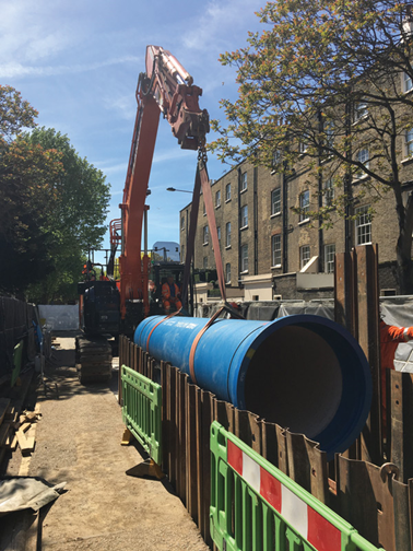
By reducing the size of the excavations, the impact on the road network was reduced so that closures were kept to a minimum and productivity increased, which in turn reduced the length of the overall programme. Figure 8 demonstrates the reduced size of excavation possible by using this innovation.
Challenges during construction
Despite an extensive survey programme during the detailed design stage, consisting of ground penetrating radar surveys and trial trenching, uncharted utilities were regularly encountered during the works. Uncharted utilities present a significant health and safety and schedule risk for any project in an urban environment involving street works.
Schedule delays were minimised when uncharted utilities were encountered through collaborative working between the client team, the contractors, sub-contractors, other utility company and the local authority, to quickly identify ownership of any uncharted services, and in undertaking re-design and/or protection works to ensure the diversion could be safely constructed around any uncharted services. Where there was not a direct clash between the uncharted services and the new pipeline, a change to the temporary works was usually sufficient to minimise any delays and to protect the uncharted service. Where there were direct clashes, a decision was required to agree whether the uncharted service should be moved or whether the design for the new pipeline should be modified.
Each pipe was 7m in length. In many areas, the highway was found to be so densely populated with utility services that an extended excavation was needed to find a gap sufficiently long to safely lower the 7m long pipes into position. Figure 4 provides a good example of the density of utilities contained in a typical London highway. This was largely anticipated proving the value of the detailed survey works.
Working with stakeholders
The planning and coordination of the works was a major undertaking to ensure the success of this project. In constructing the diversion over 1.5km of the highway network, the project faced a huge number of interfaces. This included but was not limited to; HS2’s Enabling Works Contractor undertaking other utility diversion and demolition works; other utility companies carrying out their own works which were unrelated to HS2; housing developers in the Regents Park Estate; local businesses; nearby schools; and a military barracks. HS2 has successfully instigated forums such as the Traffic Liaison Group, which play a key role in fostering a collaborative approach to the coordination of street works across local authority areas to minimise impacts on the road network.
The diversion of the main through the London Zoo car park also provided a unique challenge to safeguard the last remaining breeding hedgehog population in a central London park. Thames Water, HS2 and the Royal Parks organisation worked closely throughout the project to ensure that hedgehogs were protected.
Conclusion
The diversion of the Euston 42” water main has played an important role in enabling the main HS2 civils works in the Euston approach to begin. Despite the many complexities involved in a project of this type and scale, a combination of careful management and decision making during the design, specification, and construction stages has minimised the impact of this project on the communities and stakeholders impacted by HS2.
The use of the boltless pipe jointing system was an important innovation to minimise the impact of the project and to also lower costs by enhancing the productivity of the project. The use of tunnelling as an alternative to open-cut construction near the northern connection, and the use of piles as an alternative to mass concrete as a thrust block at the southern connection, also had significant positive impacts in reducing the impact to other stakeholders.
In replacing a 95-year-old trunk main with a new pipeline, this project has also played an important role in modernising the water network to ensure the reliability of supply of clean water to north-Central London, in areas such as Covent Garden, Kings Cross, Camden and Islington.
Acknowledgements
With thanks to David Meacham and Laura Edwards, Thames Water Utilities Ltd, and Iain Shorthouse, HS2 Ltd, for their assistance in drafting this paper.
The author would like to acknowledge HS2, TWUL, and the Skanska MWH (Stantec) Balfour Beatty joint venture for the provision of many of the images in this paper.
References
[1] Saint Gobain Pam – Universal VE Joint Technology, Accessed 6 October 2020
Notation
| Abbreviation | Title |
|---|---|
|
AMP6 |
Asset Management Period 6 (the 2015-2020 Ofwat price control period) |
|
DN |
Diameter Nominal (internal diameter) |
|
km |
Kilometre |
|
kN |
Kilonewton |
|
m |
Metre |
Peer review
- Colin Rawlings, Lead Tunnel EngineerHS2 Ltd