Safe borehole casings reductions for instrumentation and monitoring installed in cuttings
This paper is presented as part of the works to deliver the Main Works Civils Contract (MWCC) for the central section of High Speed Two (HS2) Phase One which includes the North Portal Chiltern Tunnels to Brackley and Brackley to South Portal of Long Itchington Wood Green Tunnel, being delivered by the EFKB Integrated Project Team.
The objective of this document is to describe the good practice implemented on site during the construction of instrumentation and monitoring boreholes during pre-construction phase of HS2 mainline cuttings. It is aimed at geotechnical monitoring professionals involved in drilling and installing in-ground instrumentation in areas that will be excavated, therefore requiring the instrumentation casing to be progressively reduced as the excavation progresses.
This paper is meant to share a good practice observed on site and hopefully ensure this becomes the new standard way of installing this type of instrumentation in the future.
Background and industry context
Installing instrumentation to measure movements or other geotechnical properties of the ground is a key part of the construction process, to verify the ground model, ensuring safety of the asset and providing valuable data on actual behaviour of the geotechnical formations present on site.
To install the instrumentation usually requires drilling a borehole and placing a protective casing inside which contains the instrument or provides the necessary support to perform manual readings using a probe. To allow sufficient space to place the casing, drilling to achieve a larger borehole diameter than the instrument casing is normally required. This results in the creation of a void space normally referred to as the “borehole annulus”. The space is filled with a mixture of water, cement and bentonite in proportions which are meant to be chosen in such a way to mimic, as close as possible, the mechanical behaviour of the surrounding material. This cementitious mixture is normally referred to as “grout” and usually requires up to a month to fully cure and reach peak compressive strength.
In the case of boreholes drilled and grouted within cuttings this is the normal practice and once the casing is sufficiently exposed, the hardened grout around it needs to be carefully stripped so that the casing can be cut down. This procedure is required to be done at a sufficiently high frequency to avoid the excavation to progress too far and expose too much of the casing and grout.
In the context of the central sections of HS2 where EKFB is operating, this is a very common occurrence and a substantial number of boreholes in these conditions need to be drilled in order to allow construction to proceed.
Approach
Due to the quick pace of the excavation progress of the cutting, it can happen that a long section (over 1.5m long) of the instrument casing is left exposed. This can lead to problems related to breakages of the casing, potential instrumentation damage and health and safety risks for the operatives working nearby the boreholes. The risk arises from the elasticity of the instrumentation casing, which can knock back rapidly once the weight is released, potentially hitting operatives and/or project small bits of grout in the nearby area. This is because grout can stick to the instrument casing as shown in Figure 1 below:
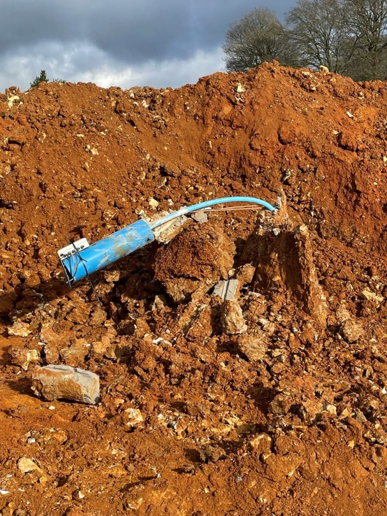
The example in Figure 1 shows a small piezometric casing which is also weighed down by the blue steel cover and the datalogging unit on top but a similar effect can be observed also on larger diameter casings such as the ones used for inclinometers or extensometers caused only by the weight of the grout attached to the top of the casing.
Removing the grout when the instrument casing is bent under some weight is a delicate operation that involves a certain amount of risk, which would be preferable to be avoided if possible.
The solution to this problem was presented to EKFB by one of its monitoring subcontractors via their submission of the work package plan (WPP) document[1] required before any works can take place. They had used it successfully previously. It consists of filling the borehole annulus with grout only until the final expected elevation of the cutting in the area and completes the remaining part that will be excavated only with sand.
This simple adjustment to the installation procedure avoids any risks involved with the instrument casing reductions as the sand will not stick to the casing and will be excavated easily, leaving the casing exposed and ready to be reduced safely.
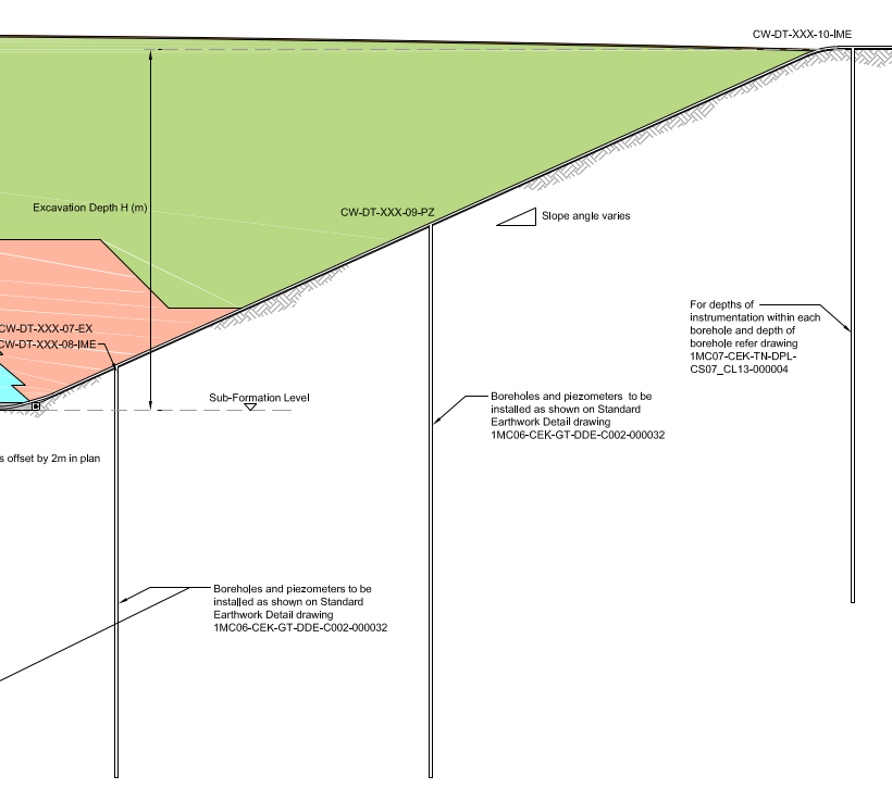
Note – The yellow sections show the part of the boreholes to be filled with grout (water, cement and bentonite mixture), the orange section is the part to be filled with sand.
Detail of the installation procedure used is (extracted from WPP):
1.1.1.4.1 Installation of Vibrating Wire Piezometer (VWP, fully grouted method)
▪ All sensors will be ‘sat’ in deionised water for the length of time that is specified by the manufacturer
▪ All materials and sensor depths shall be installed into the borehole as agreed for each specific installation by the nominated installation designer and by written instruction in advance of the installation. Carry out a P-IAT.
▪ Using the installation instruction, the materials shall be prepared and checked, and sensors will have “Site Zero” readings taken from them.
▪ Before inserting anything into the borehole, the borehole will be dipped with a water probe to ascertain where the water level and the base level of the borehole is. This information will be used to assemble the VWP sensor array.
▪ The sensors will be attached segments of 19mm pipework and assembled in place by use of the rig clamps or a stand-alone clamp set, and duct taped to the pipework in the tip-up configuration. The next segment of 19mm pipework will then be screwed on to the assembly and any cables will be secured to the pipework in a manner that keeps them out of the way of clamp jaws.
▪ The pipework shall be lowered into the borehole, either by hand, or with the assistance of the winch and hand clamps for deep boreholes.
▪ Ensure good manual handling techniques are always used including team lifts. Use mechanical aids where necessary.
▪ Steps will be repeated until the entire array is in the borehole and is left suspended in place for a plumb install.
▪ Once in the borehole, the sensors will all have readings pulled from them to ensure no damage to the units or wires during assembly and emplacement.
▪ Using the sacrificial 19mm pipe, grout will be pumped down into the borehole so that all sensors are covered. Once grouted to formation level (excavation level), the borehole will then be filled in with sands and gravels in preparation of excavations.
▪ All materials will be added to the borehole with regular depth checking using a weighted tape and pumped volumes will be compared to the calculated hole volume to fill; please note depth checking of liquid grout zones can only be carried out following an initial set/partial set period and is not able to be completed whilst in a liquid state.
▪ The grout mix used will be in accordance with the DMP.
▪ There is to be a sealing plug at least 1m above the filter pack to confine the intake zone. For multi-level piezometer, there will also be a sealing plug above and below each measuring level.
Outcomes
Since the WPP describing this measure was submitted to EKFB, it has become a standard requirement to install in-ground instrumentation within cuttings using sand for the part that will be excavated.
Limitations of the methodology are:
- that the time of grouting needs to be carefully managed to avoid standing time as the grout will need some time to cure sufficiently to allow sand to be placed on top without sinking in the mixture.
- It is also recommended to fill with grout above the final excavation level to compensate for any grout shrinkage that will happen during curing.
This procedure is applicable to all in-ground instrumentation to be installed within areas that will be excavated during the progress of the construction works.
This has effectively stopped any issues related with grout and casing reductions, with no incidents on site since introducing this method, making it easier and safer for both the construction team and the instrumentation and monitoring subcontractors to carry out this operation.
Learnings and recommendations
Instrumentation casing reductions continues to be an operation requiring close coordination between the construction team and the instrumentation and monitoring subcontractor to avoid instrument damage but implementing this simple change makes the process less time dependent and less risky. Using sand to fill the annulus doesn’t seem to have any negative effects on the performance of the instruments and it reduces the risk of damaging the equipment as it doesn’t require to break any grout.
It is therefore recommended that this becomes industry standard practice.
Conclusion
This learning legacy is about making a simple adjustment when installing in-ground instrumentation in areas that will be excavated that can improve safety and simplify the process of reduction of the casings. This adjustment is essentially about filling the borehole annulus with grout only until the elevation of the final cutting surface and fill the rest with sand, instead of filling it completely with grout.
This good practice has been proposed by one of EKFB’s subcontractors Fugro, which we believe deserves recognition and to be adopted as industry standard.
Acknowledgements
EKFB subcontractor Fugro who proposed the methodology in one of their work package plans.
References
1MC12-EKF-CL-MST-CS03-000351 – WPP I and M works at Wendover Green Tunnel
Supporting Materials
None