Saving in lime use for soil stabilisation
Lime stabilisation is used to improve the condition and performance of site won materials to enable their use in earthworks fills. Fills with higher dynamic resilience are required for high-speed rail embankments and foundations. UK specifications have historically set the minimum quicklime addition at 2.5%. With a big drive to reduce carbon and cost on HS2, work has been carried out to validate the reduction in the minimum content for use on the HS2 project. Laboratory trials compared 1.5% and 3% additions to assess the engineering performance and durability of the mixtures. A full-scale field trial was also carried out to confirm the findings’ application to bulk earthworks. The work has shown that at the reduced 1.5% lime content the strength gain is more than sufficient and swell resistance complies with the specification limits. This has led to savings in excess of £12.5 million in mitigated cost and over 55,000 tonnes of carbon.
As well as proving the effectiveness of reduced lime content, this work also highlighted that mellowing time required could be reduced. Controls on moisture conditioning and air voids were validated to achieve durable mixtures. This knowledge has already been shared across HS2 Phase One and with other industry articles planned to highlight this innovation for use in future projects.
Background and industry context
Lime stabilisation has been a popular ground improvement technique in the UK since the 1970s [1] It is a process whereby lime is mixed into the soil and compacted resulting in a high performance and durable earthworks fill. On HS2, due to the high speed of the trains extra consideration must be given to the dynamic resilience of the material and therefore the stiffness of the embankments is an essential characteristic.
Balfour Beatty VINCI (BBV) is the Main Works Contractor constructing the 90km Midlands section of the HS2 route, referred to as Area North. The Integrated Project Team (IPT) is made up of BBV, Mott MacDonald SYSTRA the Design Joint Venture (DJV), and HS2 Ltd.
Mainline South region stretches for approximately 45.5km from Southam to Coleshill through a mixture of rural and suburban landscapes including the 1.6km twin bore Long Itchington Wood tunnel. This region also includes Interchange Station, as well as crossing three major highways (A45, M6 and M42). The central region runs from Delta Junction to the East of Birmingham into the city centre connecting to Curzon St Station via a series of viaducts. This region, which covers a complex urban environment, includes more than 50% of the structures within Area North, the 5.6km twin bore Bromford Tunnel and new rail depot at Washwood Heath. Mainline North region runs for approximately 30km Curdworth to Handsacre through a mainly rural landscape from Coleshill and Tamworth towards Lichfield.
Area North (N1 and N2) has many earthworks embankments which will primarily be built using the material excavated from nearby cuttings, the majority of which are cohesive material. The earthworks technical standard prohibits the use of high plasticity cohesive materials within high-speed rail embankments or supporting foundations to mitigate the risk of potential shrinkage or expansion. Medium plasticity soils are permitted to be used provided that they are treated to form a stabilised fill material (Figure 1). The specification requires a long-term stabilisation treatment to ensure durability of the earthworks for 120-year design life. Short term modification treatment is not sufficient to meet this requirement. With experience of soil stabilisation only available within the last 50 years addressing durability for a specific 120-year design life is not possible. Therefore, stabilisation using lower addition rates was benchmarked against historic practice to demonstrate equivalence.
Grade III/IV weathered Mercia Mudstone (MMG) was selected for use rather than grade I/II more intact mud rocks. Greater immediate stiffness from the mud rocks than the weathered clays although higher air voids in the mud rocks would likely lead to durability issues over time. The weathered clays were selected to be stabilised as the preferred approach. While the trials were carried out on MMG, this solution also applied to the other geology types such as superficial deposits which were predominantly MMG derived and other glacial soils of similar low plasticity.
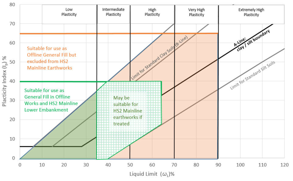
Lime stabilisation was identified as a key earthworks strategy to allow the reuse of site won soils to be maximised. Lime was chosen as a binder due to suitability to treat higher plasticity soils while avoiding potential trafficking issues of layers associated with faster curing mixtures. Long standing UK practice and specifications had set the minimum lime content for stabilisation with lime only at 2.5% addition by dry weight. Initial estimates, based on this figure, approximated that 400,000 tonnes of quicklime would be required for the earthworks in N1 & N2, a number that the UK lime market could not meet and therefore overseas import would be required.
Approach
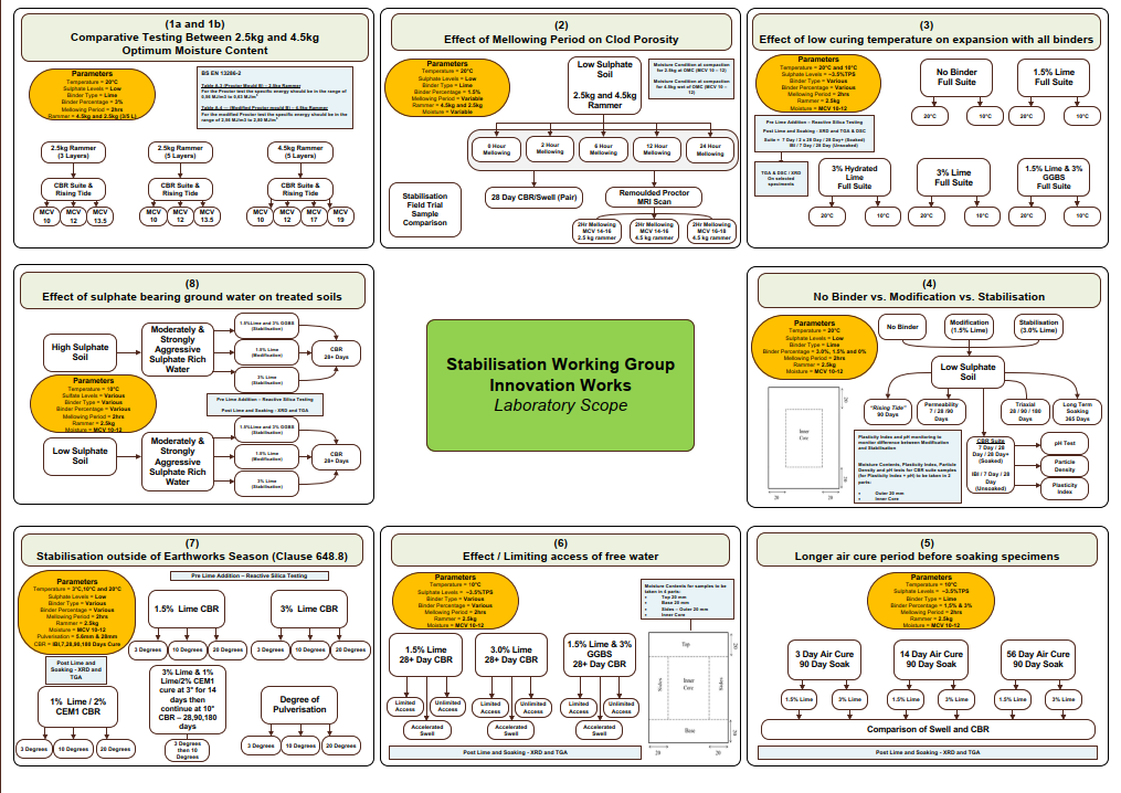
The project specification requirements for stabilisation were based on UK common practice, namely the specification used for stabilisation for road foundation layers. However, it was agreed at an early stage with HS2 Ltd that a programme of field and laboratory trials would be beneficial to the programme in developing this specification for bulk earthworks, to establish the optimal methodology to short term performance and long-term durability. The work set out to address the following objectives:
- Reduce quicklime content to achieve required performance and demonstrate durability.
- Reduce mellowing period to optimise earthworks efficiency assessing impact on clod porosity and swell.
- Determine optimal moisture condition and compaction approach to achieve short term in situ performance and mitigate the risk of potential future water ingress.
This work was part of a larger package of innovative stabilisation trials funded by and carried out in collaboration with HS2 (Figure 2). The scope of this work package was agreed with collaboration from main works contractor earthworks technical working groups, coordinated by the HS2 geotechnical lead. The total value of the HS2 innovation investment was £270,000.
Laboratory trials
The lab trial scope comprised three key stages:
- Characterisation of host material
- Baseline lab preparation methods
- Strength and durability verification for lower lime content
Characterisation of the host material
The material used in these trials was a Grade III/IV (MMG) from a quarry close to the trace of the mainline. At commencement of the trial there wasn’t access to site to carry out bulk sampling from trial pits, so this source was used as it was representative due to its proximity. Material from this source was subsequently imported to address earthworks shortfall further justifying its use. Results of the characterisation testing are shown in Table 1 Typical of intermediate plasticity soil encountered on the project suitable for lime treatment, with very low sulfate content indicating low risk of swell when treated.
|
Particle Size Distribution (PSD) |
Atterberg Limits |
ICL |
Chemical Analysis |
Optimum Moisture Content (OMC) | |||||||||||
|
Passing |
Passing |
Passing |
Passing |
Passing |
Passing |
Passing |
Liquid |
Plastic |
Plasticity Index |
Initial Consumption of Lime (%) |
pH |
TPS |
MDD 2.5kg rammer (Mg/m3) |
OMC |
Particle Density |
|
100 |
95 |
84 |
76 |
55 |
44 |
25 |
43 |
21 |
22 |
1.6 |
8.8 |
0.06 |
1.83 |
17.5 |
2.67 |
Baseline lab preparation methods
Before assessing the effects of a reduction in lime content a baseline lab preparation method was established. This involved determining the following:
- Compaction methodology
- Moisture condition
- Mellowing period
Compaction methodology and moisture condition
A key output of this work was to determine the compaction methodology to be used to provide sufficient short-term stiffness and satisfy long term durability requirements. An important specification requirement was to achieve low air voids (<5%) for stabilised cohesive fills. A further consideration was the potential benefit of targeting a higher compacted Maximum Dry Density (MDD) determined by the modified proctor (4.5kg rammer). However, to achieve the low air voids a moisture condition at or wet of Optimum Moisture Content (OMC) compared to OMC 2.5kg rammer is required correlating to maximum Moisture Condition Value (MCV) 12 as adopted in most UK specifications. Conversely complying with a high relative compaction for 4.5kg rammer would require a drier mixture contradictory to UK best practice and resulting in the low air voids not being achievable.
A range of moisture conditions and compaction regimes were trialled in the laboratory comparing the effect on compaction, air voids, swell and resultant soil strength over time. Using the 2.5kg rammer, samples were prepared at MCV 10 (OMC+2-3%), MCV 12 (OMC+1%), MCV 13 (OMC).
For comparison, using the 4.5kg rammer samples were prepared at MCV 10 (OMC+7-8%) and MCV 12 (OMC+5-6%). The results showed comparable densities of remoulded specimens from both rammer sizes and hence no significant difference in performance in respect of California Bearing Ratio (CBR) and swell over time.
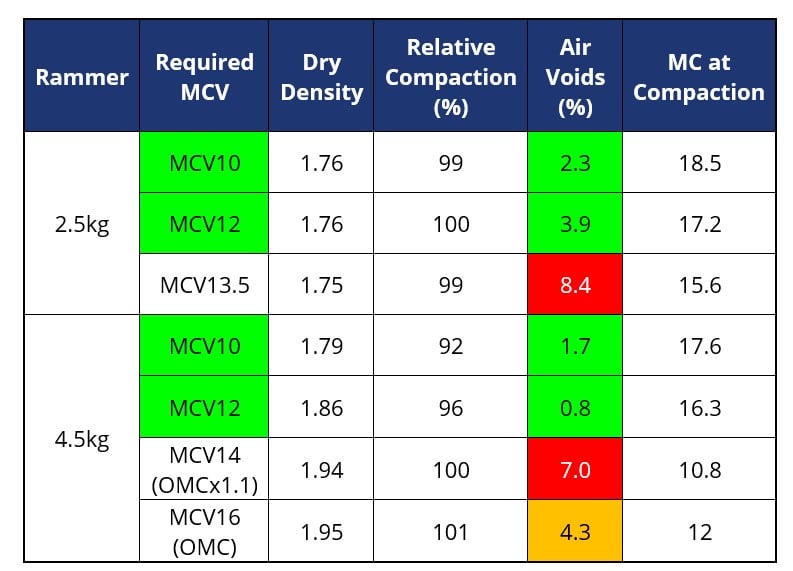
Comparisons of OMC/MDD relationships using 2.5kg and 4.5kg rammers on the same material typically show a lower OMC and higher MDD for the 4.5kg test compared to a higher OMC and lower MDD for the 2.5kg test (Table 2 above). It was important therefore to determine whether targeting high density with the need for corresponding drier mixtures leading to high air voids would be preferable compared to targeting wetter moisture condition and lower density but with lower air voids. The host weathered Mercia Mudstone (MMG) material chosen showed a difference of 5% in OMC between the two rammer methods and a difference in MDD of just less than 0.2Mg/m3.
Mellowing period
The specification required pulverisation via at least two passes of the stabilising machine and a period of between 24 and 72 hours for the lime to react with the soil. The mellowing requirement is specified to ensure sufficient clod breakdown for the lime to sufficiently coat the particles and mitigate the risk of untreated clods. As highlighted in Lime stabilisation for earthworks: a UK perspective (P. Beetham 2015) [2] there is a risk that too long a mellowing period may be counterproductive and introduce a higher clod porosity and corresponding durability risk due to water ingress. It is acknowledged that this minimum mellowing requirement has been in place for a significant number of years informed by early stabilisation plant efficiency and lime reactivity at the time. Long mellowing periods would impact the sequencing of earthworks activities when placing multiple layers for embankment fills. A shorter mellowing period would allow completion of layers within the same shift and avoid potentially sterilising areas while mellowing was being undertaken. With the need for multi-layer treatment to allow bulk earthworks filling, it was important to find a solution to improve productivity to meet the programme requirements.
With current lime production being highly reactive and modern stabilisation plant being highly efficient, shortening of the mellowing time was targeted.
Laboratory trials comprised of adding lime to material in the lab then leaving to mellow for 0, 2, 6, 12 and 24 hours before compacting then soaking in water for 28 days. The Pulverisation, remoulded density, air voids at the time of compaction with CBR and linear swell after each mellowing period was tested. It was more difficult to remould the sample to achieve low air voids for those samples subjected to longer mellowing periods. The results showed that a 2-hour mellowing period provided the lowest linear swell but still achieved suitable strength and still achieved the required pulverisation. A shortest practical mellowing time was adopted consistently across the site trial areas. Following spreading of lime, mixing and compaction this typically resulted in 1-2 hours. Pulverisation tests immediately prior to compaction confirmed compliance with the pulverisation requirements including for the lowest lime content trialled.
Strength and durability verification for lower lime content
To reduce the demand and therefore eliminate the consequential cost and carbon of import from overseas, laboratory stabilisation trials were to be carried out with the aim of demonstrating the suitable performance of a stabilised fill with reduced lime content. Efficiencies from European high speed rail solutions were identified indicating that a lower lime content of 1.5% may be considered to provide the required performance. The trials would have to prove the long-term durability of the material and therefore a year was selected as a suitable period of time to validate performance against stabilised mixtures containing high binder content. Assessment following full immersion in water for one year should be conservative and more onerous than field conditions however this gave a method of assessing durability and performance. Mitigating loss of strength when measured using California Bearing Ratio (CBR) test over time was considered a suitable means of assessing the risk of localised softening should water enter the earthworks during service.
The specification required stabilisation rather than short term improvement with a minimum of 2.5% quicklime or the Initial Consumption of lime (ICL) value. The ICL is determined when the pH rises above 12.4 and the material is then considered to be stabilised. In order to reduce lime content, an alternative method for demonstrating long term stabilisation performance was required. BS EN 16907-4:2018 3.20 provides the following definition of stabilisation:
“Soil stabilisation – operation consisting in obtaining a homogeneous mixture with binder(s), and optionally with water, which properly compacted significantly changes (generally in the medium or long term) the characteristics of the soil in a way that renders it stable, particularly with respect to the action of water and frost.”
To demonstrate compliance with the standard definition of stabilisation, long term durability as well as successful pulverisation needed to be demonstrated. Trials were carried to compare performance at 1.5% and 3% quicklime addition. 1.5% lime addition is common French high speed rail practice and was considered the practical minimum spread rate achievable.
.
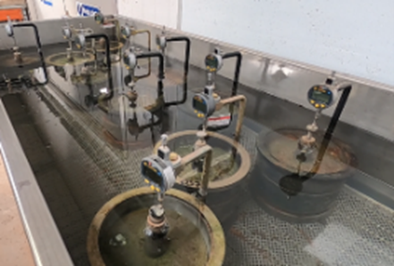
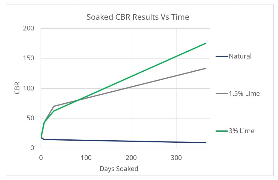
The testing involved comparing unsoaked specimens against soaked CBR specimens for up to 365 days (Figure 3). Samples were also removed from soaking and tested for CBR at a range of ages. Figure 4 shows the development of strength over time, the 0% samples showed a slight decrease over the year of soaking but 1.5% and 3% showed an 8- and 10-fold increase respectively, the linear swell was negligible in all specimens.
The pH of the mixtures at various lime contents was also measured. The pH of the lower lime content (1.5%) averaged 11.5 compared to greater than 12.4 at the higher lime content (3%). The trials proved that despite the lower pH and lower addition being below ICL, stabilisation was still achieved.
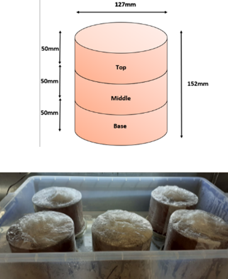
To determine the impact of moisture condition on swell risk and corresponding durability, a bespoke test was adopted from previous papers, references 3-5. This test is referred to as ‘The Rising Tide’. Specimens were partially submerged in water and the moisture content was taken before and after testing to assess whether moisture was drawn into the specimens – the specimens were sectioned into top, middle and base (Figure 5) to show how the moisture had risen up the specimen.
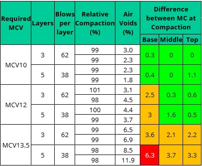
Green – <2% change from pre soaking
Amber – 2 to 4% change
Red – >4% change
The results (Table 3 above) showed that where a wetter moisture condition was adopted on mixing and compaction, a negligible change to moisture content was observed despite immersion in water. Conversely drier specimens exhibited a higher change in moisture content demonstrating the risk of suction should the material be subjected to water ingress.
This is an essential finding as if minimal moisture is drawn into the material, then there shouldn’t be a strength reduction. As a result, wet of optimum moisture contents prior to compaction were targeted.
Having determined the optimal moisture condition to achieve the low air voids requirement, further validation of mixture durability was considered via assessing the permeability of the treated material. samples were prepared at natural (without lime) and at 1.5% and 3% lime addition. The results for the 1.5% and 3% tests were comparable with both showing and reduction in permeability by two orders of magnitude compared to the natural/untreated material. This moved it from 10-8m/s to 10-10m/s (Table 4 below). This further evidenced the long-term durability for compliance with the stabilisation requirement, demonstrating 1.5% addition of lime provides a durable solution.
|
Lime content |
Coefficient of Permeability (k) | ||
|
7 Days |
28 Days |
90 Days | |
|
0% untreated |
5.50E-8 |
1.60E-8 |
6.00E-11 |
|
1.5% |
4.00E-10 |
3.00E-10 |
2.40E-11 |
|
3% |
4.20E-9 |
4.30E-11 |
9.70E-10 |
Four consolidated Undrained (CU) triaxial tests were carried out on natural and stabilised specimens (1.5% and 3%) which were left to cure for 28, 90 and 180 days. The results shown below in Figure 6 demonstrate the increase in effective cohesion (c’) for the stabilised specimens with increased cure period however effective angle of friction (Φ’) remained largely the same. The natural specimens showed no improvement in strength as expected.
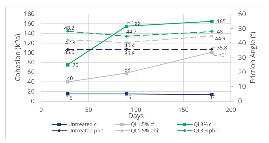
While the values of Φ’ reported do not increase over time, the results all exceed those expected and used to inform earthworks slope stability design. Optimisation of earthworks design has been possible for some assets based on the increased performance realised.
Field trial
A full scale 10-layer trial embankment was built with Mercia Mudstone comprising untreated, 1.5% and 3% lime addition sections. The lime stabilised sections were further divided into wet of and optimum moisture content (OMC) areas. The MCV of these were as follows:
OMC – MCV14-16 – moisture condition to target high density (compared to 4.5kg rammer) OMCx1.1 – MCV10-12 – compaction against 2.5kg rammer target with low air voids (normal industry practice)
The specification limits compacted layer thickness to 250mm unless otherwise proven by trials. Each compacted layer thickness was targeted at 300mm to improve outputs. 300mm layers also allows testing by direct measurement using a nuclear density gauge to align with compliance control for the main works.
The layout of the trial areas is shown in Figure 7 below.
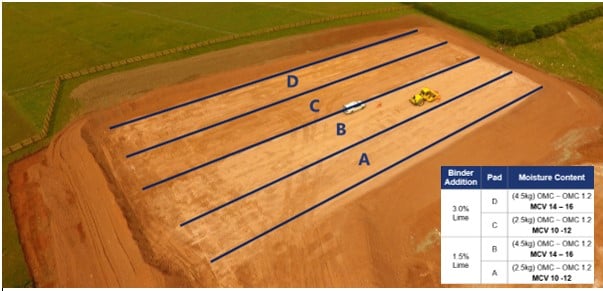
The wetter material moisture content was targeted at MCV10-12 which equated to OMC-OMC+3% versus 2.5kg rammer. The drier material moisture content was targeted at MCV14-16 equating to OMC-OMC+3% versus 4.5kg rammer. The compliance of in-situ testing results is summarised as follows (Table 5):
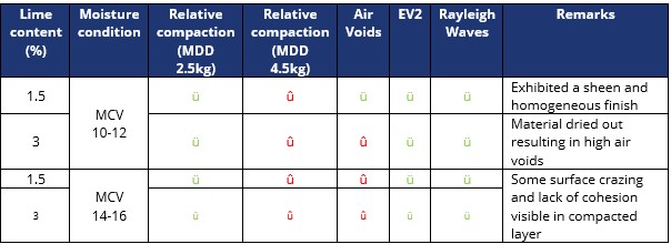
At the drier moisture content, the relative density increases but the air voids also increase. With wetter material the relative compaction is lower, but the air voids are also reduced. The field trial demonstrated that when using drier mixes to target higher relative compaction, the air voids were consistently too high and therefore the specification limit of 5% was unachievable. With wetter material the air voids were much lower and within the specification limit of 5%, however the relative compaction was lower but repeatedly achieving greater than 98% (vs. 2.5kg rammer) and therefore suitable for use in high-speed rail upper embankment fill.
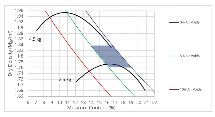
Shaded box in Figure 8 shows typical range of in situ density and air voids achieved in the field based on the target MCV10-12 moisture condition.
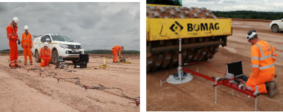
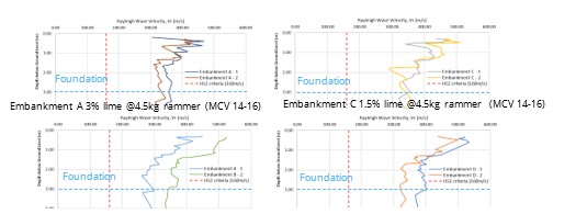
Although some results were higher for the 3% lime addition section compared to 1.5% lime, the EV2 results and Rayleigh wave testing showed that all the stabilised sections complied with the >60MPa limit for EV2 and the 120 m/s shear wave limit (Figure 9 & 10 and Table 6).

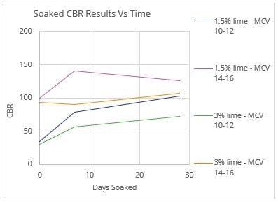
A range of samples from each trial section were taken for laboratory testing and moulded up on site immediately prior to compaction. The results for Immediate Bearing Index (IBI) longer term unsoaked and soaked CBRs and swell over time were similar for the two lime contents at the same moisture condition and compaction. The drier mixtures exhibited higher IBI but exhibited a reduction of CBR on soaking (figure 11). The drier mixtures also exhibited higher swell over time albeit within the technical standard limits. All the samples taken in the field correlated well with the laboratory trial scope.
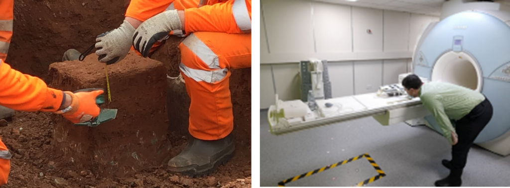
Due to the difficulties of measuring in situ air voids on stabilised materials, further assessment was undertaken. Following the field trial, an MRI scan of a large block of undisturbed ground was carried out to validate the calculated air voids, although this was unsuccessful (Figure 12).
Outcomes
The key outcomes from this work are summarised as follows:
- Laboratory trials highlighted satisfactory performance at lower lime content (1.5%) with durability demonstrated to satisfy the definition of stabilisation give in BS EN 16907-4:2018.
- Field trial validated lab trial results demonstrating satisfactory field performance achieved using reduced lime content (1.5%) providing similar results to that of material containing 3% lime.
- Mellowing period reduction from 24-72 hours to 0-2 hours improving site output.
- Compacted layer thickness increased from 250mm to 300mm with density and air voids satisfactory. In situ testing with nuclear gauge validated and aligned to compliance testing regime
- Achieving low air voids (<5%) was not possible if high relative compaction versus 4.5kg rammer was to be targeted. minimum relative compaction of 98% of 2.5kg rammer MDD adopted.
- Satisfactory in situ performance achieved in respect of stiffness and dynamic resilience for reduced lime content and revised compaction target.
- Within HS2 Phase One N1 & N2 slope gradient designs have also been optimised based on the use of stabilised materials
Table 7 below shows the changes to the specification that were agreed as a result of this work:
| Ref | Property | Specified Requirements | Agreed Solution |
|---|---|---|---|
|
1 |
Moisture Condition |
Maximum MCV 12 / Minimum moisture content of OMC vs. 2.5kg rammer |
Unchanged |
|
2 |
Relative Compaction |
>98% of MDD (4.5kg rammer) UEF >95% of MDD (4.5kg rammer) LEF |
>98% of MDD (2.5kg rammer) UEF >95% of MDD (2.5kg rammer) LEF |
|
3 |
Air Voids |
<5% (Cohesive) |
Unchanged |
|
4 |
Durability (Swell) |
<3% Linear Swell |
Unchanged |
|
5 |
Ev2 |
>60Mpa UEF >45Mpa When within 1m of LEF |
Unchanged |
|
6 |
Mellowing Period |
24 to 72 hours |
0 Hours (No mellowing) |
|
7 |
Minimum lime content |
Minimum 2.5% or ICL |
Minimum 1.5% Lime for cohesive soils |
|
8 |
Layer Thickness |
Maximum 250mm unless otherwise proven through trials |
300mm as proven through trials |
This work was part of a larger package of innovative stabilisation trials funded by and carried out in collaboration with HS2. By working with HS2, the specification was changed to set the minimum lime content to 1.5% subject to individual trials on asset specific materials.
This work has directly led to the reduction in lime content required and ultimately reduced the quantity of lime to be supplied to the project. At the time of writing a saving of 1% lime equates to circa 140,000 tonnes reduction in lime required to be purchased. However, to ensure sufficient capacity is available and mitigate any unforeseen requirements, a reduction of circa 70,000 tonnes of lime is forecast. This reduction has led to a saving of at least £12.5 million and more than 55,000 tonnes of carbon. In addition, the total quantity of lime now required can now be met via UK production. This mitigates the risk of needing imported lime at higher cost.
Learnings and recommendations
This work has conclusively shown that lime stabilisation can be carried out and achieve similar durability and performance with a 1.5% lime addition, a 40% reduction on the UK normal practice minimum of 2.5%. Learning points were as follows:
- A long-term stabilisation reaction is achievable at lower than previously specified lime contents. While lower lime contents may promote an increase in pH to around 11.5 compared to 12.4 to achieve ICL, alternative methods have demonstrated long term durability to meet the standard.
- The moisture content of the mix is key for attaining a durable fill material, too dry and there will be a tendency to draw up water should it be available. This would lead to a drop in strength. The target moisture should be just wet of optimum prior to compaction which equated to roughly MCV 10-12 for the MMG used in these trials.
- Increased lime content resulted in significantly increased water demand which was counterproductive. Higher lime content also resulted in the material drying out more rapidly resulting in higher air voids than the specification requirement.
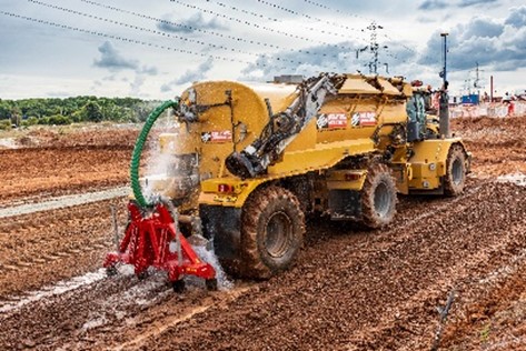
- Dedicated bowser and ripper plant for pre-conditioning to achieve greater productivity (Figure 13)
- A shorter mellowing period of less than 2 hours is appropriate for modern mixing plant and lime sources used. This also mitigates potential risk of increased porosity within the clods of treated material when longer mellowing periods are adopted.
- The pulverisation of the material prior to mixing lime and compaction is important to ensure thorough mixing of the lime into the material.
- It is preferable to focus on achieving lower air voids at the correct moisture condition (MCV10-12 as referenced above for lime stabilised soils) rather than chasing higher relative compaction in isolation.
- Understanding the changes to MC, MDD and particle density over time after lime addition informed site control and testing and changes to procedures to ensure accurate monitoring:
- Sample immediately after mixing with samples for IBI and soaked CBR moulded up immediately on site to ensure moisture condition is representative of in-situ material.
- Additionally, initial (wet) weights for disturbed samples for moisture content tests were recorded on site using a portable balance to avoid moisture loss in transit to the laboratory.
- Correlated Nuclear Density Gauges specifically for moisture content readings as well as density to eliminate moisture reading problems.
- Samples for determining reference OMC/MDD in the lab are taken from the mixed material to the laboratory and tested immediately on receipt to avoid changes to MDD/PD over time.
- Separate material by weathering grade – GRIII/IV needs less water for stabilisation and GRI/II more suited to landscape/highway fills.
- GRII MMG required twice the quantity of water addition compared to GRIII/IV MMG.
- Each material should be trialled separately to establish this range as every material is different.
Conclusion
Although the trial results reported above were based on MMG, over 40 individual laboratory trials and 13 field trials have been carried out, to validate the use of lower lime content across all N1 & N2 geology types including solid geology and superficial deposits.
Careful material selection and good pulverisation enabled shorter mellowing periods. The demonstration of moisture condition to achieve low air voids with corresponding durability after long age testing, validated the adoption of lower lime content which is expected to change industry approach for stabilised mixtures. The findings have been shared across HS2 Phase One main works contractors and designers. A detailed technical report has been produced which will inform future knowledge share and articles.
A summary of the outcomes has also been published by Britpave in a best practice publication: BP 75 “Forwarding soil stabilisation” (2023) [6].
This learning legacy specifically highlights a significant change to lime stabilisation standard practice with opportunities to adopt this on future projects. This work is expected to change industry approach and inform future specifications.
Acknowledgements
Nick Sartain – HS2 Geotechnical Lead
Paul Beetham – HS2 Lime Stabilisation Technical Specialist
Richard Harris – BBV Materials Engineer
Sam Boden – BBV Materials Engineer
BBV Lab team
References
[1] C F Notman (2011) Durability testing of fine grained stabilised soils, MPhil thesis, University of Nottingham, UK
[2] Beetham, Paul; Dijkstra, Tom; Dixon, Neil; Fleming, Paul; Hutchison, Robert; Bateman, John (2015). Lime stabilisation for earthworks: a UK perspective. Loughborough University. Journal contribution. https://hdl.handle.net/2134/21150
[3] Effects of soaking on a lime stabilized clay and implications for pavement design, BOZBEY et Al. Geomechanics and Engineering, Vol. 24, No. 2 (2021) 115-127
[4] The effect of pulverisation quality on the durability of stabilised clay soils against water ingress, J. PEARS BEng Dissertation, 2016
[5] Evaluation of structural properties of lime stabilized soils and aggregates, D. N. Little, Volume 3: mixture design and testing procedure for lime stabilized soils, Prepared for the national lime association (2000)
[6] Britpave (2023) BP75 – Forwarding soil stabilisation
Supporting materials
HS2 Earthworks Technical standard – Extract provided in Figure 1
SCEW 600 series – referred to as the “specification”
BS EN 16907-4-2018-Earthworks soil treatment with lime
Peer review
- Victor GomezHS2 Ltd


