Shallow TBM launch of the Northolt Tunnel West TBMs at West Ruislip
Launching tunnel boring machines (TBMs) from a station box or launch shaft is a delicate operation that requires careful planning to maintain safety. Seven TBMs excavate the tunnels on HS2 Phase Onethe southern section of the High Speed Two (HS2) Phase One route Lots S1 and S2 tunnels and will bore an approximately 23km twin tunnel connecting Euston Station in London, Old Oak Common in North Acton and West Ruislip. Three out of seven TBMs are set to be launched in very special conditions due to shallow alignment constraints.
This paper describes the structural and geotechnical works designed for the West Ruislip area, where two TBMs will start the bore of the HS2 Northolt Tunnel West (NTW). These works include extensive piling, civils, ground treatment and soil works. The innovative method described in this paper and its implementation in the HS2 Project promote confidence in economic and environmentally sustainable technical solutions with a minimum carbon footprint.
- Written by
-
Helena Castellvi (SCS/TYPSA Ltd)

-
Xavier Torelló (SCS/TYPSA Ltd)
-
George Doulkas (SCS/STRABAG UK)

- Resource type
- Resource type: Technical Paper
- Intended audience
- Contractors
- Tags
- Ground Improvement posts
- Launch Box posts
- Portal posts
- Shaft posts
- TBM posts
- TBM Launch posts
- TBM Logistics posts
- tunnel posts
Introduction
The Northolt Tunnel is part of the southern section of High Speed Two (HS2) Phase One between Euston Station and West Ruislip – Lots S1 and S2 (Area South), being delivered by the SCS Integrated Project Team.
Northolt Tunnel West (NTW) are the western 8km tunnels of the HS2 Lot S2. The NTW consists of twin Tunnel Boring Machine (TBM) tunnels with an internal diameter of 8.80m and a ring thickness of 350mm. The launch of the TBMs is from West Ruislip Portal and they excavate through Greenpark Way ventilation shaft in the east.
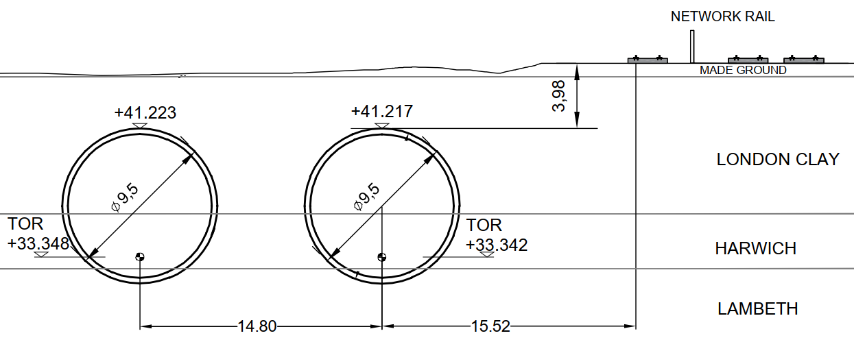
The NTW TBMs break-in will be done from West Ruislip Portal (WRP) headwall in shallow open-air conditions just a few meters below the ground surface. Relevant constraints in this area include the Network Rail tracks located 20 metres south from the centre of one of the tunnels.
The soil above the tunnel crown consists mostly of man-made ground and weathered clay. Groundwater level of the weathered clay unit is located almost at ground level.
To mitigate the risk of excessive settlements or ground surface collapse due to over excavation, a range of structural and geotechnical works are proposed, consisting of:
- Launch sealing installation around the tunnel eye at the portal headwall to limit the inflow of water and annulus grout through the annular void.
- Starting box – erection of reinforced concrete pile walls on both sides of the running tunnels covered by a reinforced concrete slab creating a protective box around the initial tunnel drive. This provides confinement pressure and is intended to minimise volume loss in case TBM or ground problems are encountered.
- Ground improvement methods to increase the strength of the soil above the tunnel crown, to stabilise ground and smooth the launch.
- Ballasting at ground surface level to provide confinement of the TBM and prevent tunnel flotation.
In order to assess the effectiveness of these measures, a series of different scenarios and methodologies have been developed. The study was based on empirical Gaussian curve correlations and on Plaxis® 2D and 3D non-linear finite element models. In addition, a detailed review of TBM parameters was implemented to provide greater control over the excavation works. The measures were reviewed for constructability and also considered benchmark projects and the three academic studies[1], [2], [3] outlined in the reference section of this paper.
Shallow launching solution
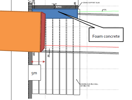
Figure 1 shows the 3D sketch form of the tunnels, the headwall (front piles), the starting box (lateral piles and slab), the treated ground and the fill on top of both the latter and the slab.
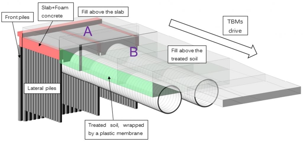
The TBM launch starts at the West Ruislip Portal through a temporary sealing installed around the tunnel soft eye in the portal headwall to mitigate the risk of water inflow and ground drag inside the launching structure.
After the break-through of the headwall, the TBM bore continues in the starting box – section A in Figure 1 above. It consists of frontal and lateral piles (around 25m length in depth) and a top slab loaded with landfill. There are three meters of foam concrete below the slab, which provides stability of the excavating crown. The length of the launching box in the TBM drive direction extends up to 20 metres.
In front of the launching box in the direction of the drive, a further geotechnical solution has been implemented to mitigate tunnel small overburden – section B in Figure 1 above. The ground located at the crown of the tunnels is substituted by a treated soil. A plastic membrane wraps the treated soil and the required overburden is achieved with landfill on the top.
The distance between the twin tunnels axes at the break-in is less than 14 metres, which gives about 4.5m clearance between the tunnels. This distance gradually increases and slightly exceeds 15 metres between the axes, at the point where the TBMs leave the shallow launching area.
Similar shallow launching of TBM drives have been reported on projects such as Line 9 Metro Barcelona, on section 2 between Parc Logístic – Zona Universitari [3].
Starting box design
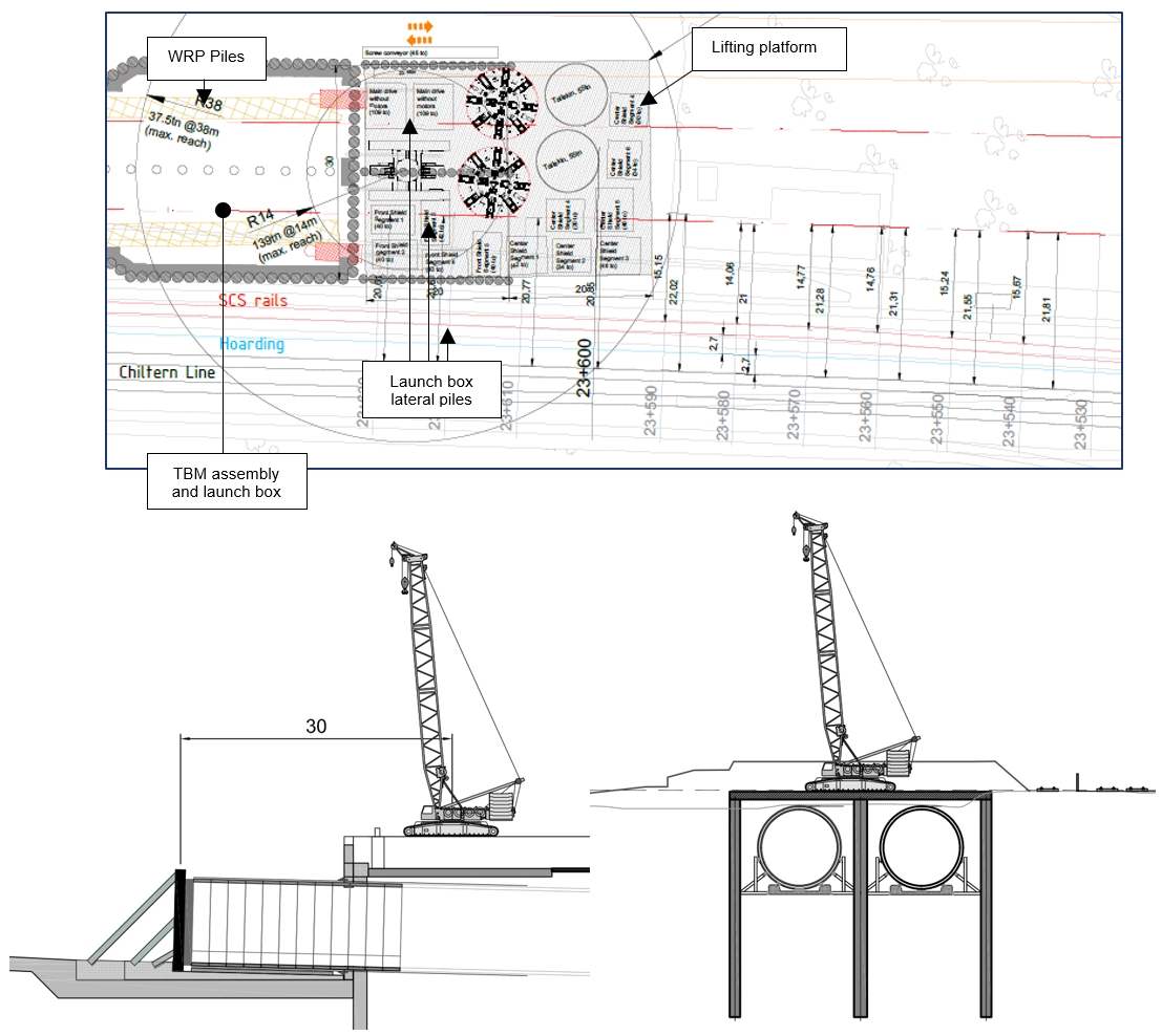
The starting box is designed to be able to cope with a TBM assembly crane load and to minimise volume loss during the launch.
Two TBMs are going to be assembled inside the launch boxes of the WRP. A heavy crane is required to lift down all the TBM parts. A lifting platform requires a hardstanding capable of bearing the expected loads and should not produce additional settlement that may impact the safe operation of the ancillary equipment. To satisfy this constraint, a slab founded on piles is introduced outside the WRP headwall, that will act as a temporary footing for the crane. In addition, this element will provide a protected area where the TBM crosses between the deep piles supporting the slab. The following figures depict the crane operation over the starting box at the West Ruislip shaft, where two TBMs for Northolt Tunnel West (NTW) bores are going to be launched.
The slab-piles system has a complex structural function which must successfully deal with the following main load stages:
- Temporary loads of crane operation.
- The temporary stage while the TBM is driven below the slab.
- Long term stability.
The design approach for these structures is described below.
For the first stage, the slab was conventionally designed as a load bearing slab founded on piles, taking into primary consideration the cranes operating on top of it.
For the second stage, the critical loads were associated with the TBM driving below. The cranes on top were considered as not operating and a distributed minimum load acting as soil infill was introduced onto the slab to ensure short term stability. This second stage can also be divided in two discrete sub-stages:
a. The first sub-stage is completed just after the TBM drills through the front wall soft eye of the portal and approximately after 5 metres. Then, as it is recommended for good practice, an inspection of the TBM cutterhead will be carried out to check the cutting tools. Conditions for this front intervention will be improved by using foam concrete underneath the slab as a partial ground substitution to create a “stable crown” (Figure 3).
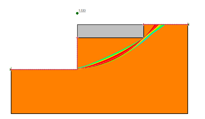
To ensure geotechnical stability with no face pressure a model was created with a simplistic 2D longitudinal analysis using Slope®. Figure 4 illustrates the failure surfaces that exceed the starting box limits (slab-foam concrete length). This software that considers limit equilibrium methods, gives a safety factor of 1.53, which is higher than 1.
b. The second sub-stage begins just after the completion of the atmospheric intervention and is completed after the TBM shield runs through the entire length of the starting box. Given the special conditions of extremely shallow overburden between the tunnels and the slab; and considering the challenges of preventing over excavation while tunnelling, the piles on either side were calculated considering that the inner ground is fully excavated.
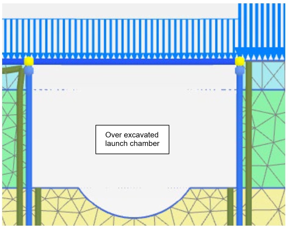
This hypothesis gives a good level of design robustness to the piles design and ensures that sensitive, close proximity elements as the Network Rail tracks are not damaged, even in the worst-case scenario, from any tunnelling induced deformations.
c. The third stage, with regards to the long-term stability of the starting box, is achieved by considering sufficient infill above the slab to counteract tunnel flotation.
Ground improvement design
An extended series of brainstorming sessions were carried out by the tunnelling team, with the goal to produce several different solutions to the issues that are expected to occur once the TBM has advanced outside the starting box. The objectives of these sessions are listed as follows:
- To ensure a minimum overburden along the alignment that is capable to counteract the TBM face pressure while boring in shallow areas;
- To limit the soil displacements, and effect on the segmental lining of the first tunnel while driving the second TBM tunnel in close proximity;
- To provide measures that ensure long term stability against tunnels buoyancy in shallow areas;
In order to balance the geotechnical conditions, the given geometrical constraints and the need for a cost-effective solution, the design shown below has been developed for the sections adjacent to the starting box.
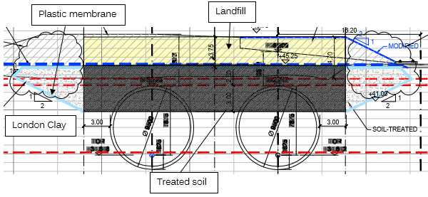
As shown in the upper cross-section the solution is composed of the following measures:
- Partial ground replacement by treated London Clay:
Soft Made Ground in the front and the crown of the tunnel drive will be substituted by a material with cohesive properties that not only provides for a better TBM performance but also helps reducing the risk of over-excavation. This will also improve the conditions needed to apply the designed TBM face pressure.
This ground replacement ensures that relatively stiffer materials will occupy the space between the tunnels (upper central pillar) which, combined with a better TBM driving performance, aids in the reduction of the imposed deformations on the first tunnel while boring the second one.
- A minimum amount of fill above the tunnel:
The upper surface landfill provides an equivalent vertical dead load to counteract the TBM pressure, thus providing short term stability while advancing the machine and ensuring the long-term stability against tunnel buoyancy.
- A plastic membrane enveloping laterally and topside the treated soil:
Using a watertight plastic membrane to wrap the treated soil, the risk of pressure release while driving the TBMs is reduced. Therefore, while the TBMs face pressure is counteracted with the upper landfill, the plastic membrane ensures no liquid pressure release occurs avoiding the risk of the total loss of the TBM face pressure.
The launch zone has been analysed with finite element software PLAXIS® 3D to correctly capture the face stability mechanisms described in the previous sections and to check the imposed effects in the first tunnel driven, as shown in Figure 8.
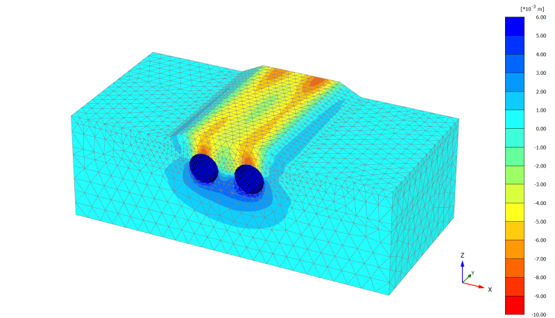
Current design displacements have been considered for the Ground Movement Assessment design. The most affected area by possible large displacements is just above the tunnel drive, Network Rail is relatively far compared to the extreme shallow condition of the tunnels.
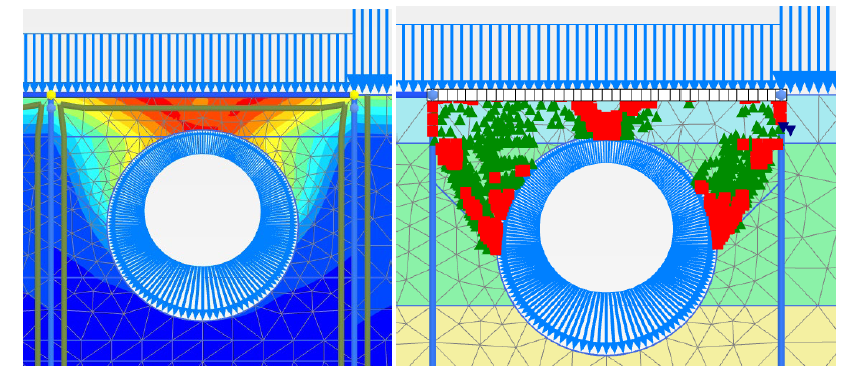
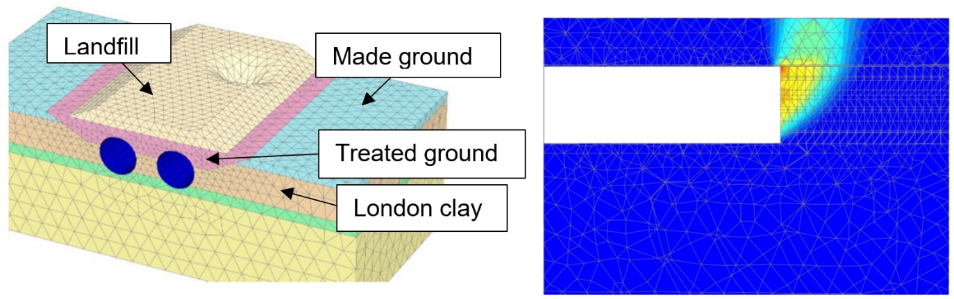
The safety factor against sink holes was checked by means of c-ⱷ(phi) reduction procedure in PLAXIS® 3D, as shown in the images below, which correspond to the hypothetical imposed situation of failure due to ground parameters reduction.
A surface blow out scenario due to excessive pressure compared to the dead load of the infill is directly controlled by the total vertical load of the ballasting at surface tunnel. The additional dead load above the small overburden ensures short term stability for the TBM drive and provides counterweight for buoyancy in the long term.
Additional measures for optimal TBM operation
Based on the challenging TBM launch drive conditions, additional measures for optimal TBM operation and segment construction were assessed as follows:
- Learning curve from the first TBM operation. As explained above, one of the more challenging tasks will be driving the second TBM next to the first tunnel. An optimised and intense analysis of the tunnelling parameters achieved while driving the first tunnel may then be employed. The more experienced TBM crew will be recommended to drive the second machine in this area.
- Face pressure while driving the starting box must be lower than 0.6bars, and while driving in the ground treated area must be higher than 0.3bars and lower than 0.6bars (measured at crown) with full chamber driving.
- Settlements just above the tunnels after driving will affect an area that is a safe distance from the nearest sensitive elements like Network Rail tracks. Based on the observed excavation experience from the first drive, additional measures could be considered prior to driving the second TBM.
- The tunnel lining incorporates additional provisions such as leaving the stainless steel bolts in the segments, to increase the stiffness of the lining design if displacements imposed by the second drive exceed certain thresholds.
- The area above the tunnels has a long-term limit of surcharge load up to 20kPa after the tunnels are constructed, as a result of the extremely reduced overburden.
- In this area the general instrumentation monitoring is going to be placed. In further stages of development of the solution additional levelling and instrumentation will be included.
Conclusion
This paper has summarised the design measures and construction procedures developed to permit the safe launch of TBMs with limited overburden.
The design measures adopted include:
- A headwall of piles to launch the TBMs, at the shallowest location.
- A starting box with piles at the sides and between the tunnels, covered by a slab with fill on top.
- After the starting box, while the tunnels go deeper, treated ground on the upper half of the TBM tunnels and fill on top. A plastic membrane has been included to reduce the risk of pressure release while driving the TBMs.
This procedure has been designed in coordination with the TBM construction team. The procedure described in this paper is innovative, however some experience already exists in similar solutions that have been accomplished in extreme shallow tunnelling in other projects where authors have been involved. Its use in the HS2 Project makes an innovative impact; improves constructability, eases complexity, benefits in economic and environmentally sustainable solutions where face TBM pressure and tunnel buoyancy counteract with landfill instead of a massive concrete structure.
Acknowledgements
Special thanks to Skanska, Constrain and Strabag (SCS JV) UK for their kind permission to reproduce results from studies that led to the detailed design solution for the West Ruislip shallow launching of TBM’s.
References
[1] Oldenhave, A. H. (2014). Starting a large diameter TBM from surface. Feasibility study for the Netherlands. Master of Science Thesis. TU Delft.
[2] Torelló Ciriano, X.; Gost Mayans, X.; Castellvi, H. (2019). Control de presión del frente en un túnel EPB para la reducción de asientos a su paso bajo el aeropuerto de Barcelona. AETOS – Tunnelling below Barcelona Airport: Lessons Learned in the control of EPB TBM Face Support Pressure for Settlement Risk Management, WTC2020.
[3] TM-00509.5G-M2 Project, TYPSA author, Line 9 Metro Barcelona, section 2 between Parc Logístic – Zona Universitaria
Peer review
- Colin Rawlings, Lead Tunnel EngineerHS2 Ltd