Special segment design for cross passages and shaft passages
Operational considerations for the High Speed Two (HS2) TBM twin tunnels require cross passage connections and ventilation openings that are critical for not only the safe operation but also for the construction process. Conventionally, temporary support is used to ensure the stability of these openings in the tunnel lining. The use of special segments reduces the negative impact on the construction programme and TBM logistics.
This paper focuses on the design of Northolt Tunnel West (NTW) which is the 8.8m internal diameter twin bore tunnel located between the 15,600 and 23,400 kilometre section of HS2 Phase One.
The special segments are geometrically equal to the standard segments but are more heavily reinforced and contain embedded structural frames and tension rods to transfer the load to the adjacent rings and to avoid stepping between segments.
In the NTW, the design of the special segments has been achieved with the following procedure:
• Ground load derivation: Accurate estimation of the loads acting on the segments around the opening using Plaxis® 3D, considering the ground properties, the construction stages and the most unfavourable dewatering hypothesis.
• Member forces and stepping between segments calculation: Accurate structural analysis carried out using SAP2000® considering the derived ground loads, non-linear links between rings acting under compression only and a remaining residual propulsion force.
• Study of the construction compatibility with TBM advance, with low interference in the TBM advance ratio and feasibility to be executed from the TBM.
• Design based on accurate tolerances of the embedded steel frames inside the special segments compatible with the construction sequence.
This design procedure allows, although with a higher design effort, a more effective construction process with no additional temporary structures required around the openings to prop the tunnel lining and little interference in the TBM advancement ratio.
- Written by
-
Helena Castellvi (SCS/TYPSA Ltd)

-
Xavier Torelló (SCS/TYPSA Ltd)
-
George Doulkas (SCS/STRABAG UK)

- Resource type
- Resource type: Technical Paper
- Intended audience
- Contractors
- Tags
- dowels posts
- opening frame posts
- segmental lining posts
- special segments posts
- TBM tunnels posts
INTRODUCTION
This paper focuses on Northolt Tunnel West which is part of the southern section of High Speed Two (HS2) Phase One – Lots S1 and S2 (Area South) – which includes the Northolt Tunnels and the Euston Tunnel and Approaches, being delivered by the SCS Integrated Project Team.
In order to maintain structural integrity while implementing openings and “break-outs” in the tunnel lining, temporary propping structures are often required. The construction process and the volume of these temporary works is unavoidably linked with impacts on site logistics, construction programme and Tunnel Boring Machine (TBM) advance delays. The proposed technical solution considers these construction constraints and provides a way of mitigation by specially designed segments.
These special segments are geometrically equal to the standard segments, albeit heavier due to a higher reinforcement content. Furthermore, they contain embedded structural steel frames and tension rods to transfer the load to the adjacent rings and increase the stiffness around the opening.
Special segment design for ease of constructing openings in the TBM tunnel lining is based on the following objectives:
- Constructability compatible with TBM advance with reduced interference in the TBM advance ratio and feasible to be executed from the TBM.
- Design of accurate tolerance of the embedded steel frames inside the special segments compatible with the construction sequence.
- Provide the capability of epoxy grouting for improved durability.
- Design of a staged construction sequence for the adjacent cross passage and/or tunnel ventilation openings, compatible with the structural capacity of the special segments, and with a controlled stepping between segments to avoid poor operation of tunnel segmental gaskets.
CHARACTERISTICS OF THE SPECIAL SEGMENTS
The special segments are required to withstand more adverse loads structurally than typical segments, and therefore, heavier reinforcement is required:
- Special segments with reinforcement (17Φ25 per side)
- Steel profiles embedded in the concrete to transfer and distribute the loads
The special segments are also designed to create a structural system between adjacent rings for load transfer. This is achieved by a combination of:
- Dowels between rings fixed into pipe sleeves in the special rings.
- Tension rods between special segments fixed using pipe sleeves and tensioned with a torque tool.
- Piping for an epoxy grout to fill above sleeves.
These connection elements are assembled in their sleeves once the ring is completed in the TBM, utilising reduced machinery and limited impact in the TBM advance ratio. See figure 1
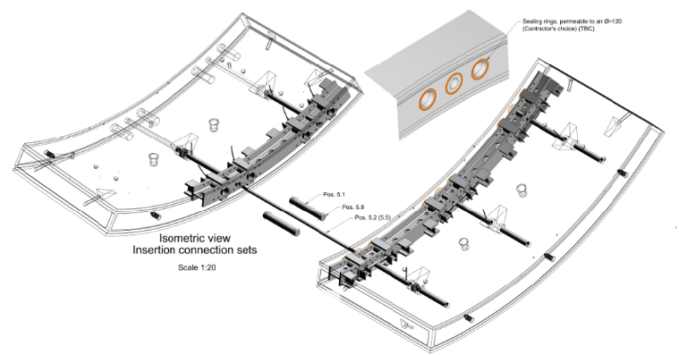
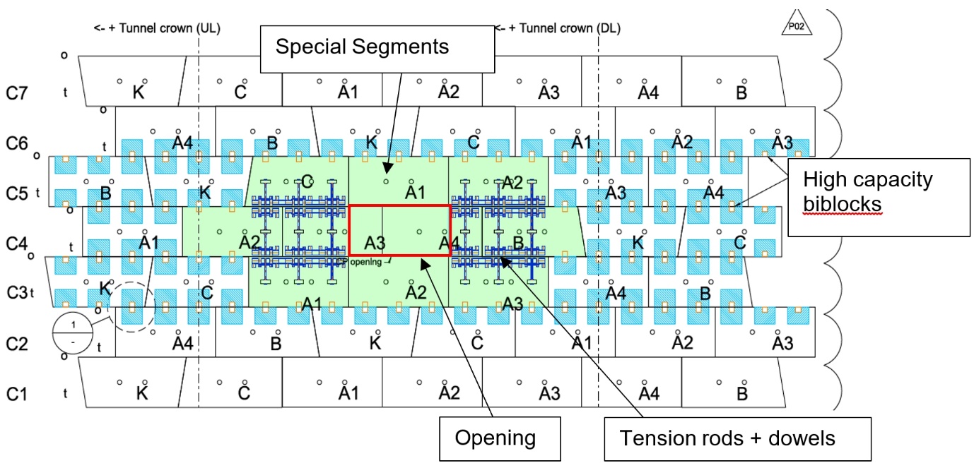
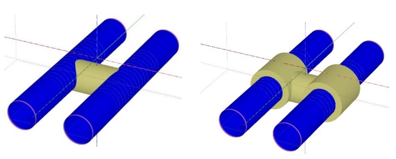
The connection sets are designed to generate a macrostructure of special segments plus additional high capacity shear dowels as shown below in figure 2:
DESIGN PROCESS
Ground load derivation from geotechnical models
The first step of the design was to obtain an estimate of ground loads acting on the structure. This step is of the utmost importance as it is the main load acting on the structure and it determines the asymmetry in the loads that govern the design.
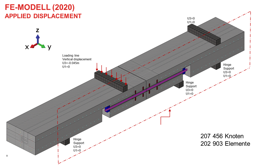
The ground load derivation has been estimated by means of geotechnical models using PLAXIS® 3D. The geotechnical finite element models had the purpose of deriving the worst load derivation and as such the following considerations were taken into account:
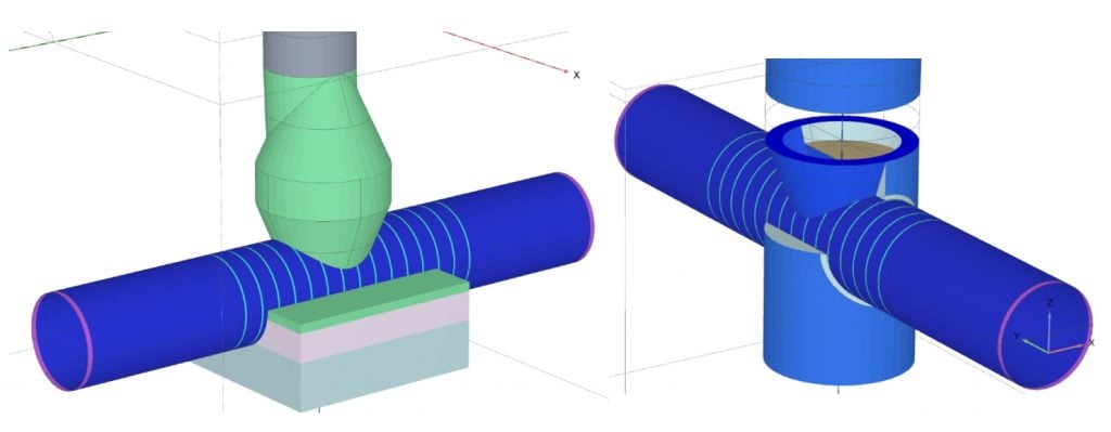
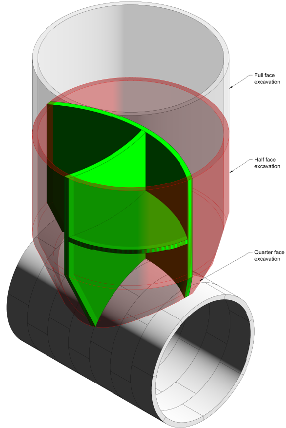
- Worst geometrical-geotechnical case scenarios. Different connections (including top connections, cross-passages and shaft-passages) were analysed in order to account for the worst loading conditions (Figure 3).
- Undrained ground behaviour for the London Clay and the Lambeth Group.
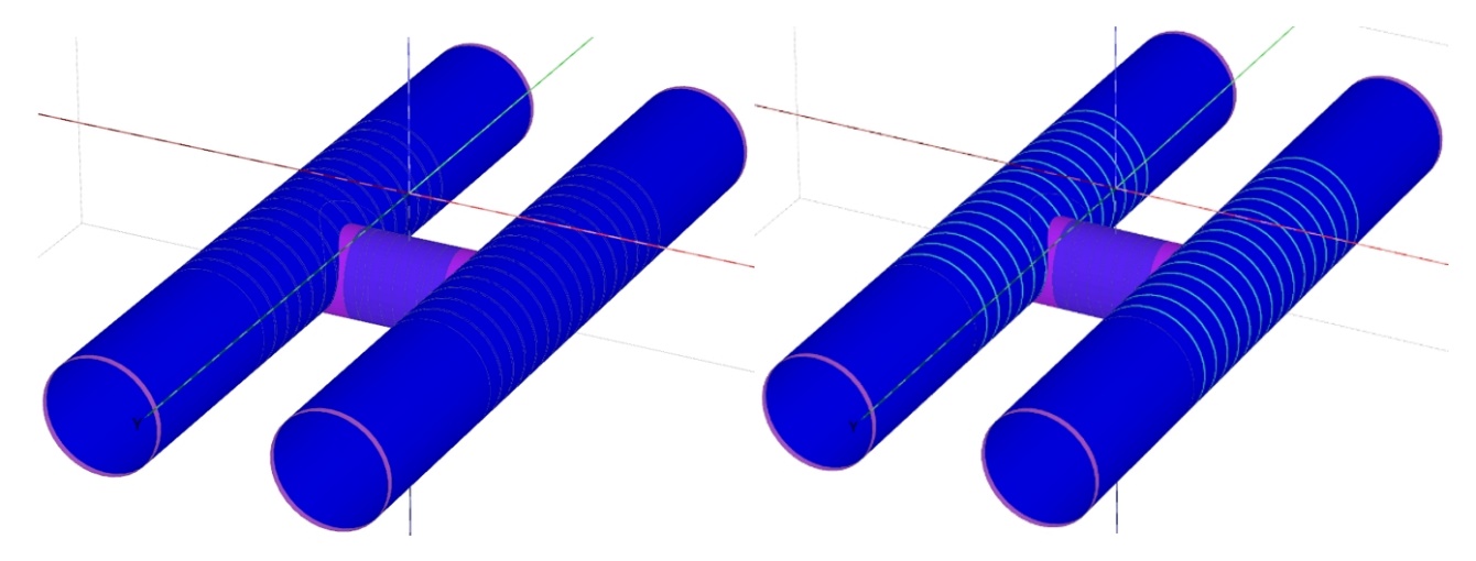
- Analysis of two extreme conditions: Tunnel modelled as a continuous tube and tunnel modelled with joints considered as hinged connexions with very low bending and shear resistance in radial direction (Figure 4)
- Different dewatering / depressurisation hypotheses (indicated in yellow in Figure 5) to find the most unfavourable load derivation.
- Both short-term and long-term conditions were considered.
From the model results, the stresses acting on the structure are obtained and imported to the structural models. Also, it must be noted that “in a spring-beam model, only the ‘active’ part of the ground pressure load should be applied onto the structure. The ‘passive’ part of the ground load is provided automatically by the springs” [1].
Therefore, the calibration of the structural model is an iterative process where the input active loads plus the obtained reactions are checked for compatibility to the stresses obtained from the geotechnical model.
Structural calculation of the member forces and stepping between segments
The considerations for the structural numerical models, carried out with SAP2000®, include:
- Staged construction
- Elastoplastic high capacity bi-blocks
- Elastoplastic tension rods with the design tension force
- Elastoplastic dowels
- Non-linear links between rings. Shear forces only act under compression. (Figure 6)
- Two hypotheses have been considered regarding the propulsion force between rings: a certain amount of the nominal TBM thrust remains in the segment; and no remainder TBM thrust is considered in the models.
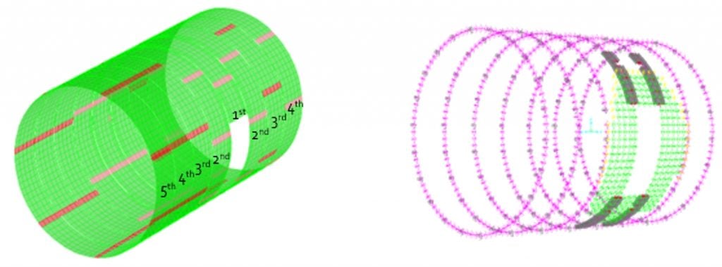
The capacity of the dowels between rings around the opening has been obtained with non-linear finite element models as shown below in figure 7.
The structural model calculation results show that:
- Tension rods are required around the opening in order to reduce the tension within the segments in the same area. This tension is mainly produced due to the longitudinal force.
- The tension rods and the residual propulsion force contribute to the shear transfer between the rings and the diagonally transferred hoop force, thus limiting the segment stepping.
- Staggered excavation of the adjacent cross passage or ventilation connection is a key point of the design in order to further reduce the steeping between segments and limit the internal forces in the segments during the construction (see figure 8).
Study of the construction compatibility with TBM advance
The design of the special segments was conceived so that it could be executed inside the TBM machine. Similar concepts have been used in cases such as the Koralm KAT2 Project in Austria.
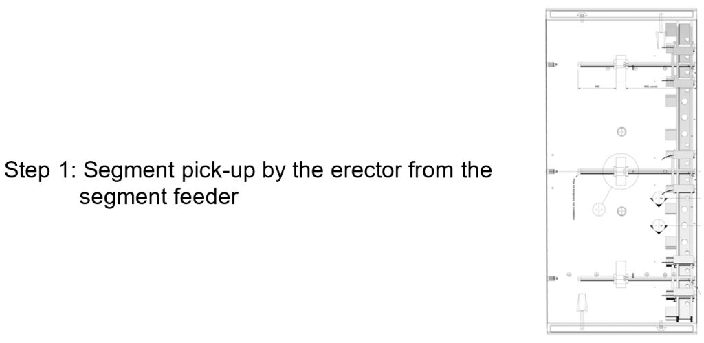
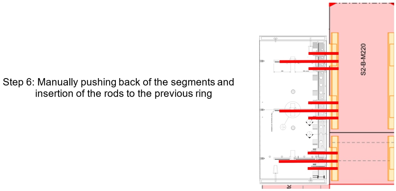
- The shear dowels will be installed into the previously installed ring following the removal of ram for installation of the following segments.
- The rods are inserted into the current segment being installed. Once segment is in position, the rod will need to be incrementally shifted back using grips/plyers via the connection pocket in the intrados into the previous ring to be fixed.
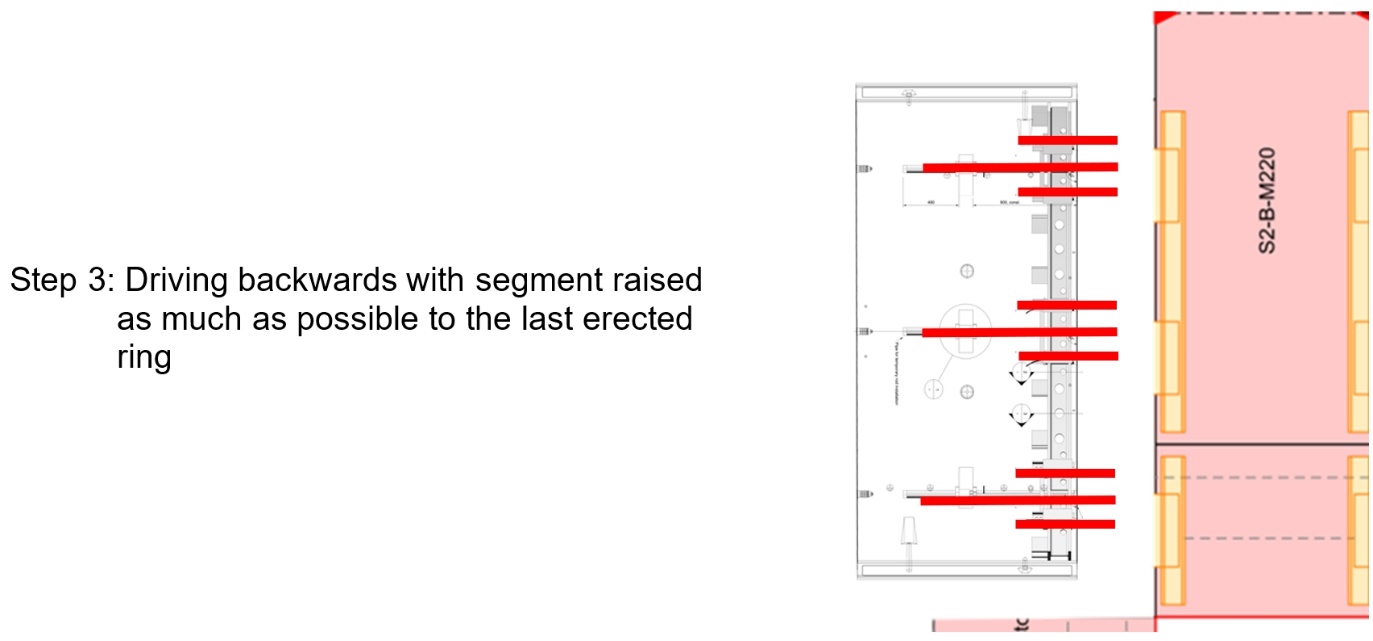
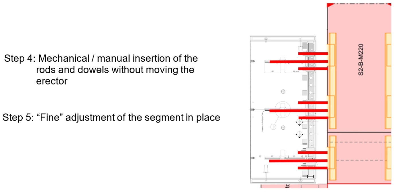
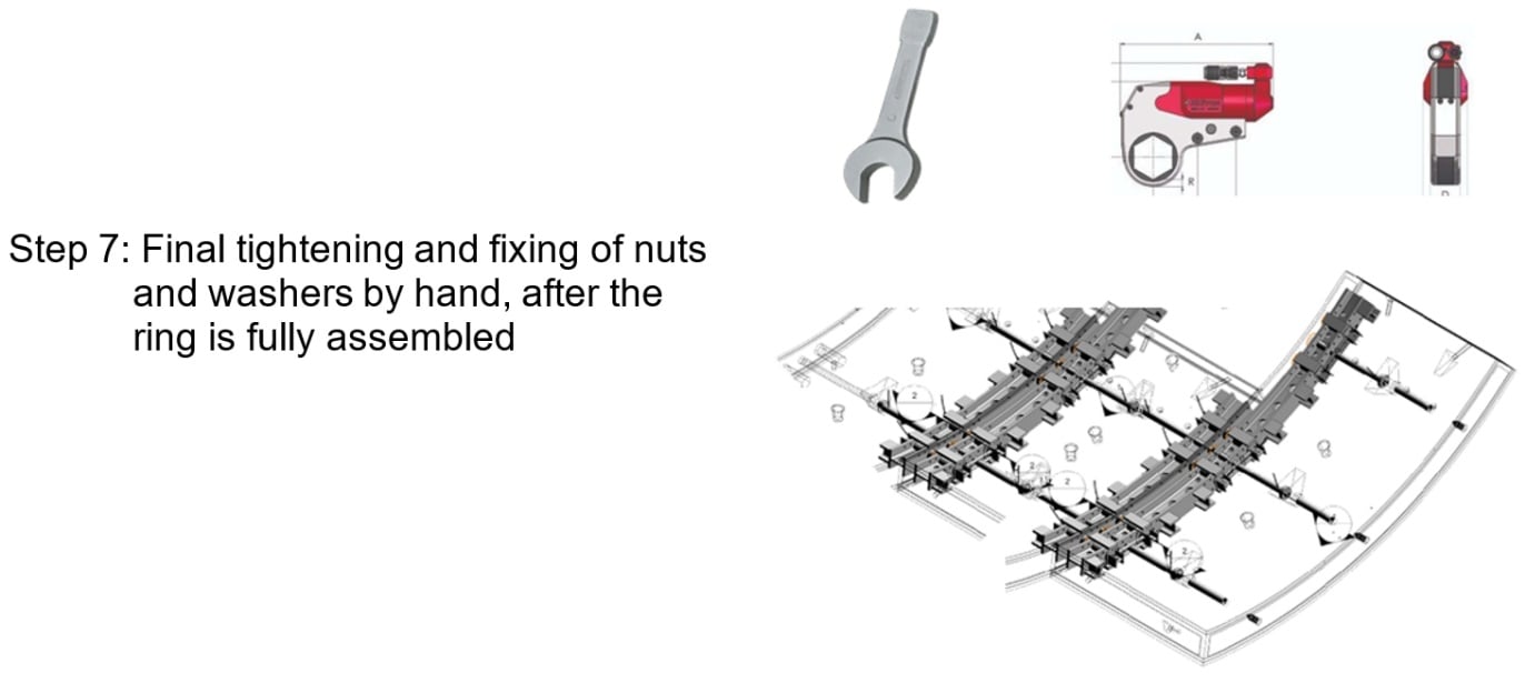
The ring installation consists of the following sequence:

Design of accurate tolerance of the embedded steel frames
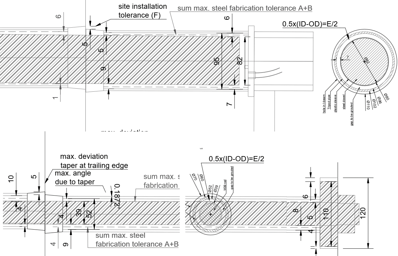
The embedded steel frames were also designed considering the tolerances of all the surrounding elements.
The image below, (figure 9), shows the worst case with all the maximum tolerances. The taper is at maximum, the green (dashed line) represents the maximum of all tolerances for steel fabrication and mould assembly disregarding that the maximum deviation is at maximum for the largest distance away from the ring joint (angular deviation). Additionally, a maximum offset for ring build is added. The green steel rod and the green steel dowel fit within the dashed green dashed lines
CONCLUSION
This innovative system using special segments achieves the goal of reducing the temporary works in the tunnel lining. It reduces construction works inside the tunnel and avoids temporary installations that may interfere with the development of all tunnel construction related works. Although some elements require manual installations, overall, the system has advanced a mechanically aided procedure of installing prefabricated special segments and improves safety during construction.
ACKNOWLEDGEMENTS
Special thanks to Skanska, Costain and Strabag (SCS JV) UK for their kind permission to reproduce some of the results studies that led to the current design solution for the Special Segments design.
REFERENCES
[1] Brierley, R. (2018) Design methodology for permanent complex structures: Secondary lining design of junctions. Crossrail Learning Legacy.
Peer review
- Vara Suntharalingam, Civil Engineering DirectorHS2 Ltd