Development of the Streethay Cutting Design: From Retained to Open Cut
Streethay Cutting is a 2.5km long cutting that lies approximately 1km to the east of Lichfield, Staffordshire. It is at the northern part of HS2 Phase One, beyond which the route continues north to Curborough where the route splits: the mainline interfaces with Phase Two; and a spur connects to the West Coast Mainline at Handsacre. Streethay Cutting was originally a retained cut at hybrid Bill. There were significant sections of diaphragm and secant piled walls up to 10m deep due to the quantity and control of groundwater, all of which would add significant capital cost and impact the programme. However, new GI data showed a greater proportion of mudstone versus sandstone across the length of the cutting, and additional groundwater monitoring data indicated more favourable groundwater conditions that are not hydrostatic from ground level. The updated ground model enabled the integrated project team (IPT) to have improved understanding of the groundwater infiltration rates, and to better understand some risks and uncertainties to be managed through detailed design.
This key information and further analysis have shown that a significant proportion of the cutting can now be changed from a retained cut to an open cut, removing the need for 1.2km of retaining wall. By reverting to the open cut, the design team Area North N1 N2 Design IPT has been able to realise significant cost and programme saving for HS2. This paper will cover the geotechnical constraints and challenges, as well as the wider issues that have been solved to change the design concept. The summary will include the environmental, sustainability and carbon savings, and some wider impacts made as a result of moving to an open cutting.
- Written by
-
Claire Howarth (BBV/Mott MacDonald)

-
Hannah May (BBV/Mott MacDonald)

-
Hitesh Mistry (BBV/Mott MacDonald)
- Resource type
- Resource type: Technical Paper
- Tags
- carbon posts
- Concrete Saving posts
- cutting posts
- groundwater posts
- Retaining Walls posts
- South Staffordshire Line posts
- Streethay posts
- sustainability posts
- West Coast Mainline posts
Context and Constraints
Streethay Cutting is part of the northern section of High Speed Two (HS2) Phase One – Lots N1 and N2 (Area North) including Long Itchington Wood Green Tunnel to Delta Junction and Birmingham Spur and the Delta Junction to the West Coast Main Line (WCML) tie-in, being delivered by the BBV Integrated Project Team.
Streethay Cutting is 2.5km long and crosses through predominantly undeveloped agricultural land, but interfaces with some significant infrastructure including the West Coast Mainline (WCML), South Staffordshire Line (SSL), A38 Rykneld Street, A38 Southbound Slip Road, and the realigned Cappers Lane highway. The cutting has six overbridges crossing it, and a significant culvert for the Fulfen Wood watercourse diversion. Another structure associated with the cutting is the Streethay Pumping Station, which collects track drainage at the low point in the cutting and pumps it to an attenuation pond before discharge. There is also a footpath and an Extra High Voltage Overhead (EHVOH) power cable that cross the cutting immediately north of the West Coast Mainline. Streethay Cutting is part the Area North works (N1 and N2 contracts) by the BBV Integrated Project Team (IPT).
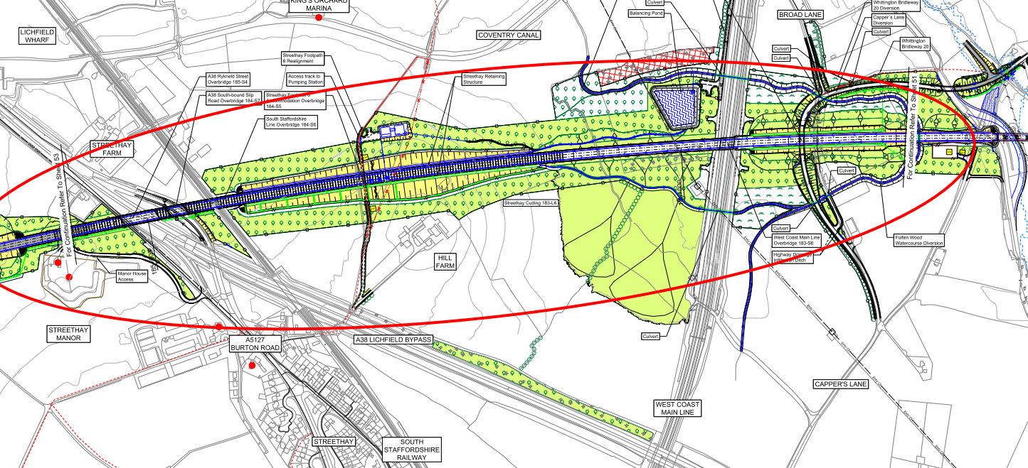
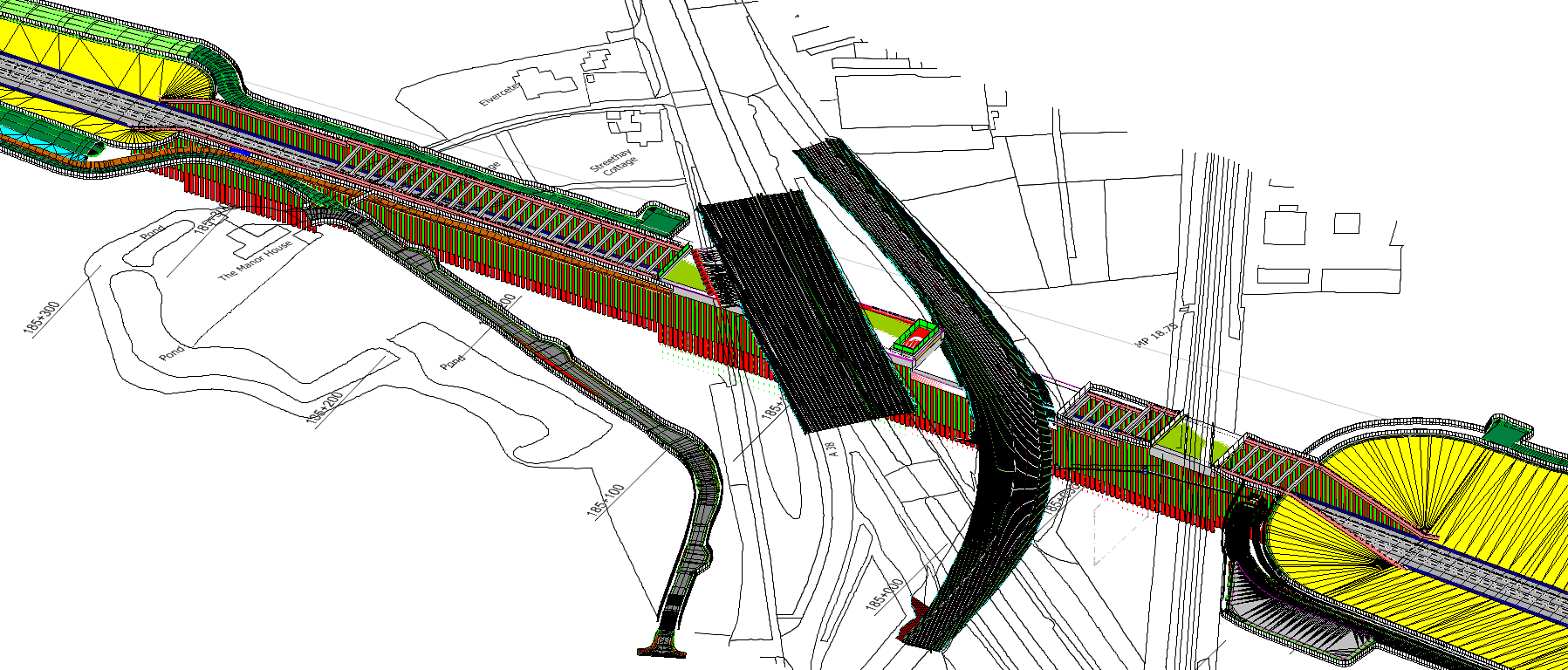
The extract of HS2 drawing C223-CSI-CV-DGA-030-225100-FPD[6] in Figure 1 below shows a significant portion of Streethay Cutting with the associated crossing assets.
The geology of the Streethay section of the route comprises a section of cutting within materials of the Mercia Mudstone Group (northern portion), and the southern section that is largely within the Helsby Sandstone Formation (part of the Sherwood Sandstone Group). The transition between the two groups within the cutting starts just north of the WCML. The nature of the geology and hydrology, coupled with the interaction with the existing infrastructure in the Streethay area, resulted in an alignment above ground in the original design, with HS2 crossing the Streethay area on embankments and viaducts. This above ground option was described in the November 2013 HS2 Environmental Statement [1] with further details provided in the Supplementary Environmental Statement and Additional Provision 2 (SES and AP2 ES) Environmental Statement[2]. In section 4.3.4 of the SES and AP2 ES[2], the information available at the time “assessed that the construction would result in an unacceptable level of disruption to the existing transport infrastructure” pointing to an above ground alignment.
Key stakeholders in the area include the Canal and River Trust, Network Rail, Staffordshire County Council and Lichfield District Council. Engagement with stakeholders, in particular with Lichfield District Council led to a preference of the route to pass under the local infrastructure. Further “technical work and subsequent ground investigation” (quoted from section 4.3.4 of the SES and AP2 ES[2])showed that a route could be constructed using retaining walls without having unacceptable levels of disruption. The commitment for HS2 to pursue the lower track alignment was recorded in an undertaking and assurance with Lichfield District Council (number 263[3], dated 9 October 2014). This resulted in the alignment being lowered by a maximum of 22.3m, and the creation of Streethay Cutting. The SES and AP2 ES[2] documents the updated scheme and environmental impacts.
The hybrid Bill design incorporating the 22.3m track lowering proposed to have 1.6km of the 2.5km cutting as a retained cut, with a maximum cutting depth of 22.7m. The design and construction of the cutting was on the critical path due to the construction programme required to build all the retaining walls, and the need to meet two rail blockades, the first of which was in May 2021 for the SSL. Five of the overbridges were single span integral bridges supported directly on the retaining walls, and the West Coast Mainline overbridge was a jacked box.
During scheme design, the IPT worked to understand the constraints that led the original designers to opt for a retained cutting. The key to unlocking Streethay Cutting and changing the design from a predominantly retained cut to an open cut, and thus deliver a design that could save significant cost and programme for HS2 was to understand the ground conditions and the groundwater. For the ground conditions, Mercia Mudstone and Helsby Sandstone are well documented, however the local transition at Streethay needed to be fully understood to see if alternative construction techniques could be employed. Regarding the groundwater, understanding the flow rates as well as the hydrostatic pressure from ground level was needed to consider removal of the retaining walls and move to an open cut solution.
Other key drivers for the IPT to look at an open cut methodology was to have a more sustainable design and reduce carbon. HS2 have set a 50% carbon reduction target on construction baselines for Phase One civil assets and removing retaining walls will contribute significantly towards that target.
Another factor in considering an open cut was to better integrate the cutting into the natural landscape and therefore help to realise the HS2 Design Vision[7]. Streethay is “Settled Farmlands” LCA (Landscape Character Area) with undulating lowlands and hills; agricultural land; network of narrow, winding lanes, clustered farmhouses; and small and medium sized hedged fields. The IPT felt that an open cut was in better keeping with the natural landscape character rather than a retained cut, and the open cut would help to better enhance the landscape as it interfaced with all the major infrastructure already present in the area.
Wider constraints that also fed into the design thinking included:
- South Staffordshire Water (SSW) have abstraction boreholes located near Streethay, and HS2 passes through Source Protection Zone 3, which is the total catchment area around a supply source that ends up at the abstraction point. SSW had concerns that the use of bentonite in constructing diaphragm walls would have a detrimental effect on water quality, particularly in relation to turbidity. Removing diaphragm walls, and hence the need for bentonite would help to allay their concerns.
- Limits of Deviation (LOD): The hybrid Bill sets out land limits for the permanent works of HS2 to be constructed. A retained cut can help to minimise the overall footprint of the railway but is expensive. An open cut could have a wider footprint but would need to be within the LOD.
Groundwater Assessment
Hydrogeological Overview
The HS2 Phase One hybrid Bill[8] (deposited Nov 2013, granted February 2017) preliminary design for the Streethay Cutting assumed that the base slab would be founded in mainly Bromsgrove Sandstone (now known as the Helsby Sandstone). With no data to confirm water levels, a worst-case groundwater condition of full hydrostatic pressure from ground level (in combination with potentially high permeability sandstone) led to significant sections of the cutting being designed as deeply embedded retaining walls to control groundwater (both in terms of pressure and potential ingress).
Two periods of ground investigation (including groundwater monitoring) were undertaken prior to the completion of scheme design:
- Oct/Nov 2017 – with monthly monitoring until July 2018;
- Nov/Dec 2018 – monthly monitoring to June 2019. This dataset formed the basis of the final scheme design ground model review, and subsequent groundwater assessment.
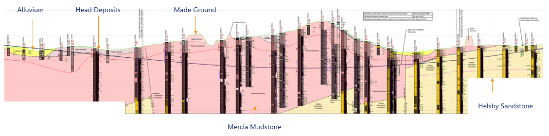
As indicated in Figure 2, the revised ground model indicated the majority of the asset to be underlain by bedrock of the Mercia Mudstone Group (Ch. 184+200 to Ch. 185+931), with the Helsby Sandstone Formation encountered only within the first 700m of cutting. Superficial Deposits consists of Head Deposits, Alluvium and Made Ground, that are intermittently deposited along the alignment with varying thicknesses (generally less than 5m).
The groundwater system influencing the engineering design of Streethay Cutting can be characterised as distinct hydrogeological domains – one dominated by the presence of the Helsby Sandstone Formation, and the other dominated by the Mercia Mudstone Group.
Groundwater flow within the Helsby Sandstone (formerly the Bromsgrove Sandstone) is characterised by a mixture of intergranular flow through weathered units, through to flow along shallow dipping bedding planes and via fracture network within unweathered bedrock (with occasional local confinement by intermittent mudstone horizons). Average permeabilities for the Helsby Sandstone across N1/N2 contract are approximately 5 x 10⁻⁶ m/s, with upper bound of around 6 x 10⁻⁵ m/s.
Classified as a Principal Aquifer, part of the cutting passes through total catchment area associated with South Staffordshire Water’s Trent Valley Pumping Station, located approximately 500m south-west of the alignment with groundwater abstraction from depth within the Helsby Sandstone. Abstraction from the Helsby Sandstone is likely to have led to a lowering in groundwater levels in the sandstone at depth, conceptually this may have led to the development of under-drained groundwater pressure profiles through the overlying Mercia Mudstone.
Geological faults have been identified leading to displacement of the Mercia Mudstone Group against the Helsby Sandstone Formation. Faults can act as barriers or conduits to flow depending on whether they connect two permeable strata (conduit) or juxtapose a lower permeability layer to a permeable one (barrier) and may have minor faults in parallel.
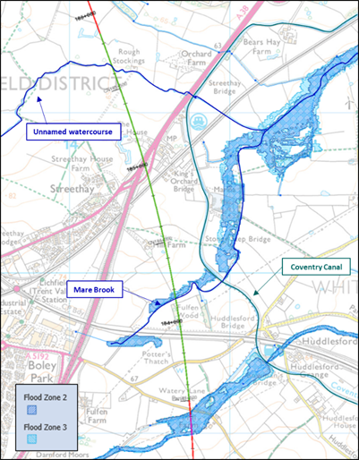
Recharge to groundwater is anticipated to be predominantly through rainfall infiltration, with limited natural rivers (Figure 3) present that are anticipated to be hydraulically connected to underlying groundwater at depth due to the presence of lower permeability superficial deposits, man-made nature (Coventry Canal), or lower permeability bedrock.
Conversely in the dominant Mercia Mudstone Group (MMG) area, the groundwater system is characterised by an upper completely weathered, cohesive Grade IV mudstone aquitard (with lower permeability), overlying a partially weathered transition zone (Grade III) of relict fractures and bedding planes. With unweathered Grade I / II MMG at depth characterised by flow predominantly along fractures, and occasional interbedded sandstone beds (Figure 4).
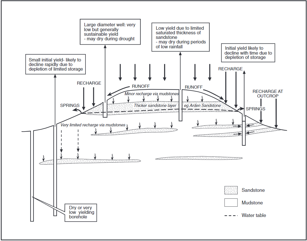
With reduced rainfall infiltration (leading to perched waters above Grade IV aquitard), the heterogeneous vertical nature of the MMG can potentially result in multiple water tables. Average permeability for the MMG Grade I/II is approximately 3 x 10⁻⁷ m/s, with an upper-bound of 9 x 10⁻⁶ m/s (with potential for local more permeable fractures).
Groundwater Levels
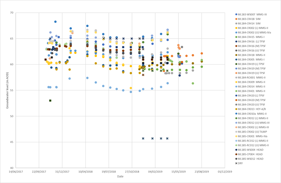
With an improved groundwater monitoring data set (laterally, vertically and temporally) collected between 2018 and 2019 (Figure 5), the heterogenous nature of the groundwater system (from superficial deposits to bedrock) is reflected in groundwater levels ranging from 56m AOD to 69m AOD (with seasonal influence of approximately 1m to 2m). This variability is illustrated in Figure 5 showing a large range and spread of data.
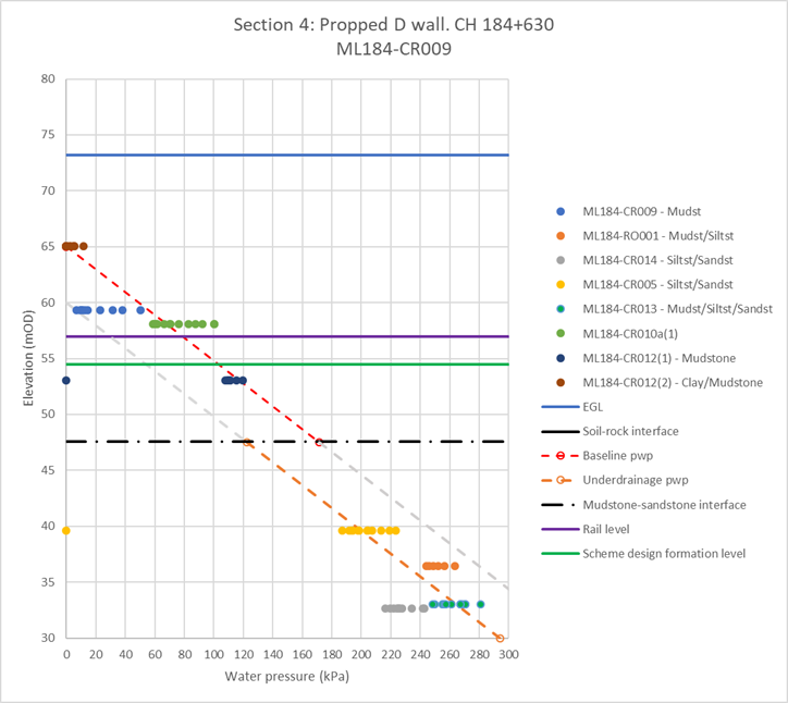
Plots of groundwater pressures in areas where faulting has reduced the thickness of Mercia Mudstone (though uplift) shown potential underdrainage influence of groundwater abstraction from the Helsby Sandstone aquifer at depth (Figure 6). In addition to indicating groundwater levels significantly lower than ground level, which equates to lower potential groundwater pressures than may have been assumed for preliminary design.
Longitudinal plot of minimum / maximum groundwater levels versus HS2 rail level (Figure 7) illustrates that for the majority of the Streethay cutting, groundwater level may potentially be only 1m to 2m higher than rail level (~10 – 20 kPa) – or potentially dry or just perched waters.
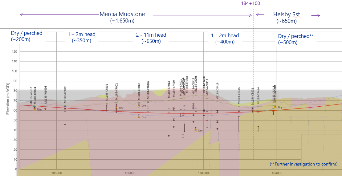
In the area of the Helsby Sandstone, further investigation (including additional drilling, monitoring and pumping test) are planned to characterise this area and qualify potential risks.
In the deepest section of the cutting, a wide range in potential groundwater levels is recorded (between 2m and 11m above rail level) albeit significantly lower than preliminary design, and in a potentially lower permeability material.
The lower groundwater levels (when compared to preliminary design), in combination with the asset dominated by the Mercia Mudstone Group, led to an initial review of groundwater ingress for open cut scenario to determine if potential rates may be practically controlled through standard drainage measures in the long-term.
Groundwater Ingress Assessment
The potential range (due to permeability variation) of long-term groundwater ingress that may enter the basal drainage system (Figure 8), was estimated for one metre long 2-D sections of cutting (l/s/m) then conservatively scaled up across longitudinal sections of the cutting. The cumulative estimate of groundwater ingress was then broadly compared to the overall capacity of the drainage network and pumping station. This assessment was undertaken utilising both an analytical approach (Figure 9), and numerical modelling (steady state SEEP/W) of two deepest cutting sections in the Helsby Sandstone (Ch. 184+000) and MMG (Ch. 184+500) for comparison.
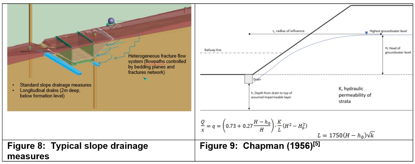
The steady state analytical solution utilised was for a partially penetrating linear slot with flow from line source on both sides. This represents a conservative estimate of ingress due to the assumption of a homogeneous, isotropic aquifer with no consideration of variation in permeability (vertically or laterally) associated with heterogeneous nature of Helsby Sandstone / Mercia Mudstone Group. In addition, the maximum groundwater level (62m to 64m AOD) across a defined chainage was utilised.
Steady state numerical modelling was also undertaken for comparison to analytical results (with sensitivity check for higher groundwater levels set at one metre below ground level). Table 1 presents a summary of the analytical (and numerical model) assessment estimates.
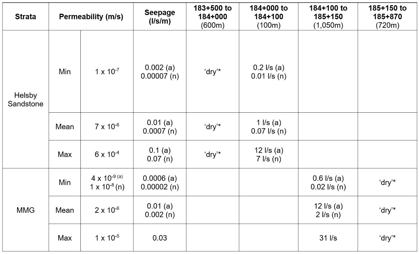
Using average permeability values, less than 20 l/sec across the cutting was estimated analytically (up to 36 l/s when maximum permeability values used throughout). Numerical modelling estimates suggested potentially less than 10 l/s ingress across the cutting.
Compared to a pumping station capacity of approximately 1,500 l/s it was felt that potential long-term groundwater ingresses to an open cutting would be manageable with standard groundwater control / slope drainage techniques.
This is be subject to further ground investigation to quantify localised areas of uncertainty where gaps in the groundwater monitoring data set exist, and detailed review of geology (particularly fracture networks and sandstone beds) to identify potential for higher localised groundwater flows.
Retaining Walls
Early Scheme Design
The initial scheme design was a retained cut similar to the hybrid Bill design as a fuller understanding of the geology and hydrology had not been made. The initial design of the wall was approximately 1600m long, retaining heights of up to 10m approximately made up of the wall configurations in Table 11 below.
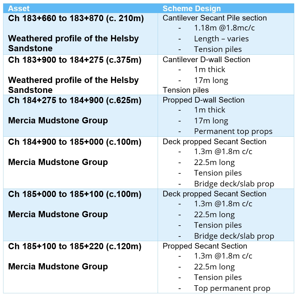
Particular aspects of this design that influence the choice of piling include:
- The use of secant piling for the southern and northern sections was primarily driven by construction sequence and site constraints.
- Towards the southern end, HS2 passes under the WCML. A jacked box solution is proposed at this location, and piling is required to be done in advance in order to construct the box. Site constraints meant that it was neither feasible nor economic to establish a bentonite plant for diaphragm walling.
- At the northern end of Streethay Cutting, there are three integral bridges in succession for the SSL, A38 Rykneld Street and A38 Southbound Slip Road. The very tight possession window for the construction of the SSL overbridge meant that large diameter secant piling was preferred.
- The Ground investigation information indicated that the long-term water table was typically towards the top of the or above the top of the retaining wall with section of the slopes being designed as wet cuttings. As a result of this a base slab with tension piles was required. Tension piles were used to minimise both the slab depth and connection requirements at the walls. Small diameter rotary bored piles installed from formation level were preferred by the contractor.
- In the hybrid Bill design, the pumping station and wet well were located adjacent to the low point of the track but at the top of the cutting. This meant that a deep shaft was needed to satisfy the storage requirement below track level and would have required a directional drilled or micro TBM (Tunnel Boring Machine) connection between the shaft and the track drainage. For scheme design, the wet well was relocated adjacent to the retaining wall with the pumping station located directly over it, which removed the need for a piped connection and reduced the depth of shaft required. A rising main adjacent to the top of the retaining wall carried flows to the balancing pond located towards the southern end of the wall.
Final Scheme Design (Consolidated Design)
The work to better understand the geology, groundwater flow rates and hydrostatic pressures described above was pointing towards an open cut solution. However, there were other design changes made to facilitate the reduction in retaining walls at Streethay that helped to reduce cost and programme, and to provide a more sustainable engineering solution.
A slope optimisation study carried out across the contract concluded that the 1v:3.5h slopes used for the Streethay retained cutting (slopes from the top of the retaining walls to ground level) could be steepened to 1v:3.0h. This combined with EDC061 (Engineering Directorate Communication), concerning the reduction in the width of the open walking route to the functional cross section resulted in changes in geometry that was sufficient to allow the main retaining wall to be removed for a significant length (1.2km) with sheet piles provided at the top of the slope locally at pinch points to maintain the required width for maintenance access, land drainage and fencing.
The remaining portion of retaining wall, approximately 420metres in length was at the northern end where the alignment passes under the SSL and A38. The LOD is very constrained and trying to minimise any disruption to the existing infrastructure, it was impossible to have an open cut through this section. For these remaining retaining walls, from approx. Chainage 184+900 to +185+220. the walls will be constructed top down, with the integral bridges to be completed with traffic flowing before excavation to formation level is complete. Refer to Figure 10 showing an extract of the federated model.
Installation of tension piles for the base slab would require the use of limited headroom rigs which would mean slower installation. The construction programme would also be affected by the preparation of the pile heads, in order to use small diameter piles the sections were heavily reinforced making the pile slab connection congested.
There is also the risk of long term swelling which would mean that the slab and connections to the secant pile walls would have to be designed for additional forces. Connections into secant pile walls have limited capacity and catering for these forces could be difficult. Therefore, further analyses using Plaxis[9] was carried out to determine whether the base slab could be removed completely. The results of the analysis confirmed that the base slab could be removed completely, and that the HS2 slab tack formation could be built directly on the ground within the retaining walls.
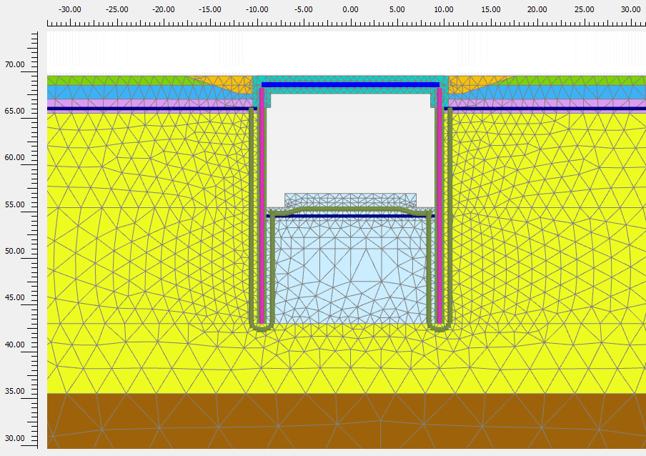
The open cut design at Streethay required deeper drainage trenches adjacent to the retaining walls, and therefore the female secant piles had to be deepened from initial scheme design to avoid any risk of soil loss through the piles during drainage installation. The effect of the drainage trenches was also included in the Plaxis model, with and image shown below in Figure 11. The image shows the general arrangement within the ground model, including the retaining walls and prop at the top. The construction sequence was incorporated into the model, which helped to confirm the length of both the male and female secant piles.
Streethay Pumping Station
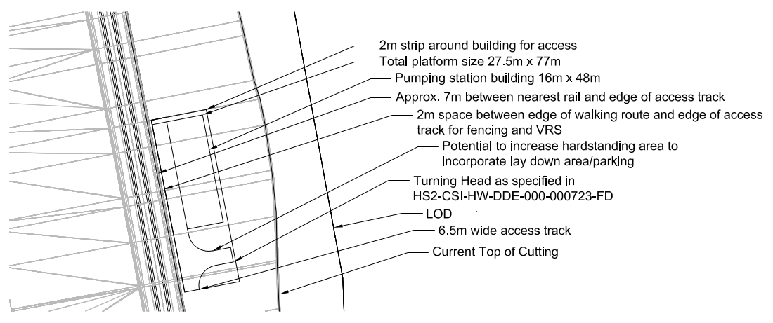
With the removal of the retaining wall adjacent to the pumping station, the pumping station design had to be reconfigured. It was relocated to track level with sufficient room available for a maintenance access running adjacent to the railway and up to the balancing pond. For efficiency the wetwell has been located underneath the pumping station building to take advantage of the building’s weight to resist uplift forces due to the water table. To minimise the length of the rising main required from the wetwell, it was routed directly up the cutting behind the building into a discharge chamber and can then fall by gravity to the balancing pond. Refer to Figure 12 for the Pumping Station General Arrangement.
Environment, Sustainability and Carbon, and Wider Benefits
Environment, Sustainability and Carbon
The adoption of the open cut opportunity is underpinned by the three pillars of sustainability: social, economic and environmental. Many of the savings realised by changing to a predominantly open cut cover more than one aspect as the three pillars are not separate but interlinked.
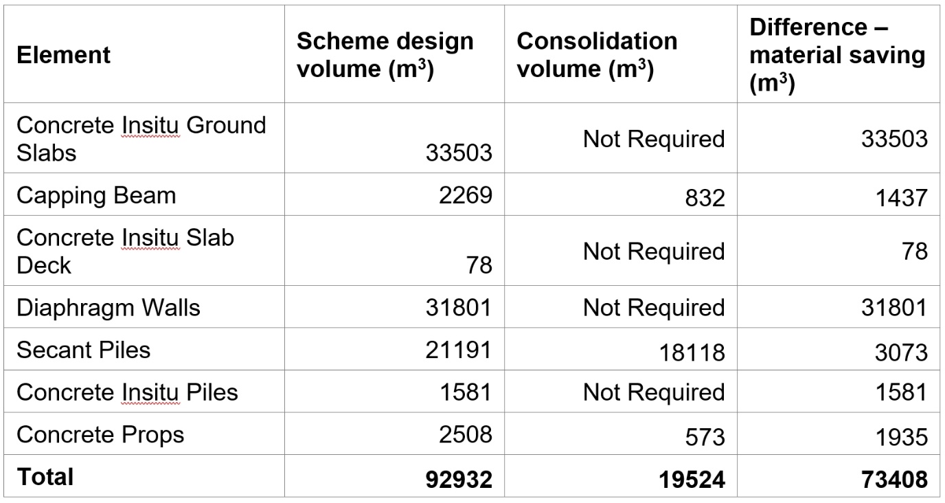
The removal of all but one 420m section of secant piled wall has clear economic benefits with significant saving (in the £millions) in construction costs. The cost savings arise from a reduction in programme of up to a year, reduced use of specialist piling equipment, reduction in preliminary costs and directly from material savings. Table 3 below shows the difference in concrete volume between the retaining wall at initial scheme design, and after optimisation during consolidation (final scheme design). The amount of concrete used has been reduced by approximately 79%. This reduction in concrete volume directly results in a reduction of carbon emissions from the production and transportation of the concrete as well as the significant material saving itself.
In addition to the direct material and carbon savings from the reduction in concrete, there is an overall reduction in vehicle movements despite the additional vehicle movements required to excavate a larger amount of material for the open cut. There is also an indirect reduction in vehicle movements caused by using only secant piles for the remaining retaining walls, as equipment required to support bentonite holding and circulation equipment for diaphragm walls is not required.
A further benefit is that the reduction in vehicle movements, reduced equipment on site and reduced number of secant piles required to be installed by the specialised secant piling rig will all contribute to a reduction in construction noise, ensuring that construction has less of an impact on the surrounding rural community and is a better working environment for construction workers.
The adoption of an open cut does, however, increase the amount of material required to be excavated for the cutting. This was part-mitigated by adopting 1v:3h slopes for the open cut (the retained cutting slopes were 1v:3.5h) and part-mitigated by reviewing the landscape design in Streethay Cutting so that the extra excavated material could be used for landscape mitigation. The adoption of a ‘less engineered’ approach is more sympathetic and in-keeping with the local rural landscape (Streethay is “Settled Farmlands” LCA) and makes integration easier, especially in the central section of the cutting where no landscape earthworks are proposed.
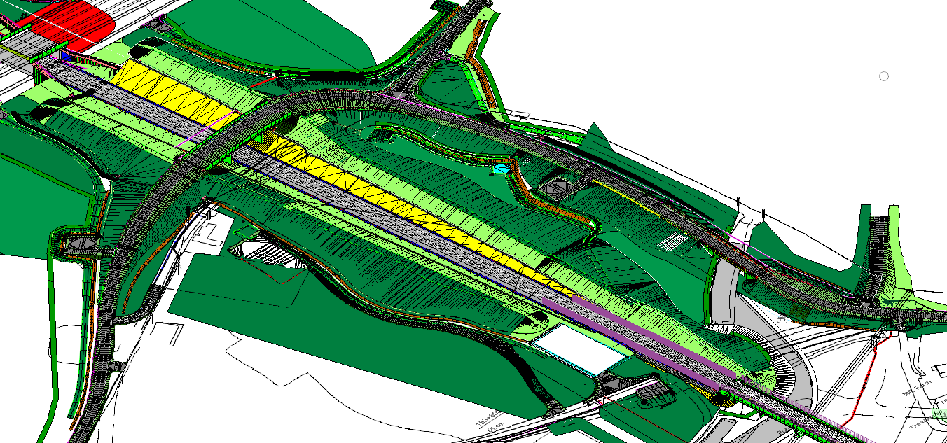
One area that has particularly benefitted from this sustainable use of material is the Cappers Lane highway realignment (shown in figure 13 below). The realigned highway is on a raised embankment to ensure acceptable clearance over HS2, so a significant amount of work has been completed after the removal of the retaining walls to fully integrate the raised highway and landscape earthworks in the area. The landscaping begins to the south of the WCML embankment and terminates at Cappers Lane Auto Transformer Station (ATS) on the west, and at Cappers Lane Viaduct on the east. The earthworks continue further south on the east side to improve the view post-scheme from the diverted and extended Wyrley and Essington Canal.
Health and Safety Benefits
Moving to an open cut has realised significant Health and Safety benefits:
- Removing the retaining walls under the EHVOH line (400kV) close to the WCML has eliminated the risk of touch potential by piling rigs working underneath.
- The optimisation of the retaining walls has made the construction simpler and safer by eliminating the ground slab in the remaining secant piled section. Hence there is no need for a connection detail that may have been required to be completed manually causing a risk to the operative from hand arm vibration.
- The removal of diaphragm walls completely eliminates the need to use bentonite, mitigating a number of health and environmental risks such as bentonite groundwater pollution.
CSM (Common Safety Method) for operational railway safety
From a CSM perspective, an open cut is much safer than a retained cutting as maintenance of an open cut, especially one with gentle 1:3 slopes is much simpler than that of a retaining wall of varied type. In case of an emergency, egress from track is much safer and ramped emergency access points to allow passengers to escape the retaining walls are no longer necessary.
Wider Benefits
The removal of the diaphragm wall has a positive impact on so called ‘crossing assets’. It has reduced the complexity of construction for Streethay Footpath 6 Accommodation Overbridge and Capper’s Lane Overbridge. These overbridges were to be single span structures integral with the retaining walls, which led to difficulties in terms of construction sequencing and maintenance of the retaining walls and props post-scheme. The structures are now to be concrete three-span integral overbridges with shallow foundations.
Summary and Conclusion
Streethay Cutting is a complex area with significant existing infrastructure and challenging ground conditions. The IPT working in the area has taken time to understand all the constraints and issues to deliver a sustainable open cut design that is better in keeping with the local landscape and achieve HS2’s Design Vision in keeping with the core design principles of People, Place and Time. In addition, the design work has resulting is significant cost and programme saving resulting in a major benefit to the UK Taxpayer.
Acknowledgements
Thanks to the wider IPT for contributing to the design and delivery of Streethay Open Cut.
References
[1] London-West Midlands Environmental Statement Volume 2 Community Forum Area report CFA22 Whittington to Handsacre November 2013
[2] High Speed Rail (London – West Midlands) Supplementary Environmental Statement and Additional Provision 2 Environmental Statement Volume 2 Community forum area report CFA22 Whittington to Handsacre July 2015
[3] Commitments Compliance Register (Works Information 310) N2 Document Number: 1MC09-BBV-AU-REG-N002-000001. The U&A 263 text is: The Promoter will promote an additional provision which will provide for the lowering of the railway so as to cross beneath the A38, the South Staffordshire Railway and West Coast Main Line and subject to the approval of Parliament, the Promoter will require the nominated undertaker to construct the works in accordance with the additional provision. In preparing the additional provision, the Promoter will keep Lichfield District Council informed of the progress of the design of the revised alignment and consult them on any material changes to the design.
[4] Extract from British Geological Survey, 2000, Figure 7.13. The physical properties of minor aquifers in England and Wales. Technical Report WD/00/04
[5] Chapman (1956); in Mansur and Kaufman (1962) from CIRIA 570 Groundwater Control: design and practice, 2nd ed. (2016).
[6] C223-CSI-CV-DGA-030-225100-FPD P02 Plan of Route Country North – General Arrangement Permanent Works Sheet 52.
[7] HS2 Design Vision April 2017 Published by High Speed Two
[8] HS2 Phase One: High Speed Rail (London to West Midlands) Bill Published 25 November 2013 from High Speed Two (HS2) Limited
[9] Plaxis is a computer program that performs finite element analyses within the realm of geotechnical engineering.
Notation
AOD – Above Ordnance Datum
Area North N1 N2 Design IPT – Mott MacDonald Systra Design Joint Venture: Integrated Project Team responsible for the scheme and detailed design of the northern portion of HS2 Phase 1 from Leamington Spa to Birmingham and up to Curborough and Handsacre.
ATS – Auto Transformer Station
CFA Community Forum Area
EDC – Engineering Directorate Communication
EHVOH – Extra High Voltage Overhead
ES – Environmental Statement
FPD – Final Preliminary Design
HS2 – High Speed Two Limited
IPT – Integrated Project Team
LCA – Landscape Character Area
LOD – Limits of Deviation
MMG – Mercia Mudstone Group
SES and AP2 – Supplementary Environmental Statement and Additional Provision 2
SSL – South Staffordshire Line
SSW – South Staffordshire Water
TBM – Tunnel Boring Machine WCML – West Coast Mainline
Peer review
- Nick Sartain, Head of Geotechnical EngineeringHS2 Ltd
- James DudfieldEDP(Jacobs)