Temporary access road optioneering and cost analysis
High Speed Two (HS2) Lots C2 and C3 covers a section approximately 80km long between the Chilterns and Warwickshire. To enable construction of these sections, it was identified that a temporary service road would be required along the length of the HS2 route.
An optioneering study was commissioned aiming to reduce construction costs of this element. This included the analysis of four different forms of road construction – two asphalt/concrete surfaced and two unsurfaced compacted granular material. In addition, an alternative fifth option was proposed inspired by treatments applied to granular roads in developing countries, which consists of a traditional temporary granular road with 20 mm of bitumen surface dressing.
Each type of construction was trialled and compared both for use on a subgrade of CBR 1% and a subgrade of CBR 2.5%. The findings of the paper show that the asphalt and concrete surfaced roads were most expensive to install but also most robust in both conditions. The unsurfaced granular road constructions were shown to be more expensive in the long run when accounting for maintenance costs compared to the newly proposed bitumen surfaced dressed option. The alternative bitumen surfaced dressed option also had several benefits over the unsurfaced granular constructions, such as a more skid resistant surface, lower dust pollution, higher possible longitudinal gradient, allowance for road markings and easier control of surface water run-off.
The study recommended the fifth option of surface dressed granular road. The balance of properties lends itself very well to a site access road that is temporary in nature but will extend for a long distance, be in place for a longer period of time and will undergo a significant number of axle passes. It is the lowest in cost out of all the proposed options but also retains many of the benefits of the more expensive heavy-duty access roads.


Introduction
This paper focuses on the central section of High Speed Two (HS2) Phase One – Lots C2 and C3 – which includes the North Portal Chiltern Tunnels to Brackley and Brackley to South Portal of Long Itchington Wood Green Tunnel. These are the responsibility of the EFKB Integrated Project Team.
A rail project the length and scale of HS2 has very high demands on temporary works. Site compounds and plant access roads will be required across a huge length of the country. On a project of this size, the choice of pavement construction for site access roads could have huge implications on cost, sustainability and safety.
The site access roads are an important element of the compounds and Kier Professional Services (KPS) were tasked with optioneering against four different traditional forms of pavement construction. This provided an opportunity to evaluate the pros and cons of each form of construction not just specifically for use on HS2, but for use on any infrastructure project that requires large lengths of access road for extended periods of time.
The criteria that the different forms of construction will be compared against include the following:
- Cost
- Ease of installation
- Maintenance requirements
- Sustainability
- Environmental impact
- Safety
- Restrictions on use
Each form of construction has been evaluated for use on a subgrade of 1% CBR and 2.5% CBR to account for the potential variety in ground conditions where the access roads could be required.
Assessment
The initial design brief requested design thicknesses for two types of construction on subgrades across CBR values ranging from 1% to 5%. The pavement options specified were as follows.
- Flexible asphalt pavement with granular foundation
- Rigid roller compacted concrete (RCC) with granular foundation
A further design brief requested the development of a granular unsurfaced road option on subgrades with CBR values of 1% and 2.5%. The two proposals were as follows.
- Granular road build-up (unsurfaced)
- Lime stabilised build-up with a granular wearing surface
All options were compared using designs suitable for 1 msa.
Upon receipt of the second design brief, KPS also proposed and evaluated a fifth option for the pavement construction. This option consists of a granular road build up with 20mm bitumen surface dressing. This proposal was inspired by treatments applied to granular roads in developing countries [1]. The newly proposed form of construction was thought to combine the low cost of the granular roads with the safety and low maintenance benefits provided by the more expensive finished options. A temporary access road that will be heavily used over a long period of time (such as during the construction of HS2) may be best suited to a hybrid between a standard low traffic temporary access road and a standard permanent form of construction.
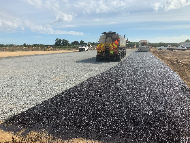
The different forms of construction were preliminarily designed for required depths and makeups using relevant codes and standards that will be listed in the following sections of this paper. Guidance in codes and standards were also followed for the qualitative criteria such as safety and maintenance requirements. Finally, a cost comparison table was put together estimating the costs against each form of construction (see Table 1 and Table 2 for detailed breakdown). KPS worked collaboratively with Ayton Products (a division of Kier Highways) for the design and cost estimate of the newly proposed surface dressed option. See a photograph of the trials undertaken as part of the analysis in Figure 1 below.
Flexible asphalt pavement with granular foundation
Flexible asphalt pavement is a widely used form of construction commonly implemented on permanent roads. The surface layer is comprised of a mineral aggregate bound with viscous bitumen. It is suitable for high volumes of traffic and has a design life exceeding what is required for this project. The asphalt is typically installed on top of a granular base layer.
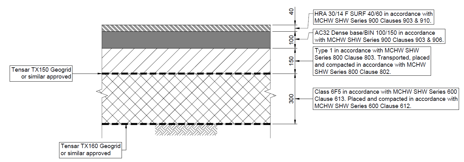
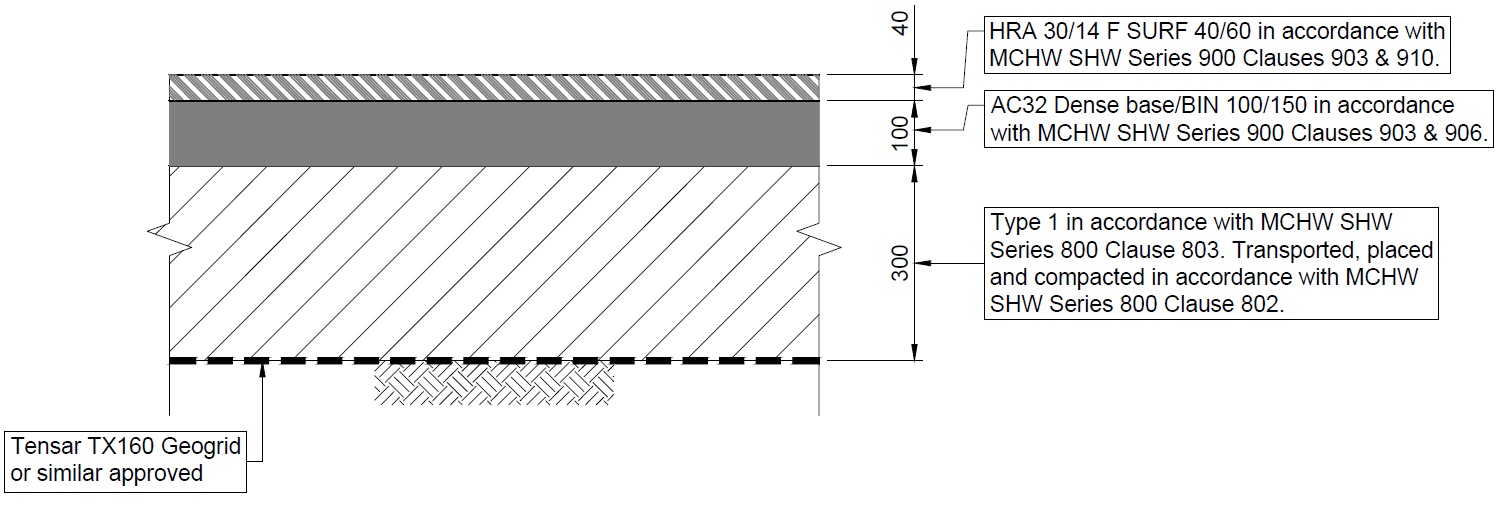
The construction considered in this comparison consists of a minimum of a base layer of geogrid, a layer of compacted type 1 granular material, a layer of dense base course and a finishing layer of HRA. On a subgrade of 1% CBR an additional layer of geogrid and compacted 6F5 granular material is required immediately on top of the subgrade.
The design of the flexible asphalt pavement with granular foundation has been designed in accordance with recommendations listed within the following design standards:
- DMRB IAN 73/06 Design guidance for road pavement foundations (DRAFT HD25) [2] (now CD 225 – Design for new pavement foundations) [3]
- DMRB HD26/06 Pavement Design [4] (now CD 226 – Design for new pavement construction) [5]
- TRRL RN29 [6]
- TRRL LR1132 [7]
Geogrid reinforcement has been incorporated in the design and the Tensar pave software has been used to determine construction thicknesses and geogrid types required. See figures 2 and 3 for build-ups on subgrades of 1% and 2.5% CBR.
Some of the key features of this form of build-up that make it so popular in permanent road-ways is the high skid resistance and potential running speeds it offers. This construction places above all the other options when considering these criteria, but suffers from a longer construction time, and is also more difficult to reuse/recycle at end of life. Please see table 3 in cost estimate breakdown and properties comparison section for further details.
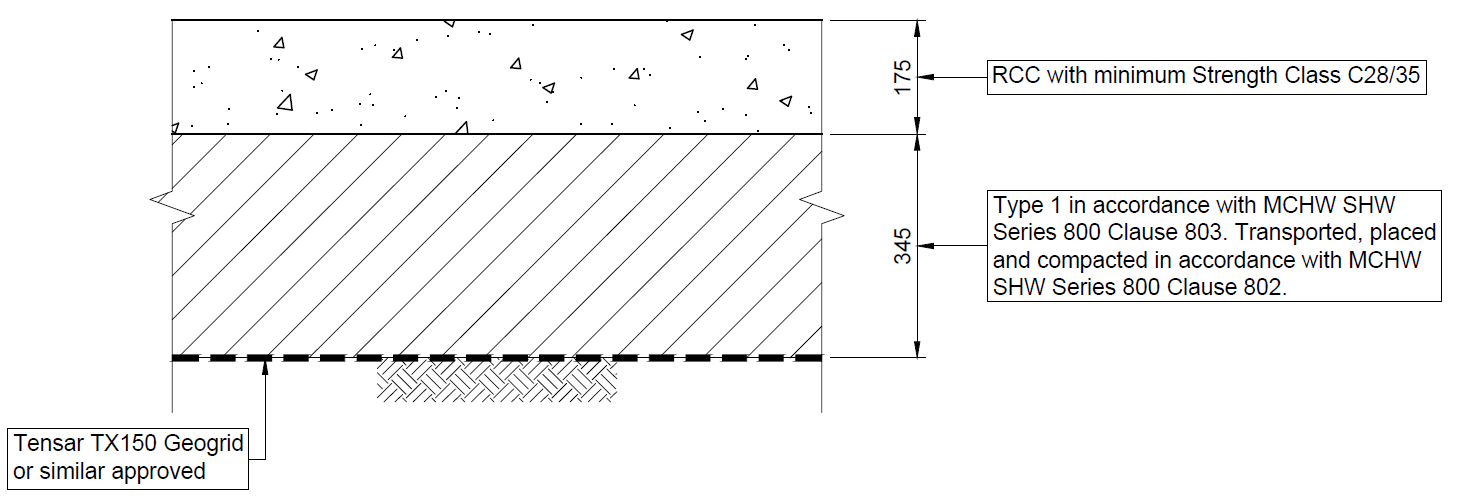
Rigid roller compacted concrete (RCC) with granular foundation
RCC pavements are typically used to surface permanent roads that are likely to experience heavy or specialised loads, such as at ports or industrial yards. It is placed in a similar way to asphalt pavements using similar modified equipment, then compacted with rollers. The mix resembles usual construction grade concrete but is generally drier to ensure stiffness during compaction. It is typically constructed without joints and left unfinished resulting in fast construction times and simple installation methods. RCC pavements do not require formwork or reinforcement. The RCC is typically installed on top of a granular base layer [8][9].
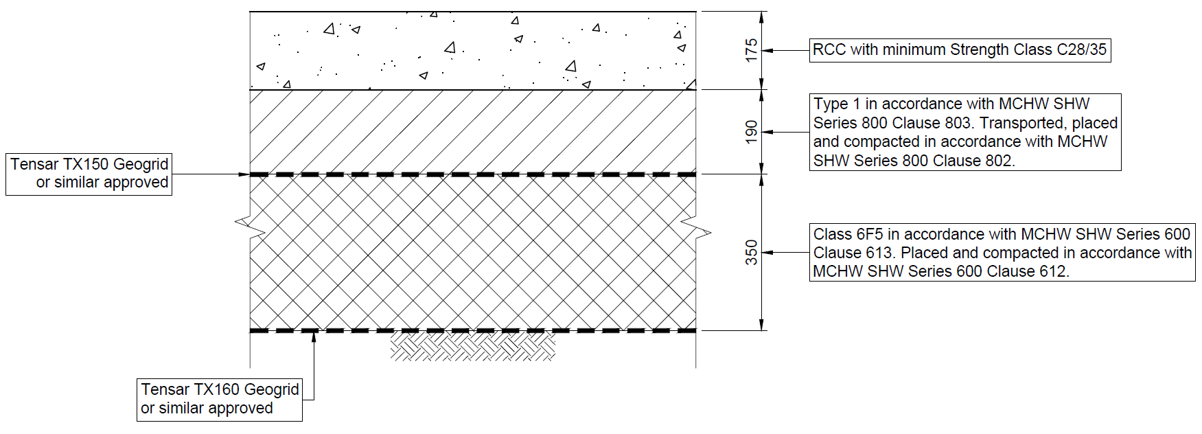
The construction considered in this comparison consists of a minimum of a base layer of geogrid, a layer of compacted type 1 granular material and a layer of RCC. On a subgrade of 1% CBR an additional layer of geogrid and compacted 6F5 granular material is required immediately on top of the subgrade.
The design of the RCC pavement with granular foundation has been designed in accordance with recommendations listed within the following design standards:
- DMRB IAN 73/06 Design Guidance for Road Pavement Foundations (DRAFT HD25) [2] (now CD 225 – Design for new pavement foundations) [3]
- TRRL LR1132 [7]
Geogrid reinforcement has been incorporated in the design and the Tensar pave software has been used to determine construction thicknesses and geogrid types required. See figures 4 and 5 for build-ups on subgrades of 1% and 2.5% CBR.
One unique benefit to this form of construction is the strength of the concrete in the top layer. It is capable of spanning local weak spots in the ground and sub-base. The higher albedo value also results in reduced heat island effects and lighting requirements. Please see table 3 in cost estimate breakdown and properties comparison section for further details.
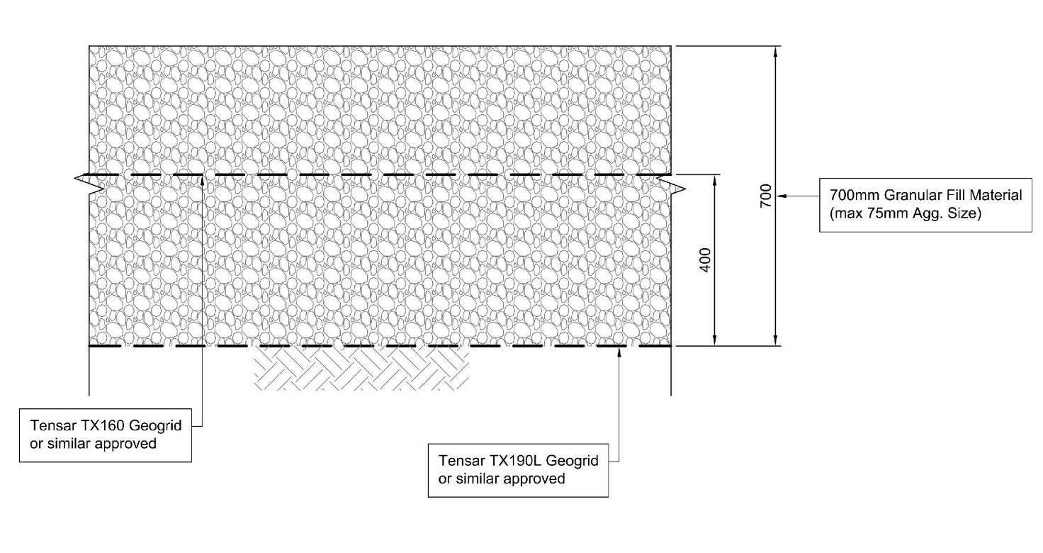
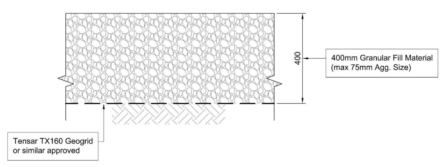
Granular road build-up (unsurfaced)
Unsurfaced granular haul roads are widely used on construction sites across the country for the movement and tracking of plant and other vehicles. They are cheap and easy to install making them very effective for use as temporary works on most projects. Their primary purposes are to protect subgrades and spread loads, preventing bearing failure of weaker soils from the often onerous loading induced by construction plant. As they are granular, they are free draining. This reduces complications that may arise on site from pooling water leading to saturated and boggy ground conditions.
The design of the granular unsurfaced road option has been designed in accordance with recommendations listed within the following design standards:
- DMRB IAN 73/06 Design Guidance for Road Pavement Foundations (DRAFT HD25) [2] (now CD 225 – Design for new pavement foundations) [3]
- New Roads and Street Works Act 1991 (NRSWA) [10]
- TRRL LR1132 [7]
Geogrid reinforcement has been incorporated in the design for the granular road options and the Tensar Pave software has been used to determine construction thicknesses and geogrid type required. Calculated unreinforced construction thicknesses from Tensar Pave have been cross referenced against the above design standards.
The key properties of this form of construction is the low costs and speed at which it can be installed. These are important features that lead it to be an extremely popular choice for temporary access roads, although in longer projects the high maintenance requirements can potentially outweigh the benefits. Please see table 3 in cost estimate breakdown and properties comparison section for further details.
Lime stabilised build-up with a granular wearing surface
This form of construction is identical to the previously discussed granular road build up, but with an additional first step of subgrade ground improvement. This is only applicable for sections of road with poor ground conditions (a subgrade with a CBR of 2.5% will not gain much benefit from lime stabilisation). Lime stabilisation of a subgrade involves the addition of a binder such as quicklime to the ground, reducing moisture content significantly and creating a more stable base [11].
The design of the lime stabilised granular unsurfaced road option has been designed in accordance with recommendations listed within the following design standards:
- DMRB IAN 73/06 Design Guidance for Road Pavement Foundations (DRAFT HD25) [2] (now CD 225 – Design for new pavement foundations) [3]
- Britpave Guidance BP62 [12]
- HA 74/07 Treatment of Fill and Capping Materials Using Either Lime or Cement or Both [13]
- New Roads and Street Works Act 1991 (NRSWA) [10]
Geogrid reinforcement has been incorporated in the design for the granular road options and the Tensar Pave software has been used to determine construction thicknesses and geogrid type required using a CBR value, upon the stabilised layer, of 2.5% (as advised within IAN 73/06 5.19) [2]. Calculated unreinforced construction thicknesses from Tensar Pave have been cross referenced against the above design standards.
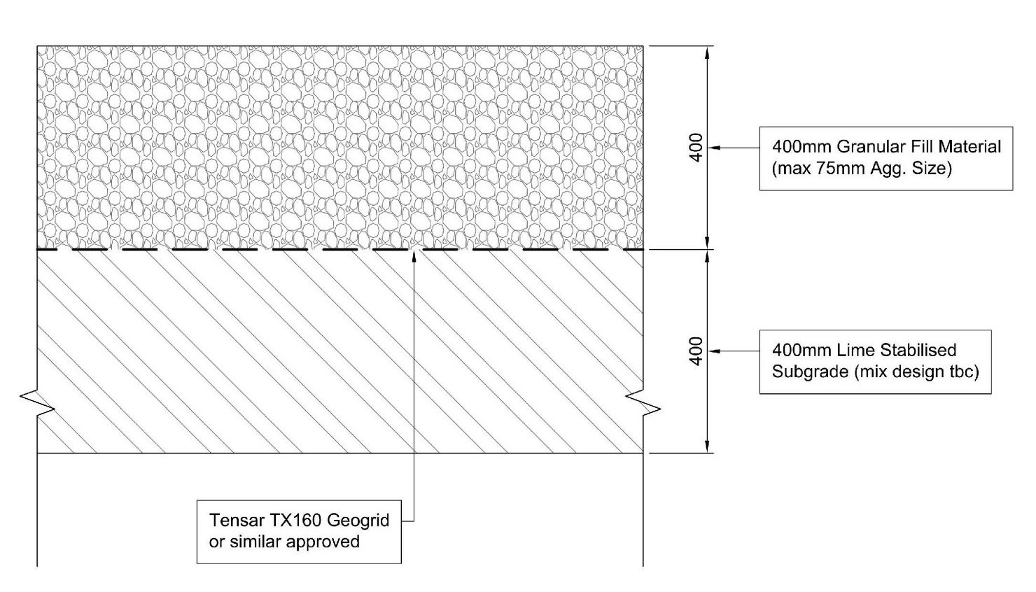
The finished surface shares the properties of the previously discussed unsurfaced granular road build up. The soil stabilisation affects the subbase and provides improved static load resistance, more resilient behaviour under dynamic loads, reduced permeability and improved free-thaw resistance. The in-situ treatment of soil can be more cost-effective than traditional ‘dig and dump’ which incur transport, importation and disposal costs. However, this traditional ‘lime stabilisation’ is now seldom used as it is less easy to control in the field compared to lime and cement. See table 3 in cost estimate breakdown and properties comparison section for further details.
Granular road build-up with surface dressing
This form of construction is identical to the previously discussed granular road build up, but with an additional bitumen surface dressing on top of the granular material. Working collaboratively with Ayton Products (a division of Kier Highways) the application of a surface dressing can be developed to suit the requirements of the HS2 C2 and C3 access road.
An outline application process:
- Application of prime coat on a granular surface
- Double surface dressing (size of aggregate and rate to be determined, depending on traffic volume, speed etc.) including polymer modified cationic emulsion (developed in house by Ayton Products)
- Reference for design to TRL611
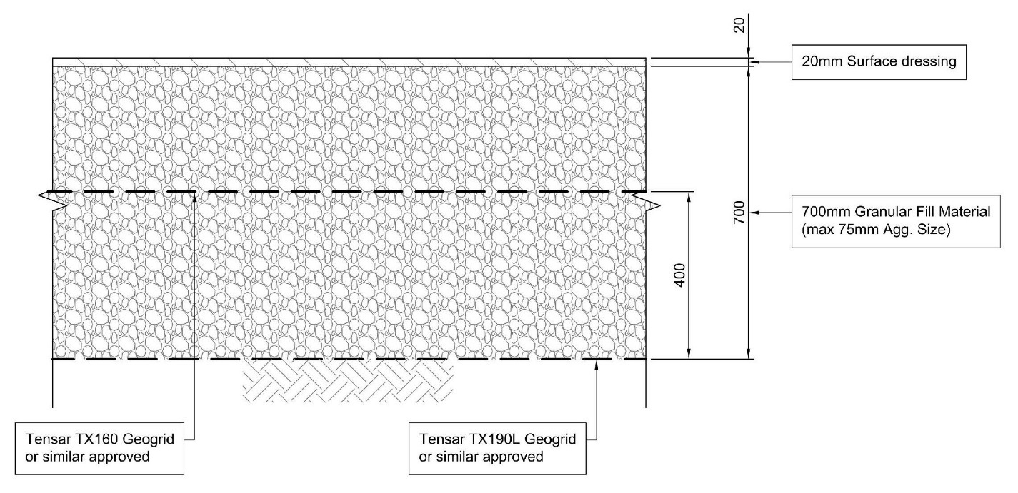
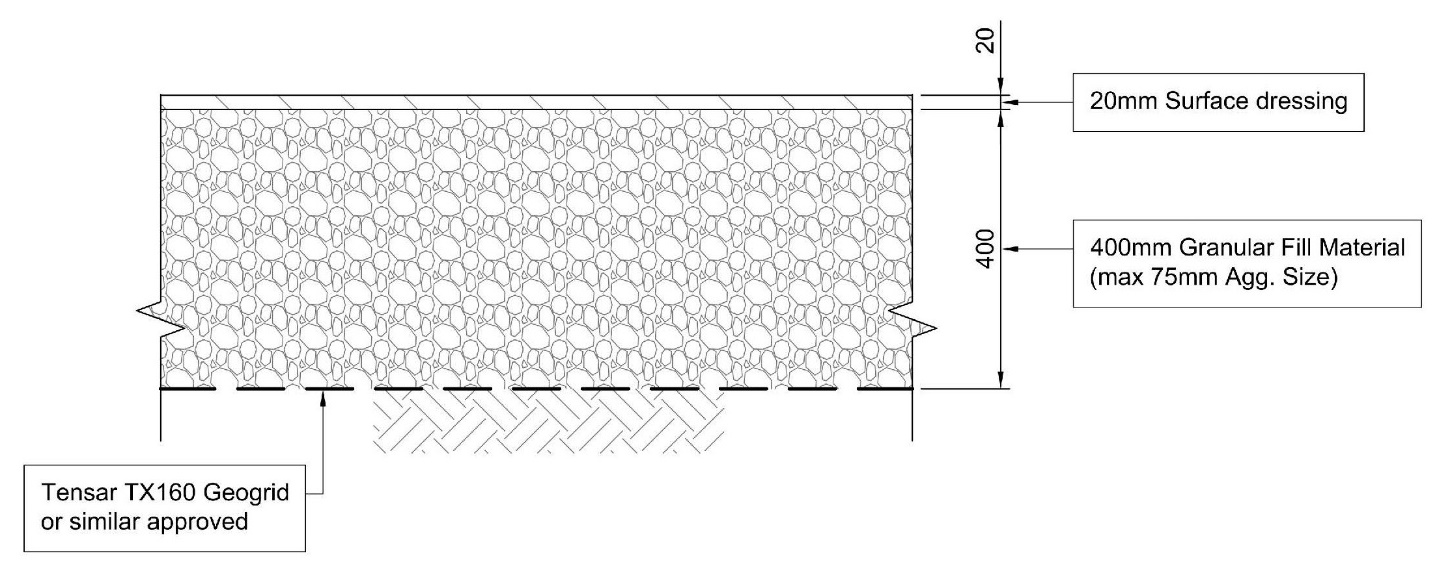
This is a less traditional form of road construction that hopes to combine the low costs and simplicity of installation of the unsurfaced options with the low maintenance requirements and improved safety of the dressed options more typically seen in permanent works. Due to the scale HS2, realising the benefits of both could have significant impacts on costs and safety implications. Please see table 3 in cost estimate breakdown and properties comparison section for further details.
Cost estimate breakdown and properties comparison
Material costs presented in the tables on the following pages have been provided by the HS2 project team. A preliminary cost for surface dressing has been provided by Ayton products.
| Road Construction Type | Asphalt Pavement | RCC Pavement | Granular Unsurfaced Pavement | Soil Stabilised Granular Unsurfaced Pavement | Granular Surfaced Dressed Pavement |
|---|---|---|---|---|---|
|
Soil stabilisation depth (mm) and cost / m3 |
N/A |
N/A |
N/A |
400 mm (TBC following test results) £10/m3 |
N/A |
|
Granular foundation depth (mm) and cost / m3 |
450 mm £96.26/m3 |
540 mm £96.26/m3 |
700 mm £96.26/m3 |
400 mm £96.26/m3 |
700 mm £96.26/m3 |
|
Surfacing depth (mm) and cost / m2 |
140 mm £49/m2 |
175 mm £25.40/m2 |
N/A |
N/A |
20 mm £6/m2 (Approx.) |
|
Maintenance required (over 5 years) |
N |
N |
Y |
Y |
N |
|
Total Cost for Foundation 100 km x 8 m Road |
£34.7m |
£41.6m |
£54m + Maintenance costs over 5 years |
£32m £30.8m + Maintenance costs over 5 years |
£53.9m |
|
Total Cost for Surfacing 100 km x 8 m Road |
£39.2 |
£20.3m |
N/A |
N/A |
£4.8m |
|
Cost Ranking |
5 |
4 |
2 |
3 |
1 |
| Road Construction Type | Asphalt Pavement | RCC Pavement | Granular Unsurfaced Pavement | Soil Stabilised Granular Unsurfaced Pavement | Granular Surfaced Dressed Pavement |
|---|---|---|---|---|---|
|
Soil stabilisation depth (mm) and cost / m3 |
N/A |
N/A |
N/A |
N/A |
N/A |
|
Granular foundation depth (mm) and cost / m3 |
300 mm £96.26/m3 |
345 mm £96.26/m3 |
400 mm £96.26/m3 |
N/A |
400 mm £96.26/m3 |
|
Surfacing depth (mm) and cost / m2 |
140 mm £49/m2 |
175 mm £25.40/m2- |
N/A |
N/A |
20 mm £6/m2 (Approx.) |
|
Maintenance required (over 5 Years) |
N |
N |
Y |
N/A |
N |
|
Total Cost for Foundation 100 km x 8 m Road |
£23.1m |
£26.6m |
£30.8m + Maintenance costs over 5 years |
N/A |
£30.8m |
|
Total Cost for Surfacing 100 km x 8 m Road |
£39.2m |
£20.3m |
N/A |
N/A |
£4.8m |
|
Cost Ranking |
4 |
3 |
2 |
1 |
Results / discussion
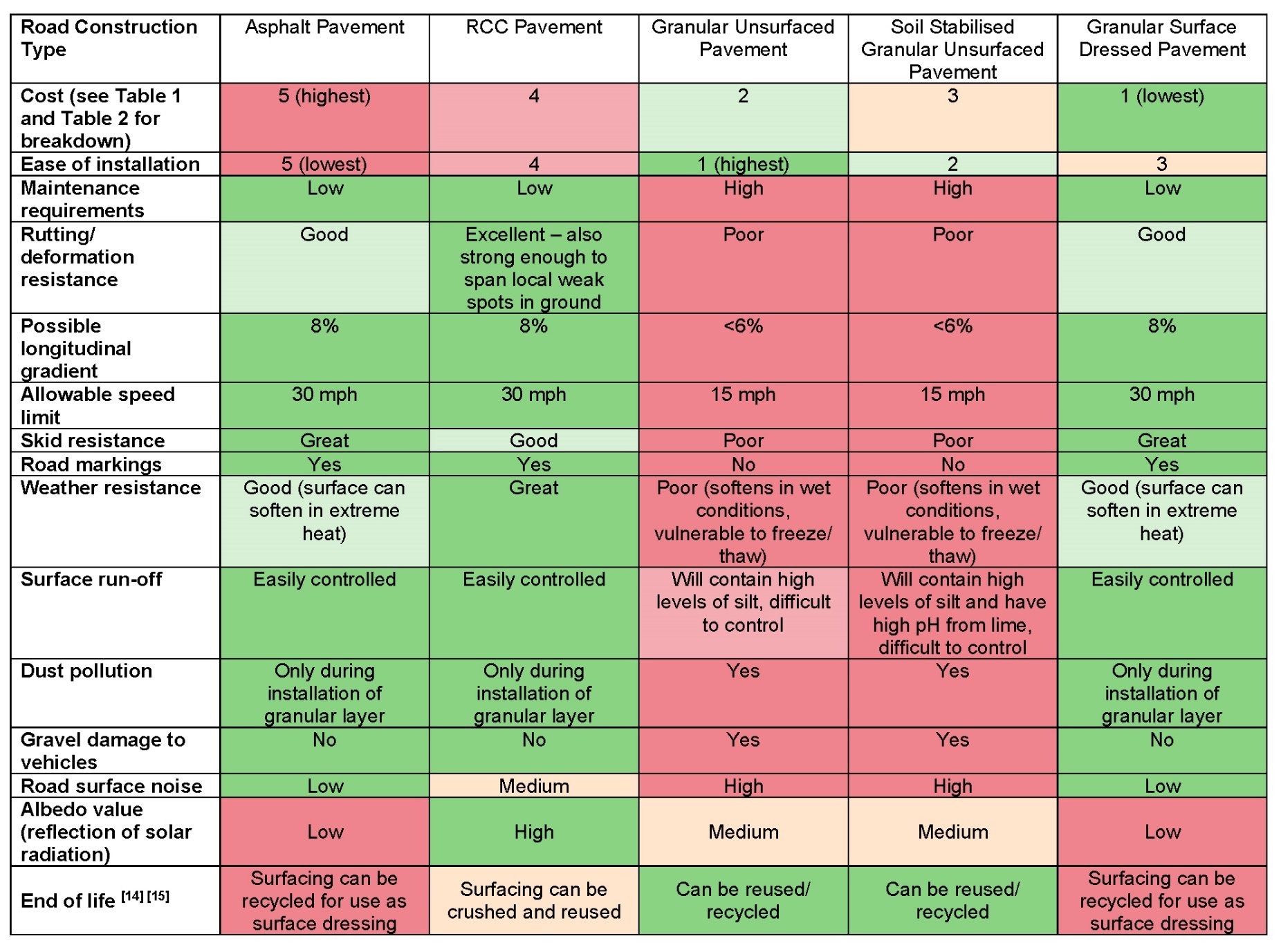
After analysing the costs, benefits and limitations of each form of pavement construction, it is now possible to compare the different forms of construction against one another. See Table 3 above for a brief overview of each form of construction against a variety of criteria.
It can be shown that there is seemingly no benefit to using an unsurfaced granular access road over a dressed pavement. Any initial benefits from using a purely granular construction (ease of installation, low initial cost) are outweighed by the additional costs and complications required by their intensive maintenance schedule when used on a project of this size. The granular constructions also have issues with safety and environmental impact when considering water run-off, poor skid resistance and risks associated with the kicking up of dust and gravel.
Between the three surfaced options, there are only very small differences in restrictions and qualitative properties. All three are capable of the same speed limits and longitudinal gradients, and all provide similarly effective control of surface run-off, weather resistance and skid resistance. They all have similarly low maintenance requirements when implemented on an access road with this level of traffic and design life. Any small differences such as road surface noise and albedo value may be important when used in a permanent works design in a populated area, but for use in an application such as this are not critical. The simple surface dressed granular construction has the advantage of being significantly cheaper and easier to install than the heavier duty asphalt and RCC constructed pavements.
Conclusion
Upon review of the road options, it was recommended that a surfaced dressed granular road is considered for the site access roads.
This recommendation was based on the reduced costs and programme savings that this road type provides over the other options. This option mitigates and removes disadvantages previously identified with a granular only surface and simplifies the construction method by using one foundation type. The surface dressing would reduce the requirement for maintenance and will allow road markings to be applied.
The findings of this investigation could prove useful in future projects where long stretches of temporary access road are required with a high volume of predicted axle passes. These are typically most common in transport projects, particularly major infrastructure projects. If the solution was implemented and proved successful, there could be immediate scope for further application on Phase 2a and 2b of HS2.
A potential area for further research would be the possible implementation of the surface dressed options as accompanying permanent features to the primary works, for example by adapting the temporary roads into permanent cycle ways after project completion. This could result in further environmental and social benefits to future schemes at relatively low cost.
References
Otto, A. and Tumwesige, R. A Methodology of Pavement Design for Upgrading Gravel Roads. Institution of Civil Engineers, 2017.
Highways Agency, IAN 73/06 Design Guidance for Road Pavement Foundations (DRAFT HD25), 2009.
Highways England, CD 225 Design for New Pavement Foundations, 2020.
Highways Agency, HD26/06 Pavement Design, 2006.
Highways England, CD 226 Design for New Pavement Construction, 2020.
Transport Research Laboratory, Rode Note 29 A Guide to the Structural Design of Pavements for New Roads, 1970.
Powell, W.D., Potter, J.F., Mayhew, H.C., and Nunn, M.E. Laboratory Report 1132 The Structural Design of Bituminous Roads, Transport Research Laboratory, 1984.
Britpave, BP/64 A Guide to Concrete Road Pavements, 2018.
Britpave, BP/55 Guide to Roller Compacted Concrete Pavements, 2013.
Department for Transport, New Roads and Street Works Act 1991, 2012.
Chaddock, B.C.J. and Atkinson, V.M. Stabilised Sub-bases in Road Foundations: Structural Assessment and Benefits TRL Report 248. Transport Research Laboratory, 1997
Britpave, BP/62 Soil Improvement and Soil Stabilisation Definitive Industry Guidance, 2017.
Highways Agency, DMRB Volume 4 Section 1 Part 6 HA 74/07 Treatment of Fill and Capping Materials Using Either Lime or Cement or Both, 2007.
Merrill, D., Nunn, M. and Carswell, I. A Guide to the Use and Specification of Cold Recycled Materials for the Maintenance of Road Pavements TRL611. Transport Research Laboratory, 2004.
Reid, J.M., Chandler, J.W.E., Schiavi, I., Hewitt, A., Griffiths, R. and Bendall, E. Sustainable Choice of Materials for Highway Works: A Guide for Local Authority Highway Engineers PPR233. Transport Research Laboratory, 2008.
Notation
- AADT – Annual Average Daily Traffic
- CBR – California Bearing Ratio
- HRA – Hot Rolled Asphalt
- msa – Million Standard Axles
- RCC – Roller Compacted Concrete
Peer review
- Nick Sartain, Head of Geotechnical EngineeringHS2 Ltd