The slowest part of HS2 – The design of HS2 automated people mover
The HS2 Automated People Mover (APM) provides the link between the new Interchange Station and existing local infrastructure of the NEC, Birmingham International Railway Station and Birmingham Airport. The system therefore provides a key piece of the connectivity of HS2 to the region.
Located on an elevated viaduct, the APM is also unique amongst the HS2 contracts in that it passes through third party operational sites that HS2 will not be the landowner post construction. The design has therefore involved significant stakeholder consultation and integration.
The design of the system, structures and stops has required intensive and complex multi-disciplinary working. The resulting design is a triumph of integration and economy with over 80 staff, representing over 30 disciplines, combining to generate a design that efficiently packages multiple elements into a unified design that truly exceeds the sum of its parts. The success of the design lies in how both engineering and architecture have been given equal prominence in the design, with neither controlling or dominating the design.
The core message is that functional and cost effective should not mean bad design is accepted in infrastructure. By adopting a simple but strong concept and applying it rigorously throughout the design, this paper shows how this can and should be achieved on infrastructure projects.
- Written by
-
Chris Jackson

- Resource type
- Resource type: Technical Paper
Introduction
The HS2 automated people mover (APM) provides the link between the Interchange Station near Solihull, the surrounding community and existing national rail and international airport infrastructure. The system is therefore crucial to the overall connectivity of HS2. The scheme design of the system has required a complex blend of architecture, structures, systems, communications, fire engineering, operations, human factors, mechanical, electrical and plumbing disciplines. These have combined to create a truly integrated design.
The APM route runs between Interchange Station and Birmingham Airport via the National Exhibition Centre (NEC) and the existing Birmingham International Railway Station (BIRS). Whilst only 2200m in length, the route spans over most land types including greenfield, the M42 motorway, NEC car parks, a lake, NEC buildings, the West Coast Mainline (WCML), local roads and the primary approach road to Birmingham Airport.
Furthermore, the route requires Stops to be built within the sites of the NEC, BIRS and Birmingham Airport whilst these remain operational throughout. This unique situation has driven the design of the system and was described by the project team as ‘building with ballet shoes on’.
System selection
The first challenge was to define what the APM system was going to be. The requirements for the system were high level, focussing on the overriding parameters of journey time, frequency and capacity to be achieved. The requirements for these three parameters are stated as part of the hybrid Bill based on passenger demand modelling carried out at that time.
From these requirements and a detailed assessment of possible systems ranging from light rail to cable cars, the system type selection was reduced to either a cable pulled or self-propelled APM system. Having reduced the possibilities to these two system types it was decided to develop the design to be compatible with both system types in order to provide flexibility for tendering and future upgrades.
The system types available on the market were modelled in detail to understand the capacities achieved and the number and length of vehicles that would be needed to meet the requirements. Whilst two vehicles acting in a simple shuttle configuration could meet the required capacity and journey time, the only way to achieve the frequency requirement was to use a minimum of four vehicles. The need for four vehicles combined with the requirements of cable pulled propulsion meant that the system needed to be a ‘pinched loop’ configuration.
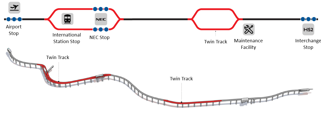
The pinched loop layout was then optimised to reduce the scale and cost of viaduct. This was achieved by only provide two tracks where required for vehicles to pass each other. The highly reliable, frequent and closed loop nature of APM systems makes this possible. The functional layout and areas of twin track are shown in Figure 1.
Design response
A complex site
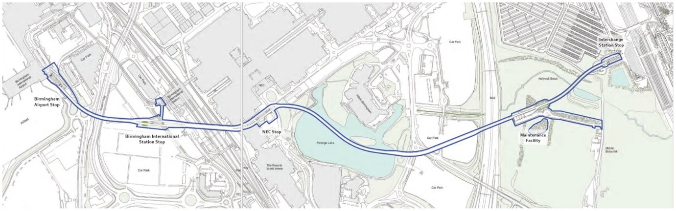
The APM passes through a both rural site and a dense area of nationally critical infrastructure. These wide-ranging areas were critical to developing the design response for the system. The overall site is shown on Figure 2.
The area between the new HS2 Interchange Station and the M42 motorway is predominately agricultural and includes the Hollywell Brook and valley, characterised by pockets of woodland, including trees and a network of hedgerows. This area, and the wider Interchange Station Site more generally, is however now undergoing change with various enabling and other HS2 works taking place.
To the west of the M42 motorway, land use is predominantly urban providing areas of key transport infrastructure, employment, recreation and commercial uses. Existing infrastructure and development along and / or adjacent to the proposed alignment of the people mover includes the M42 itself, the Hilton Birmingham Metropole and Crown Plaza hotels, the NEC complex, Resorts World, Birmingham International Rail Station, and Birmingham Airport. As the proposed alignment of the people mover passes through this area to the west of the M42, it crosses other existing highways, multiple areas of parking, Pendigo Lake (a man-made lake situated within the NEC complex), the link hall between the Pavilion and Hall 1 of the NEC, the West Coast Main Line (WCML), Bickenhill Lane, before finally crossing over internal access roads associated with Birmingham Airport.
Stop locations
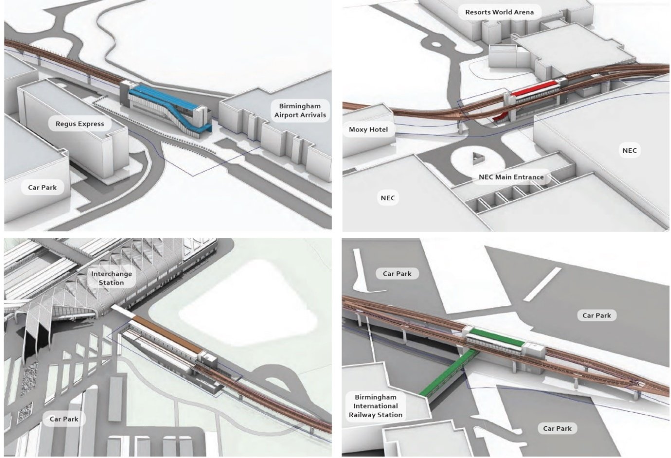
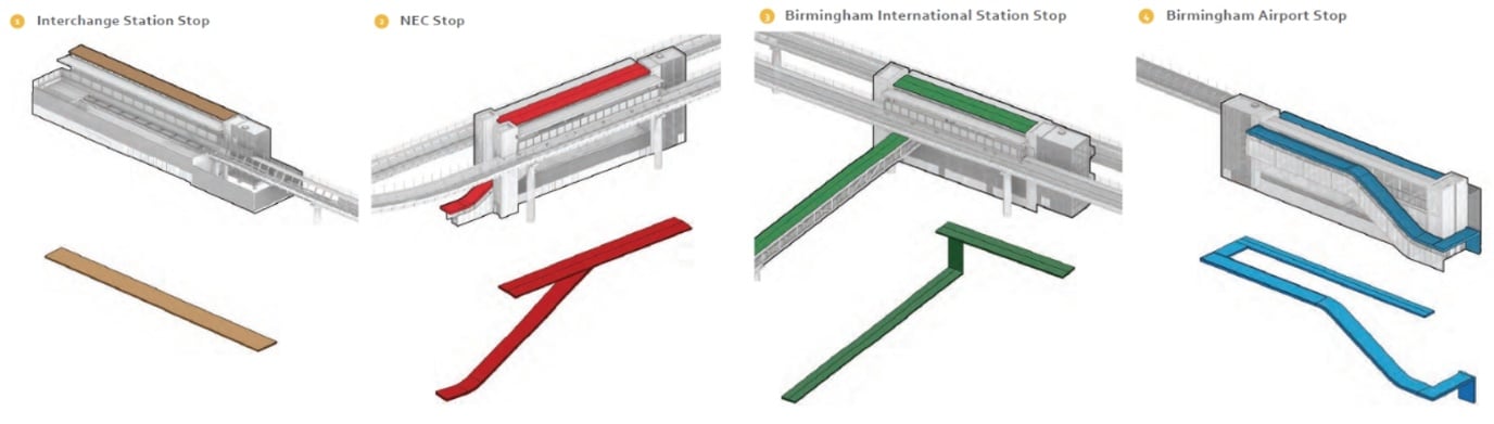
The alignment corridor for the route and the required stopping points were set during the preparation of the hybrid Bill. Having selected the system type the alignment and stop locations were refined. In total there are four stops on the route, these are each shown in their site context in Figure 3:
- The Interchange Station Stop is located immediately adjacent to the HS2 Interchange Station.
- The NEC stop is located next to the south of the main entrance to the NEC Exhibitions Halls and to the west of Pendigo Lake.
- The Birmingham International Station stop is situated to the south west of Birmingham International Railway Station in the existing long stay station car park.
- The Birmingham Airport Stop is located at the southern end of the Airport arrivals hall.
- The on-line Maintenance Facility is located adjacent to the M42.
The nature of the route with multiple existing sites and contexts, required a sensitive touch to create a design that achieved the high level of design required for such a prominent structure whilst also respecting the budget requirements of HS2 and had constructability at its heart.
Design principles
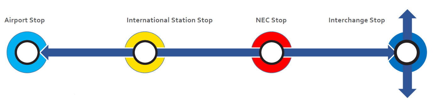
The design team response to these complex drivers was to use the APM design to project the HS2 identity and connectivity through the sites whilst also allowing the stops to respond to the sites they are located in. This concept is illustrated in Figure 4. To achieve this the viaduct is designed as a continuous ribbon like feature that takes design leads from the HS2 mainline infrastructure. The stops are designed with a common design language for the user but with the ability to respond to the surrounding environments. The design of the viaduct and stops is described in detail through the rest of this paper.
Viaduct design
Evolution of viaduct form
To achieve the desired ‘ribbon’ concept for the viaduct it was crucial to provide an efficient and slender structure that could support single and double tracks whilst maintaining a consistent appearance. The first step in the design of the viaduct was to understand the loading it would need to resist. There are no standardised loads for APM systems, therefore a literature review of past APM projects and supplier requirements was carried out to generate a bespoke load basis for the project.
The design team also sought to integrate the track system into the structure to provide a tightly packaged and integrated viaduct, far more so than is the norm for railway structures. This led to the evolution of the viaduct as shown in the images in Figure 5 and described further below.
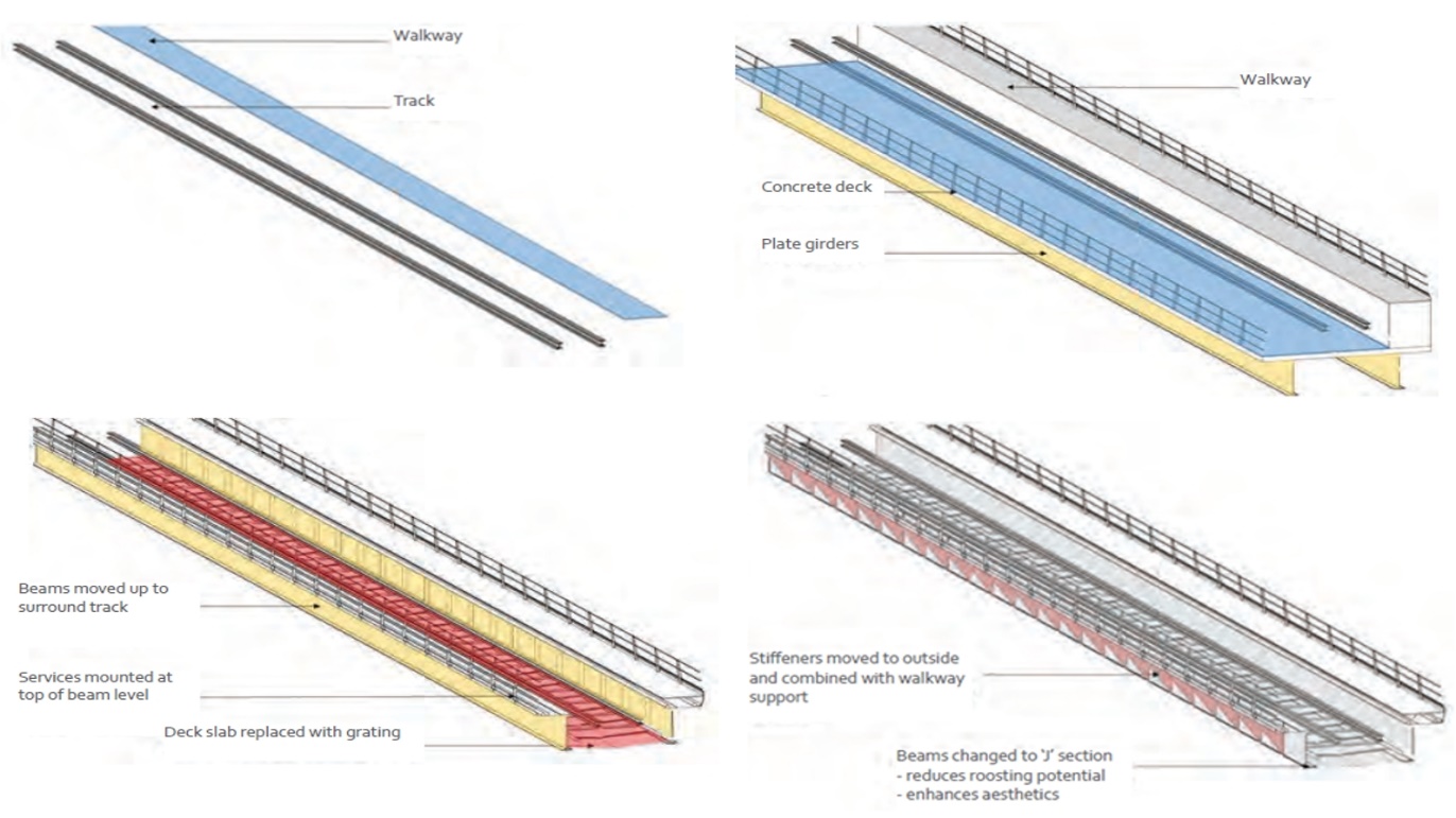
As an unmanned system, an escape walkway is required throughout to allow self evacuation. The location of this walkway relative to the track is geometrically fixed by its functional requirement.
For a twin track APMs structure the walkway tends to be located centrally and is therefore not dominant from the side of the structure, meaning that a standard beam and slab deck provides an efficient support structure. With the change to large areas of single track, this walkway on top of the deck span with beams below creates a visually, very heavy structure that was not appropriate in the prominent location of the APM.
To reduce the visual depth the structure was switched to a half through type structure by placing the beams alongside the track. The result is that the structural depth and walkway depth are overlapped and therefore the overall impression is a slenderer structure.
Market engagement with APM suppliers determined that the systems could be supported directly from the steelwork and therefore a solid concrete deck slab was not necessary. The slab was replaced with a simple grating for access.
The grated deck eliminates over 10,000m3 of concrete from the design, giving large carbon savings, reduced construction periods, reduced work at height as well as driving significant cost savings both directly in the deck and indirectly through reduced foundation demands.
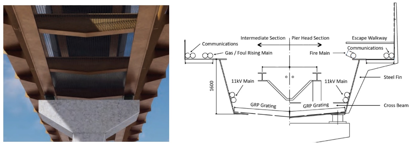
The final stages of the viaduct design included shaping the fins that act as web stiffeners and walkway support and angling of the beams to soften the visual of the structure. Careful integration of the system utilities was carried out to ensure space in the structure for the various power, communications and firefighting mains required. Services integration in the viaduct was crucial as, except for potable water and drainage connections, the APM system is entirely serviced along the viaduct from Interchange Station.
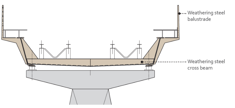
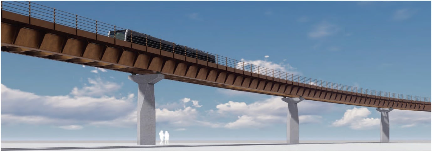
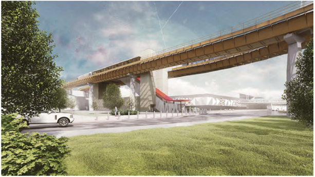
The final consideration of the deck form was the need to accommodate the twin track sections of the route. The form selected allowed the cross beam to be lengthened, giving a simple solution to this scenario. This approach maintains the structural elevation throughout the whole route. The final deck cross sections are shown in Figures 6 and 7 with a general visualisation in Figure 8.
Deck structural system
The cross beams required to support the APM system combine with uprights to form a structural U frame to prevent the top flange from buckling. This provides the rigidity the system requires and controls torsion effects on the highly curved alignment. The deck is generally continuous and supported on bearings at the columns. Movement joints are provided at appropriate points along the viaduct, coincident with track joints for the APM system and on straight and constant gradient track.
The distance from the top of the cross beam to the walkway is set by the system requirements. Combined with utility space requirements this gives a beam depth of 1.6m. This depth makes spans in the order of 40m efficient. To give a pleasing aesthetic a regular rhythm of columns is crucial. Following study of the site and experimenting with grids ranging from 25m to 50m, it was concluded that a 40m column grid integrated best into the site, minimising infrastructure that needed diversion, whilst not extending spans longer than necessary.
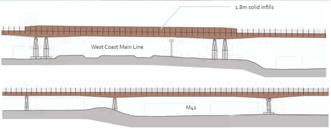
In two locations along the route a longer span of 70m was required to span over the West Coast Mainline and M42 Motorway. This was not feasible with the beam depth selected. To solve this issue a haunched beam was introduced along with a 2m deep section midspan. This approach also provided sufficient space to include drainage carrier pipes over the WCML, where the presence of Overhead Line Equipment (OLE) on the railway dictated a need for a solid deck plate. These spans are shown in Figure 9.
Evolution of viaduct form
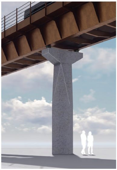
For the columns, the design decision was to consciously keep the columns simple so as not to detract from the deck ribbon concept. Repetition of design was key to ensure cost effective design and construction at over 50 locations.
A number of forms were studied in detail. The concept of a shaped top that could be standardised for all columns with a straight shaft that could be adjusted in height to suit the topography was adopted. Adjusting the column cross section to respond to different heights was studied but having reviewed several approaches to this it was concluded that a constant column size was the more appropriate visual and construction solution. This column is shown in Figure 10.
Materiality
Material selection for such a prominent structure required careful consideration. Many materials were considered with the decision taken to adopt a weathering steel structure. This will darken over time giving an effect that suits both urban and rural environments with a finish that time enhances rather than degrades. Furthermore, the weathering steel eliminated the need for future painting that would have been highly disruptive to the sites the route passes through and could result in significant environmental issues to the waterbodies crossed from sand blasting activities.
The columns are in reinforced concrete. Great care has been taken to ensure the weathering steel deck will not drip continuously onto the piers creating staining. These measures include solid bays in the deck grating at piers and drip stop details.
Analysis and optimisation
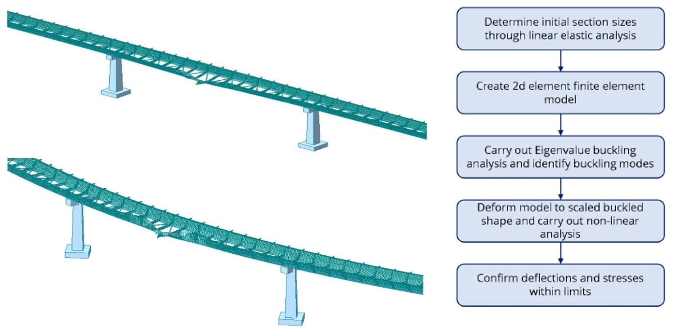
The APM viaduct is an unusual structural form for the length of the structure. Great care has been taken in the scheme design to analyse and fully understand the behaviour of the structure. The steel U frame structure is governed by buckling throughout meaning the stiffness of the U frames is critical, however with over 1000 of these frames along the route it was also important to optimise the amount of material in these frames. This has been achieved using automated model generation tools to carry out buckling analyses and optimise the structure. This analysis is more complex than normally carried out for scheme design, but by optimising the steelwork design early, the benefits of this can be better integrated into the scheme and construction planning for the scheme. Example analysis models are shown in Figure 11.
Modelling and design integration
The use of Building Information Modelling (BIM) has been implemented throughout the design of the structure. The viaduct has been modelled parametrically in Revit, using automation in Dynamo to efficiently remodel the structure as the design developed and the analysis refined. This approach also benefits the design for construction as it drives the use of standardised components throughout the design.
Design for construction
Throughout the development of the viaduct, construction has played a crucial consideration. The nature of the site means that access will always be challenging with stakeholders wanting the minimum disruption feasible whilst a major viaduct structure is built through their sites.
The steel design of the viaduct has been conceived as highly modular with repetitive details throughout. The use of steel with no concrete allows the deck sections to be assembled in the site compound prior to lifting into place. The sections of viaduct are anticipated to arrive on site in smaller elements, sized for transportation and then be assembled into deck modules at ground level.
Construction proposals have been developed sitewide to ensure that all sections of the viaduct can be built efficiently, with compounds and delivery routes identified. Steelwork detail concepts were also developed with steelwork fabricators to ensure the concepts had buildability at their core.
Design of stops
Stop concept
The APM stops sit within a range of environments. The design of the APM is intended to present a linear piece of infrastructure that identifies as HS2, whilst allowing the stops to respond to the local context of each stop. The Airport, NEC, BIRS and Interchange Station all have differing degrees of openness and scale of adjacent buildings.
In designing the stops stakeholder consultation has been crucial to achieve visual, operational and security integration into the operations plans of those sites. In each case the immediate public realm and vehicular access is adapted to suit the existing operational and security requirements of their respective locations.
To achieve integration with the sites in which the stops are located, the external materials, colours and textures are selected to be appropriate to the location. Entry and exit points for both public and servicing of the stops are selected to suit the site layouts and fit into the wider pedestrian flows of the site.
User centric design
The overarching aim for the people mover system is for the stops to be legible and familiar for every user and at the same time be customised to its location. Each stop is composed of a family of standardised elements that are applied consistently so that layout is instantly recognisable. This allow users to easily navigate the stop.
The starting point for this concept is to delineate the circulation as a clearly articulated element that is customised based on location and that helps to guide passengers from platform to exit. This element is expressed as a ribbon, echoing the viaduct ribbon. It flows through the stop as a coloured overhead plane threading its way through from entry to platform level defining the passenger circulation. At platform level the ribbon becomes part of the canopy. The ribbon also acts as a beacon helping to direct passengers seamlessly towards the stop entrance. The colour of the ribbon is customised at each stop and broadly is inspired by its location with but variegated around a common hue, reflecting the principles of nature. The ribbon for each stop is shown in Figure 13.
Operation functional design
The APM stops are, by their nature, small and compact structures. The sizing is therefore dominated by the functional needs of the plant and systems required to operate the system. The stop footprints have been minimised as far as possible by understanding in detail the required equipment, interdependencies and servicing. The limited space and desire to reduce vertical elements in the design have made vertical transportation and MEP routing key considerations in the design.
Stop types
The functional needs of the APM system results in the stop designs grouping into two main categories. At each end of the route the terminus stops house large amounts of motor rooms and drive equipment with a single sided platform for the APM pinched loop configuration. To meet these needs these stops are formed as independent building structures that fill the space between ground level and the track level.
The intermediate stops have a significantly reduced equipment need and feature an island platform layout. The platform is therefore supported off the viaduct with plant in single story structures at ground level. This creates a gap between plant rooms and viaduct, reducing the visual mass of the structure.
To tie these two stop layouts into a unified system, a set of common components are used throughout the public areas of the stops. The common elements include: the ribbon feature; platform design; edge doors; canopies; escape cores; lifts; and escalators.
At the heart of each of these elements is simplicity. Each of the elements in itself is simply designed and paired back to its base purpose. It is the integration of the elements into a compact package that is at the heart of the stop design.
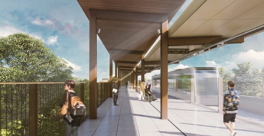
Platforms
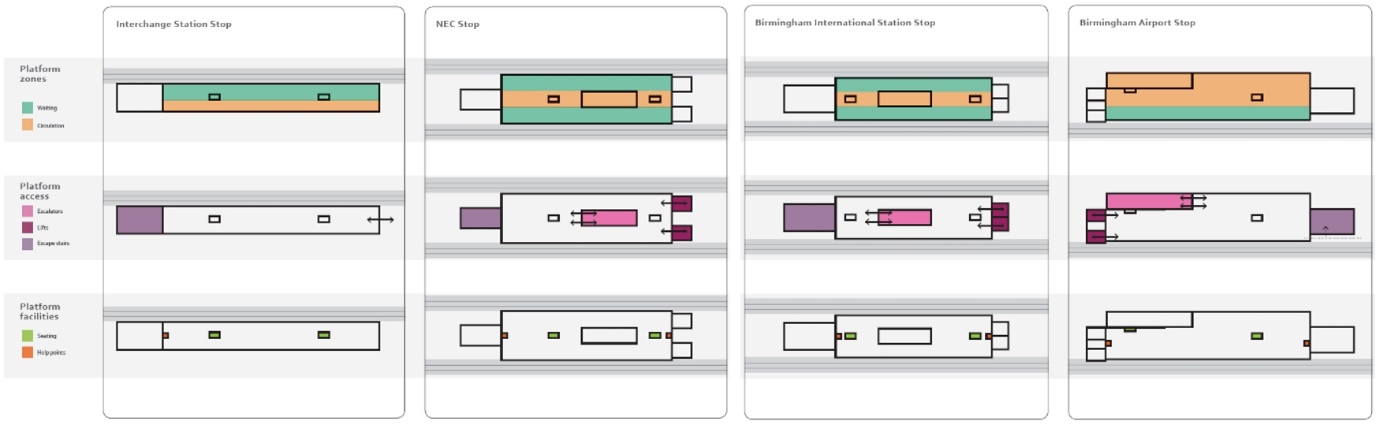
The design for the platforms creates a durable and modern space, which clearly allows the customer to board and alight the trains quickly and navigate the space efficiently. Clear, uninterrupted platform zones are provided along the edge zones of the platforms, with a central zone for circulation and structure. The central zone provides necessary runoff distances for all vertical circulation.
The platforms vary from 36 to 40 m long. Widths have been determined by vertical circulation requirements and are designed to accommodate a bank of two escalators, leaving 3m clear width on either side. Platforms have been laid out in order to encourage separation of uses between waiting and queuing, circulation, and the platform edge safety zone (Figure 14). Platform edge doors are located alongside the platforms providing security and safety for passengers when on the platform. Combined with the canopy, the platform edge doors provide a good degree of weather protection for passengers.
Platform canopies
The platforms are fully covered. The canopies are split to reflect both the concept of the ribbon and the function underneath.
The canopy over the circulation zone is raised by 600mm with the lower part of the canopy over the waiting zone next to the tracks. The gap between the canopies allows natural light into the centre of the platform. The overhangs have been carefully detailed to prevent rain ingress at the level change.
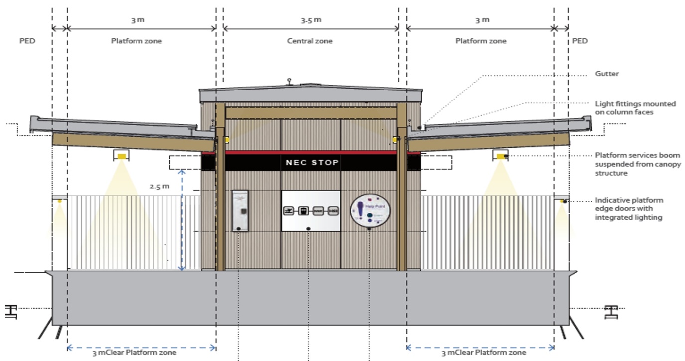
The canopies sit on a simple primary set of steel portals formed from rectangular sections. Joints are welded and ground down flush forming a seamless continuous frame. The frames are set at approximately 9 metre centres. The canopies are externally finished with aluminium standing seam with gutters incorporated into the lower canopies and are fully lined on the underside with aluminium soffits panels. The canopy section is shown in Figure 15.
Services in canopy
Services are integrated into the service booms which run the length of the platforms. These contain all the services (lighting, speakers and CCTV cameras) required to provide a safe and efficient journey for passengers.
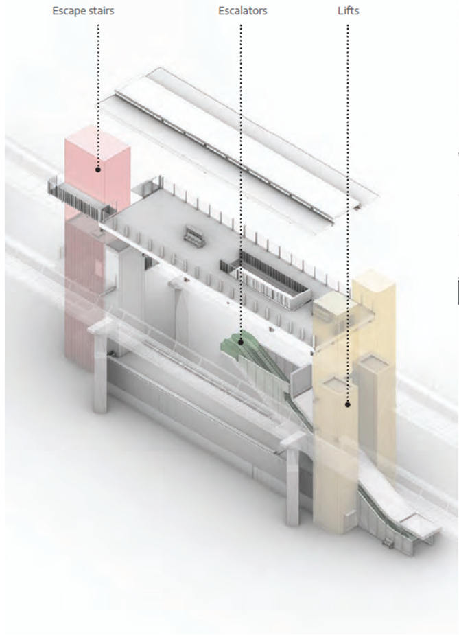
Stop vertical transportation
For the three stops requiring vertical transportation, this is provided with a pair of lifts at one end of the platform and a pair of escalators descending from the other end (Figure 16). At the Airport and NEC stops the escalators pass the lift shafts, arriving at the station entrance point at the same place. For the BIRS stop, a link bridge from a mezzanine level within the stop provides the access to the existing station. This means the level difference is less than at the other stops. This allows the lifts and escalators to arrive at the mezzanine on opposite sides of the same landing, providing a combined circulation space.
At the Interchange Station stop the platform is at the same level as the station concourse and therefore transit from the APM to the station is at grade with a simple covered walkway provided.
Stop integration to sites
Interchange station stop
The Interchange stop platform leads directly on to the station’s West Plaza, which connects the people mover platform with the Station concourse level. The Interchange Stop is a single sided platform (Figure 17). The viaduct arrives at the side of the public plaza, which creates an animated urban environment that reflects the multimodal aspect of the scheme.
The platform canopy adopts a single sided version of the standard design by being divided into two parts, with one part raised. The risers are located at the end of the platform and allow for services distribution from the lower level plant rooms directly into the services boom at the platform canopy level.
The plant rooms and motor rooms are on the lower level. They are located immediately below the platforms with vehicular access provided by the station’s service road at a lower level. An outside plant area occupies the space below the viaduct and is screened off from view with louvres. The platform paving matches the paving of the station plaza to create a coherent public realm.
NEC Stop
NEC is a through stop with a central platform serving tracks to either side. The standard three section canopy design provides shelter to the platform.
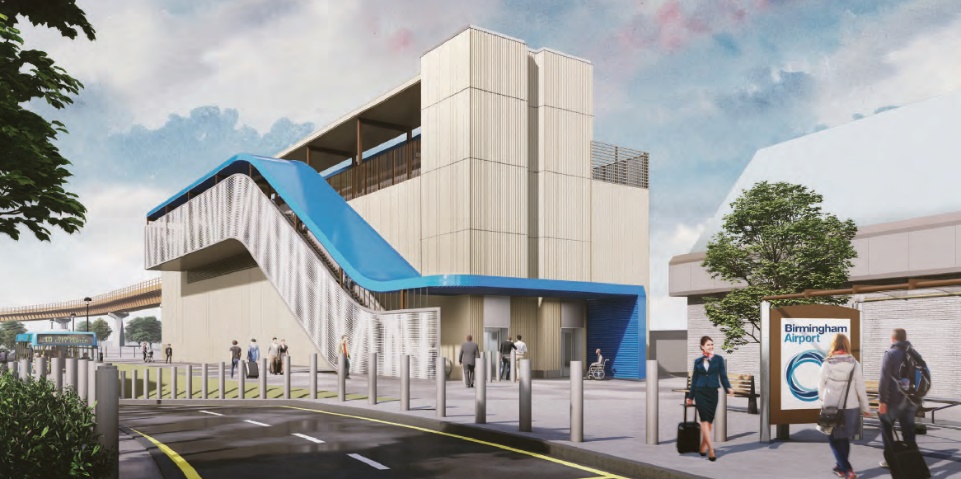
The entrance to the NEC Stop faces onto the Pendigo Way, which is the main access road leading to the NEC Plaza entrance. Twin escalators lead directly from ground level to the platform level. The stop lifts sit either side of the escalators (Figure 18).
The escape stair and services riser are located at the western end of the platform. The plant rooms are located on the ground floor with access from the perimeter service road.
The design and the location of the NEC stop has been developed with due regard to the aspirations of the NEC, which considers the Moxy Hotel, other future new developments around Pendigo Lake and the proposed refurbished entrance to the NEC building which is located just to the north of the people mover entrance.
At the stop frontage, the existing paving will be lifted and re-laid in order to tie into the finishes of the adjoining footways and maintain the appearance of Pendigo Way. The kerb line and dropped kerb are realigned at the head of the service road to the north. Seating will be provided either side of the escalator housing, in front of the lifts. Bollards will be placed along the front of the entrance to the station and will form a continuous line with NEC’s security line.
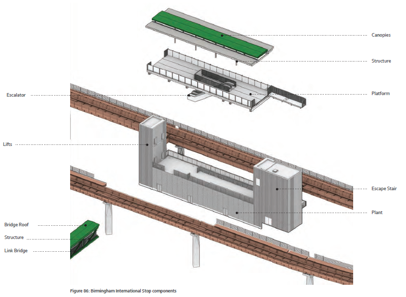
BIRS stop
BIRS is a through stop with a central platform serving tracks to either side, similar to the NEC stop, the key components are shown in figure 19. The stop is located between the two levels of the car park adjacent to BIRS. Passenger access is from the pedestrian link bridge linking the people mover International Station Stop with the railway station.
The link bridge is an elevated structure with balustrades on both sides. It connects the main concourse of the Station with the mezzanine floor of the HS2 people mover Birmingham International Station Stop. The ribbon feature continues from the platform canopy, down the escalators and along the link bridge, connecting the station to the existing railway station.
In a similar way to the NEC Stop, the escalators connecting the mezzanine to the platform level are located centrally on the platform with lifts at the opposite ends of the platform. The lifts provide emergency access to the ground floor to allow evacuation of PRMs in emergency.
Plant rooms are located between the lift cores and the riser like other stops, with the topography of the site meaning these are recessing into an existing slope, reducing the visual scale. The external and internal plant rooms are located next to one another with a common cladding to mask the different scenarios. Access to the plant rooms is from both sides of the building.
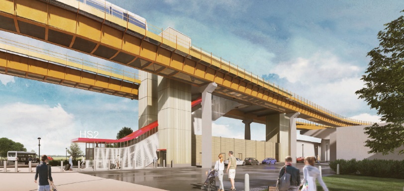
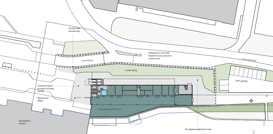
Birmingham Airport Stop
Birmingham Airport Stop is a terminus stop, similar to Interchange Station. The viaduct comes in on the side facing the airfield. The main entrance sits adjacent to the Arrivals entrance of the terminal building. The greater height of the alignment, required to cross existing roads nearby, combined with the limited space available on the site means that plant rooms are provided on the ground floor with the motor rooms required at the terminus provided on the first floor and the platform on the second floor (Figure 20).
The platform is accessed via the escalator located along the stop’s facade or the lifts at the northern end, adjacent to the airport. The canopy is again the standard three-part design. The section facing the Trident Road is extended down to form the roof of the escalator enclosure and entrance canopy, providing the ribbon motif and clear visual wayfinding.
External plant is located in a segregated service area to the rear of the structure, between the ground floor plant rooms and the existing retaining wall to the airport’s loading dock.
The passenger lifts are located at the northern end of the platform linking directly with the escalator entrance at ground level. The escape stair is located at the southern end of the platform. The risers are located at both ends of the platform, forming part of the lift enclosure at one end and of the emergency exit stair enclosure at the other end.
Externally, the stop location has required the realignment of sections of airport access roads. Design has also had to carefully consider the security provisions around this stop as it is located within Birmingham Airport’s secure perimeter (Figure 21).
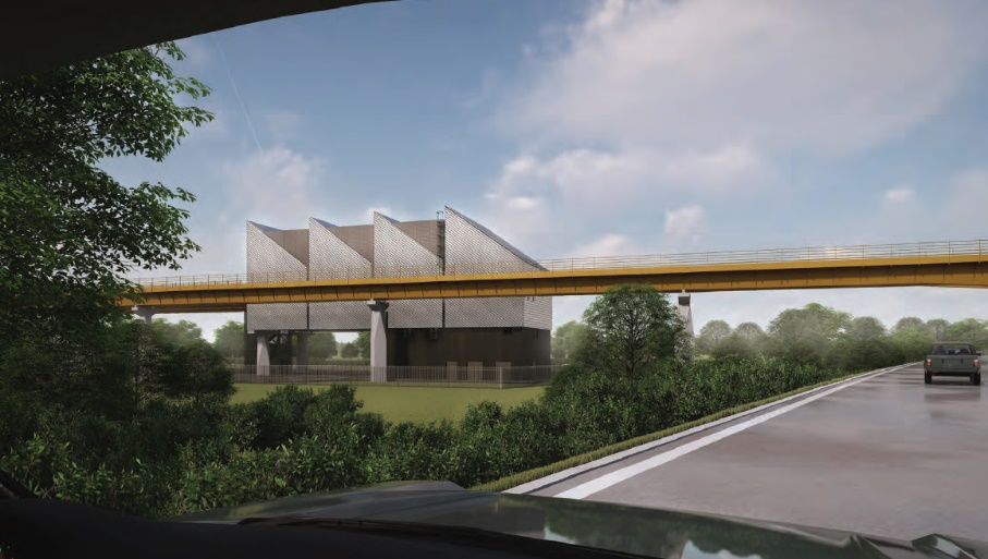
MAINTENANCE FACILITY
The Maintenance Facility is located along the viaduct to the west of Interchange Station, next to the M42. The access track for people mover vehicles to enter the Maintenance Facility is located at the eastern end of the building.
The Maintenance facility is primarily a functional building used for the maintenance of the people mover vehicles. The building consists of three main volumes – the maintenance bay, plant and the enclosed escape stair. The sizes and requirements for these have been determined based on the operational needs of the system.
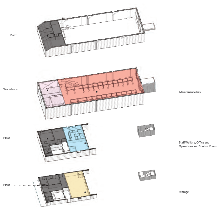
Architecturally, the concept is for the form to follow the function, with each functional element given an architectural treatment. The main volume of the maintenance bay is given an iconic saw tooth profile which is visually reinforced by breaking the length of the facade into distinct bays (Figure 22). These are further articulated by the use of standing seam cladding set at an angle to compliment the dynamic saw tooth form of the main volume of the facility.
The Maintenance Facility allows for both light and heavy maintenance and exterior washing. It is arranged over four floors as follows: Storage and plant (ground floor), plant and welfare facilities (first floor), workshop and maintenance Bay (second floor), plant and machine room (third floor). These are shown on Figure 23.
Conclusion
The APM is an unusual part of the HS2 infrastructure. This has provided the design team with many challenges to solve, often requiring consideration of the core requirements and concepts to establish the design basis for an element.
The design team adopted a simple but strong design concept and applied it rigorously throughout the design. This, combined with collaborative working, has allowed a functional piece of design to achieve the aspirations of the HS2 Design Vision whilst ensuring the benefits of HS2 connectivity are realised in the area around Interchange Station.
The design has focussed on understanding and challenging the needs of the system and its users and creating a design response that provides these needs. Throughout the design process waste has been challenged and the need for every element questioned and justified.
This will provide a legacy for HS2 and the design team hope act as a reminder that functional infrastructure can also be well designed and contribute to its surrounding environment whilst also being economic to construct. The core message is that functional and cost effective should not mean bad design is accepted in infrastructure.
Peer review
- Hala Lloyd, Lead Architect(Curzon)HS2 Ltd
- Jiten Davdra, Head of engineering and Environment (Stations)HS2 Ltd