Integrated design development of the Colne Valley Viaduct
The Colne Valley Viaduct, a 3.4km structure, will be the longest railway viaduct in the UK and has been designed to meet demanding technical, environmental and operational requirements. A key challenge for the multi-disciplinary integrated team has been to balance these requirements with the needs and aspirations of the client and local community stakeholders for this key element of the contract.
The benefits of integrated design are significant and can be exemplified through the following key themes:
• Architecture of engineering
• Response to context
• Common design language
• Noise barrier design
This paper discusses each of these elements and how an integrated approach has provided an optimum outcome.
Introduction
The Colne Valley Viaduct is part of the central section of High Speed Two (HS2) Phase One – Lot C1 – which includes the Colne Valley Viaduct and Chiltern Tunnels, being delivered by the Align Integrated Project Team. The AlignD design team made up of: Jacobs, Ingerop/Rendel, Gall Zeidler, Grimshaw and LDA Design, have worked together using an integrated multi-disciplinary approach to designing the C1 civil assets.
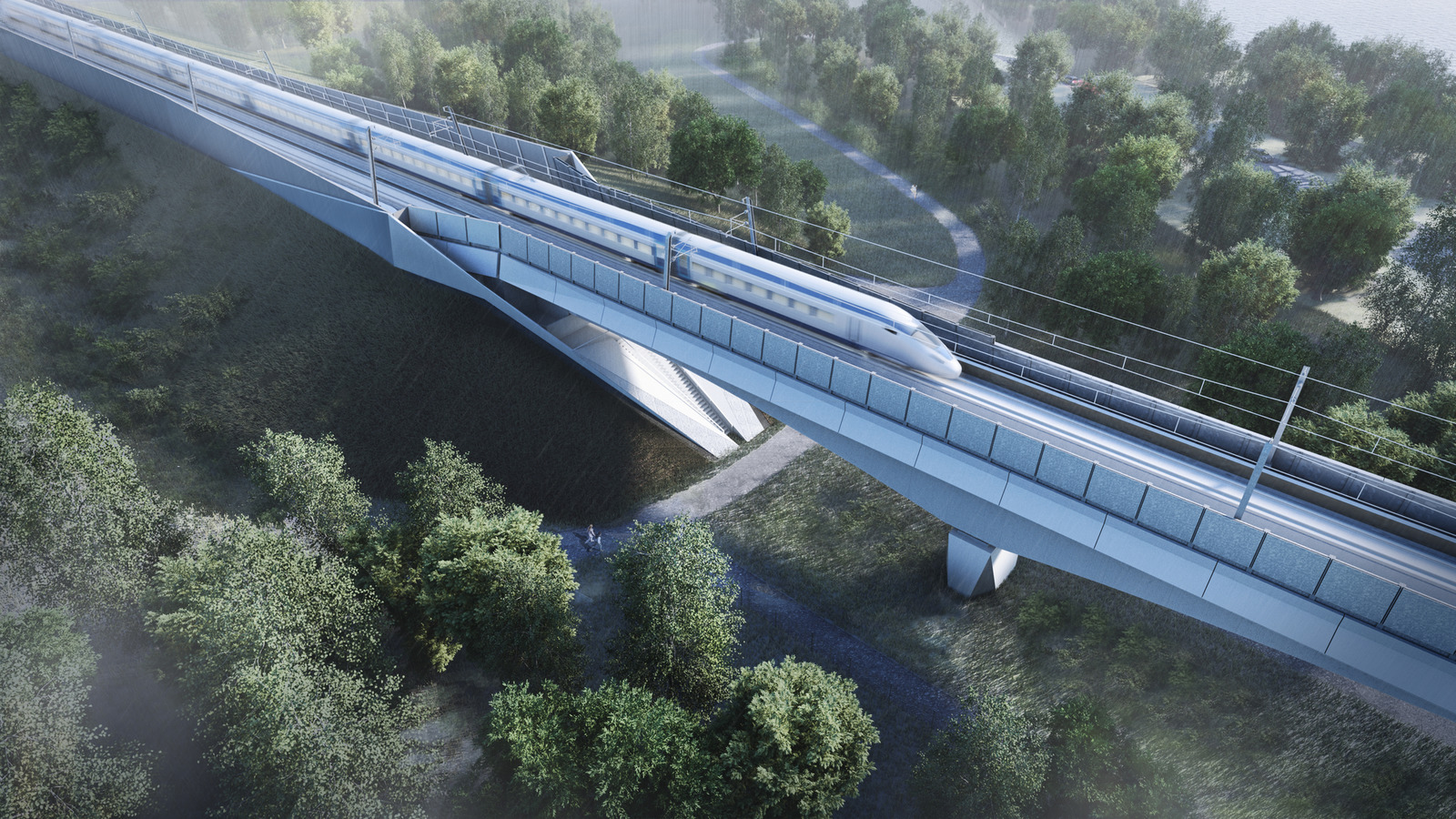
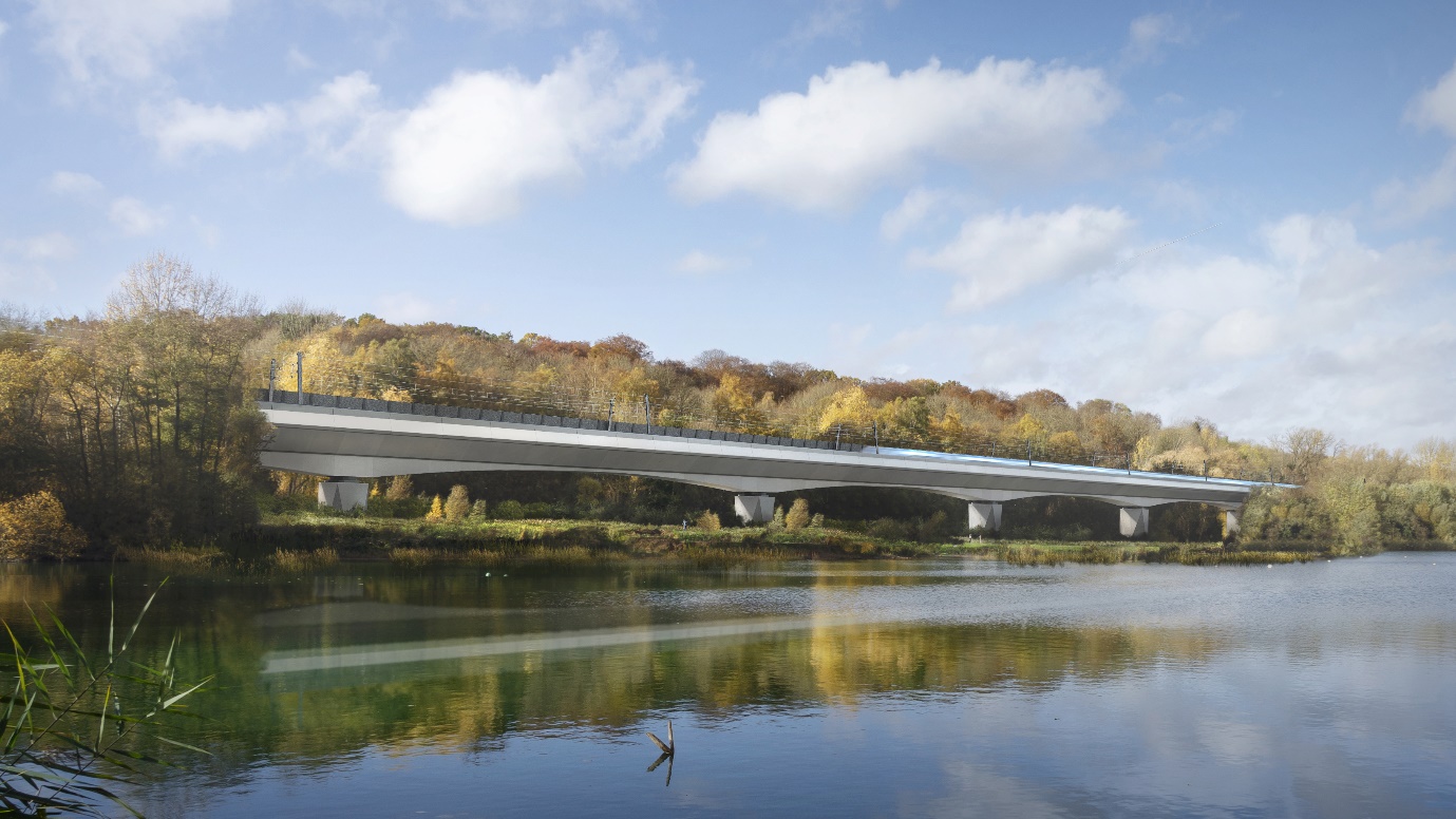
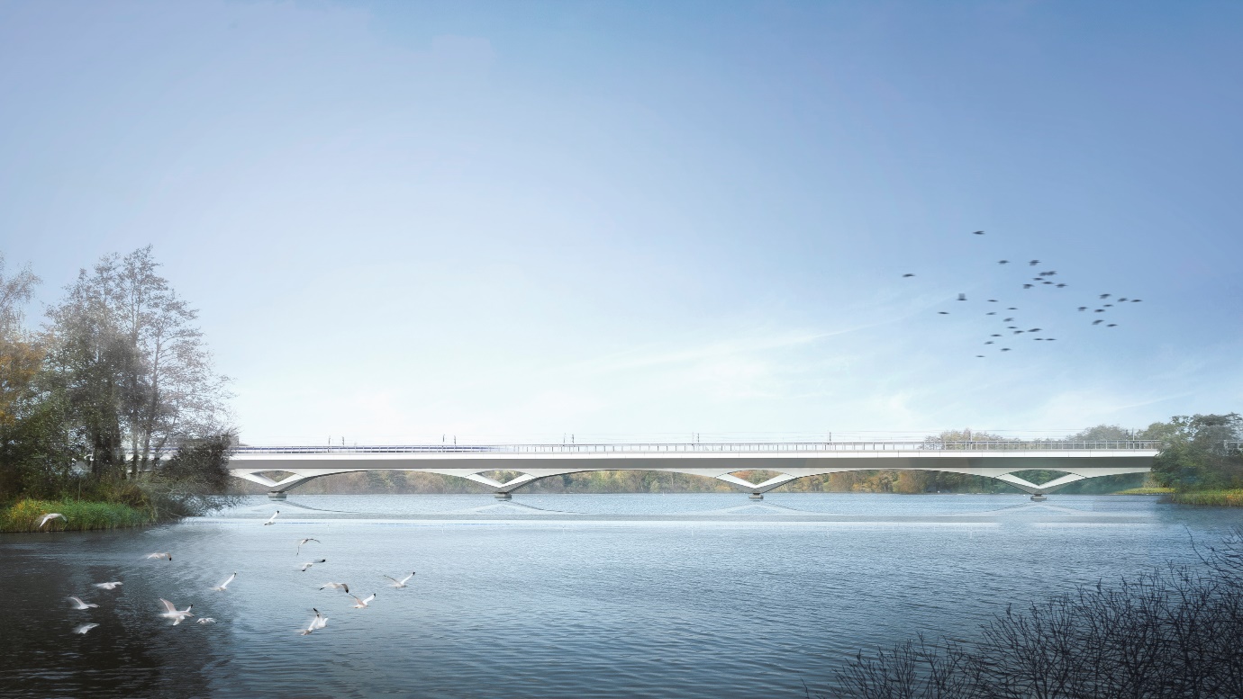
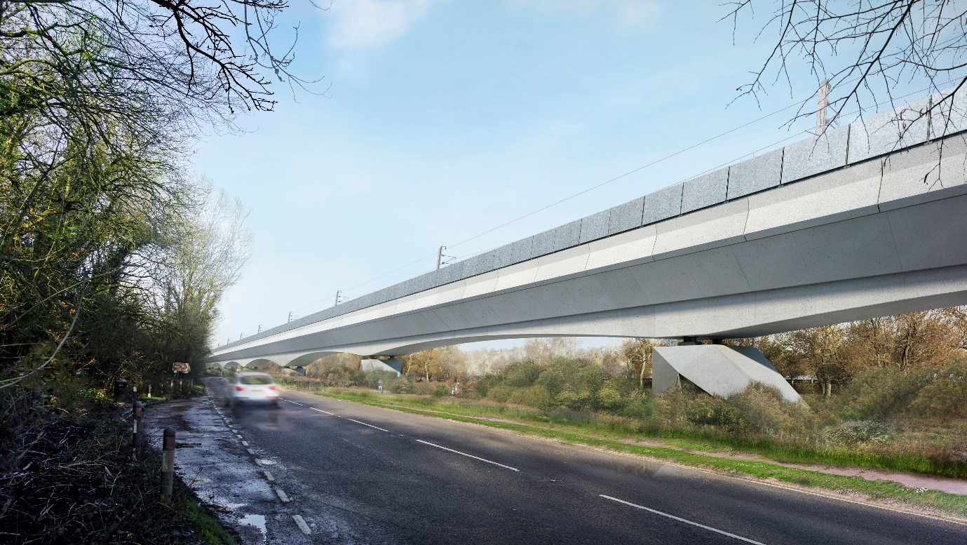
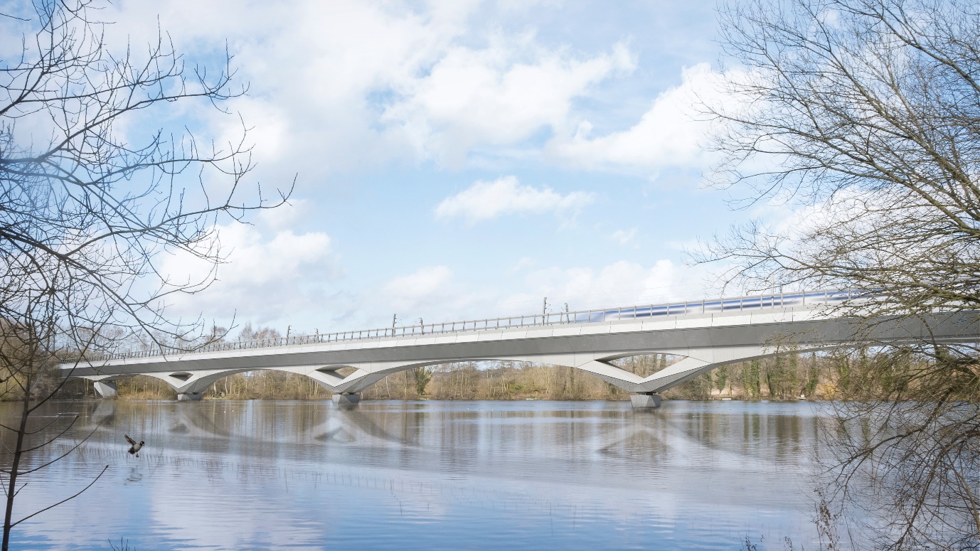
The Colne Valley Viaduct will be a key landmark along the route of HS2 Phase One, befitting its unique landscape setting. The 3.4km structure will be the longest railway viaduct in the UK and has been designed to meet demanding technical, environmental and operational requirements. A key challenge for the design team has been to balance these requirements with the needs and aspirations of the client and local community stakeholders. From the outset, the design process has been supported by extensive engagement to ensure key stakeholders appreciate the technical design parameters of high-speed rail and the importance of balancing aesthetic, structural, environmental and operational requirements. An integrated engagement and design process have been fundamental to achieving a cohesive design that responds positively to its sensitive landscape setting and satisfies stakeholders. Figure 1 shows a visualisation of the proposed design. The benefits of integrated design on the project are significant and can be exemplified through the following key themes: architecture of engineering; response to context; common design language; and noise barrier design.
Architecture of Engineering
Understanding the structural and technical principles of engineering for high-speed have driven the aesthetics of the viaduct structure. The resulting design celebrates the architecture of engineering: the structural form is an expression of loads, speed, function and construction, carefully crafted into a distinctive and elegant design – see Figure 2.
Structural Articulation
As with traditional railway construction, structures for HS2 will require expansion joints, to allow the 3.4km structure to expand and contract with changes in temperature. The viaduct is conceived as four modules that can move independently, with corresponding expansion joints in the deck structure and track required at approximately 900m intervals – see Figure 3.
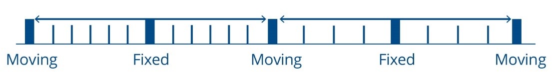
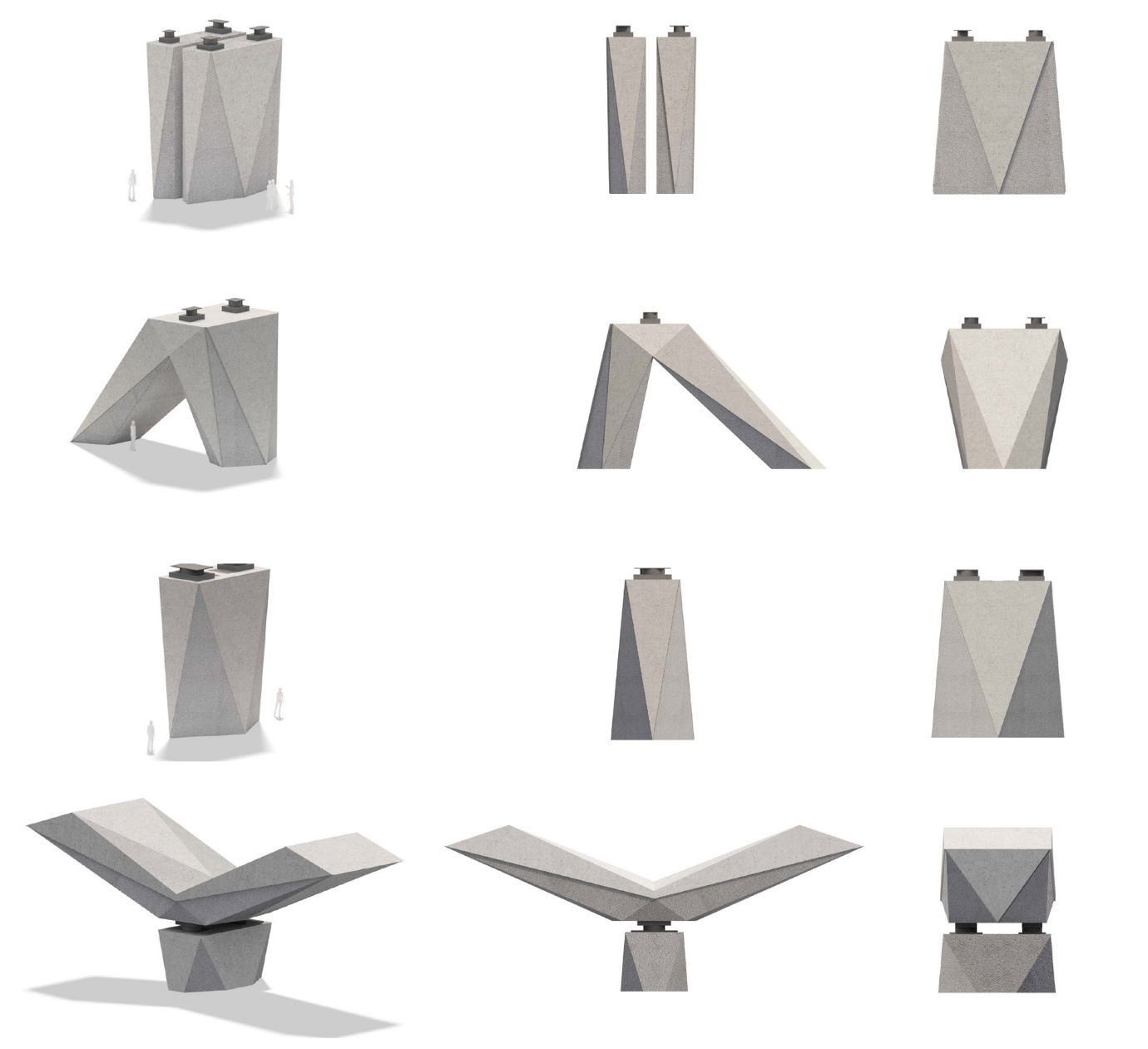
Each module therefore has a fixed braced stability ‘buttress’ in the centre and an independent structure supporting rail expansion joints at each end between each module. The structures at these locations are unique to these parts of the viaduct when compared to other piers, in both their function and form, visually expressing these locations as key features within HS2’s route through the landscape.
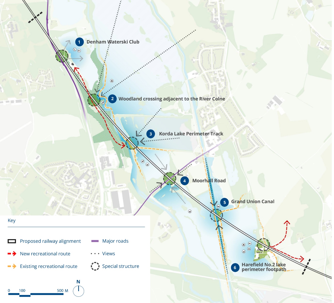
The architectural, structural engineering and construction teams ensured that these two types of special structures are strategically located at significant points within the valley, including HS2’s crossings of the Grand Union Canal and Moorhall Road – see Figures 4,5 and 6. By expressing these locations as special structures, the proposals established a combined structural and contextual logic that responds to specific features in the Colne Valley. Close collaboration with the landscape design team ensured that these conditions also define focal points for new and enhanced landscape features such as amenity areas and routes within the Colne Valley Regional Park.
Scale and Visual Mass
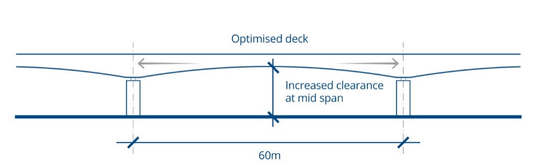
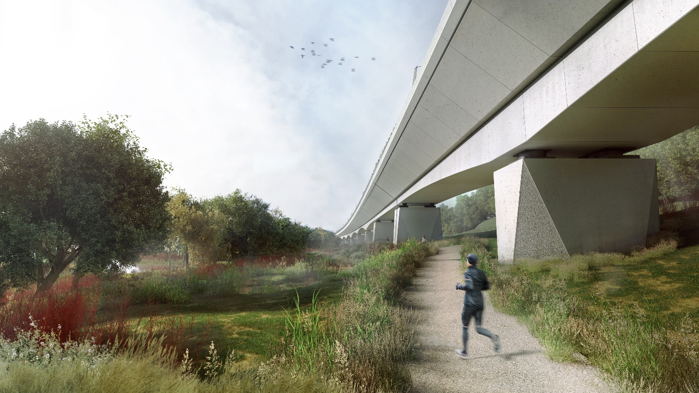
An unusual characteristic of the Colne Valley Viaduct is the low level of the tracks above the surrounding landscape. The proportions and scale generated by this geometry were a significant design challenge for the architectural and structural engineering teams. The low track level made it important to maximise headroom and opportunities for views of the sky and landscape underneath the viaduct. A significant benefit is gained by raising structural elements as high as possible above the ground, maximising views of the landscape beneath. The design achieves a balance between the more frequent supports of shorter spans and the increased structural depth necessary for longer spans.
Over the majority of spans the deck is haunched (see Figures 7 and 8) to provide additional depth over the piers, visually reflecting the forces acting upon the structure. This allows for a greater degree of flexibility in span, meaning that the location of supporting piers can be adjusted to suit their specific context in the valley. The continuous curved soffit profile within each haunched span was carefully refined through extensive and iterative 3d modelling of the deck by the architectural and structural engineering teams.
Structural Form
High-speed trains create substantial structural loads and the viaduct design seeks to balance challenging engineering demands with a refined and elegant design. Given the necessary scale of the structure, concrete forms have been crafted and faceted to reduce visual bulk where possible. This strategy has been refined by a crafted play of opposites: dark and light, rough and smooth, flush and recessed, further reducing the visual impact of the structure’s mass.
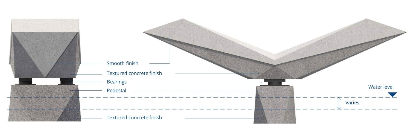
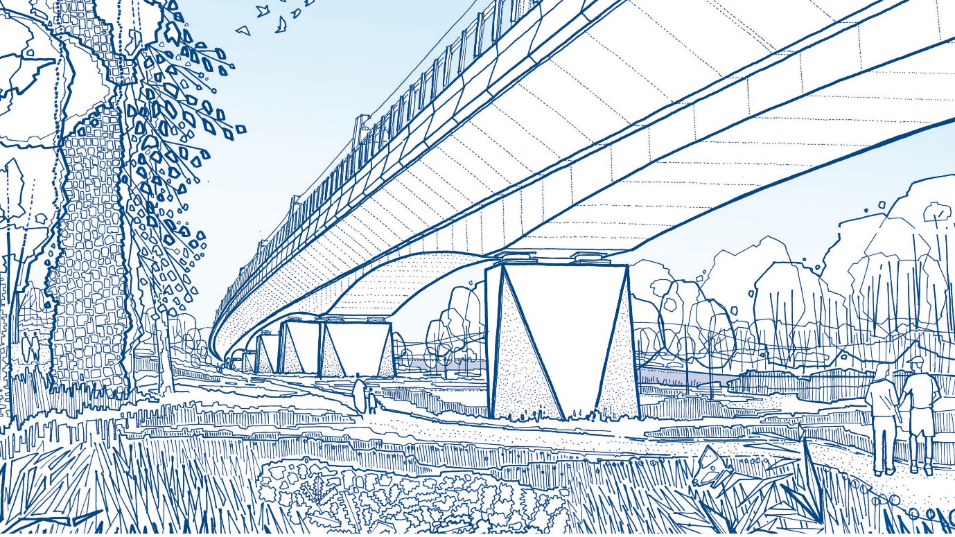
All piers use a common design language of folded triangular planes which alternate between smooth and textured surfaces. Pier forms are typically tapered at the corners, reducing their visual mass toward their base – see Figure 9. The use of textured concrete at low level reinforces this connection of the structure to the surrounding landscape, while the smooth finish at the viaduct soffit is continued onto the pier at high level.
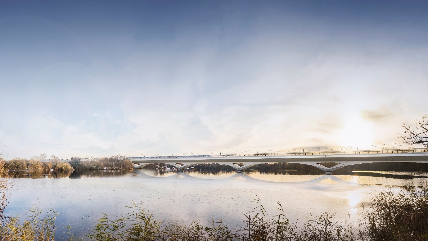
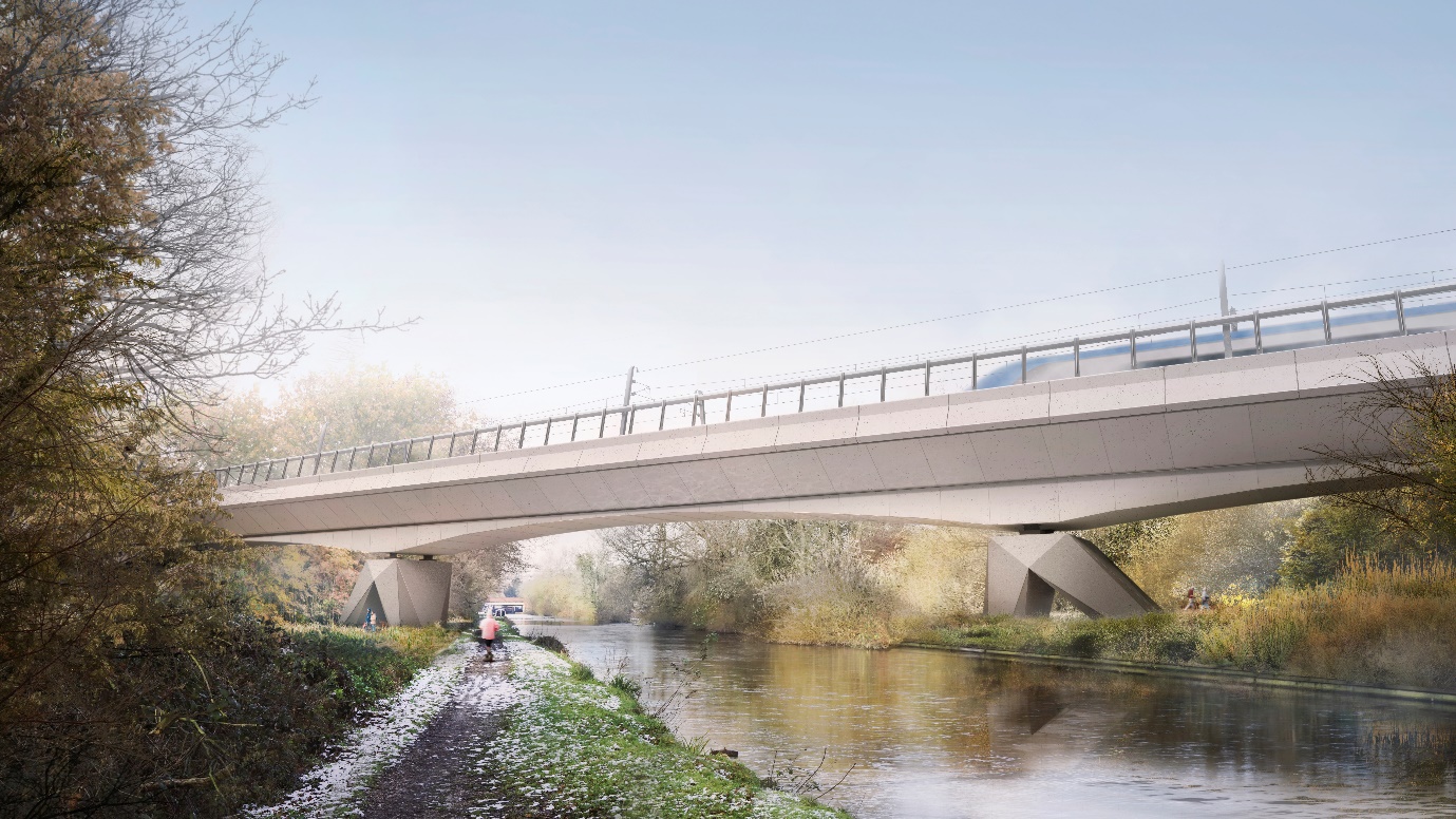
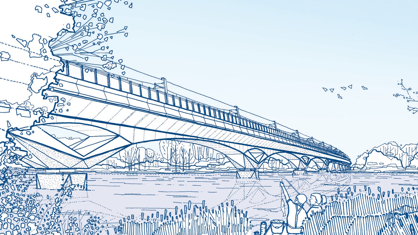
A key design driver for both the design team and local stakeholders has been to achieve a structure that skims lightly across the lakes, despite the huge structural loads, see Figure 10. The need to locate movement bearings to be located above flood risk levels had a fundamental impact on the span length that could be achieved over water and the geometry of the special supports. An integrated design approach between the architectural, structural engineering and construction teams enabled an elegant and refined structural form, with special focus on the rhythm of the spans and reducing visible mass of the structure.
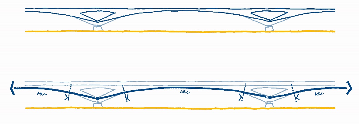
In order to achieve 80m spans over water, the inclined supports to the arch form deck structure are larger in scale than the standard piers. Combating this, sculpted concrete forms are used to manipulate light and shadow, defining a slender silhouette profile, see Figure 11.
Working with the maximum incline of the sloping supports, smooth visual continuity is achieved by introducing a tangent line from the end of the soffit arc to the centre of the V shape, well above the water’s surface. The resulting design creates a distinctive structure formed of a rhythmic sequence of low, slender arcs that skim lightly across the surface of the lakes, preserving landscape views across the water. Shadow and texture make the lower parts of the structure appear darker and visually recessive when viewed against the water and woodland beyond, see Figure 12.
Structural Deck
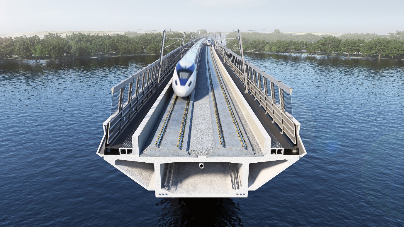
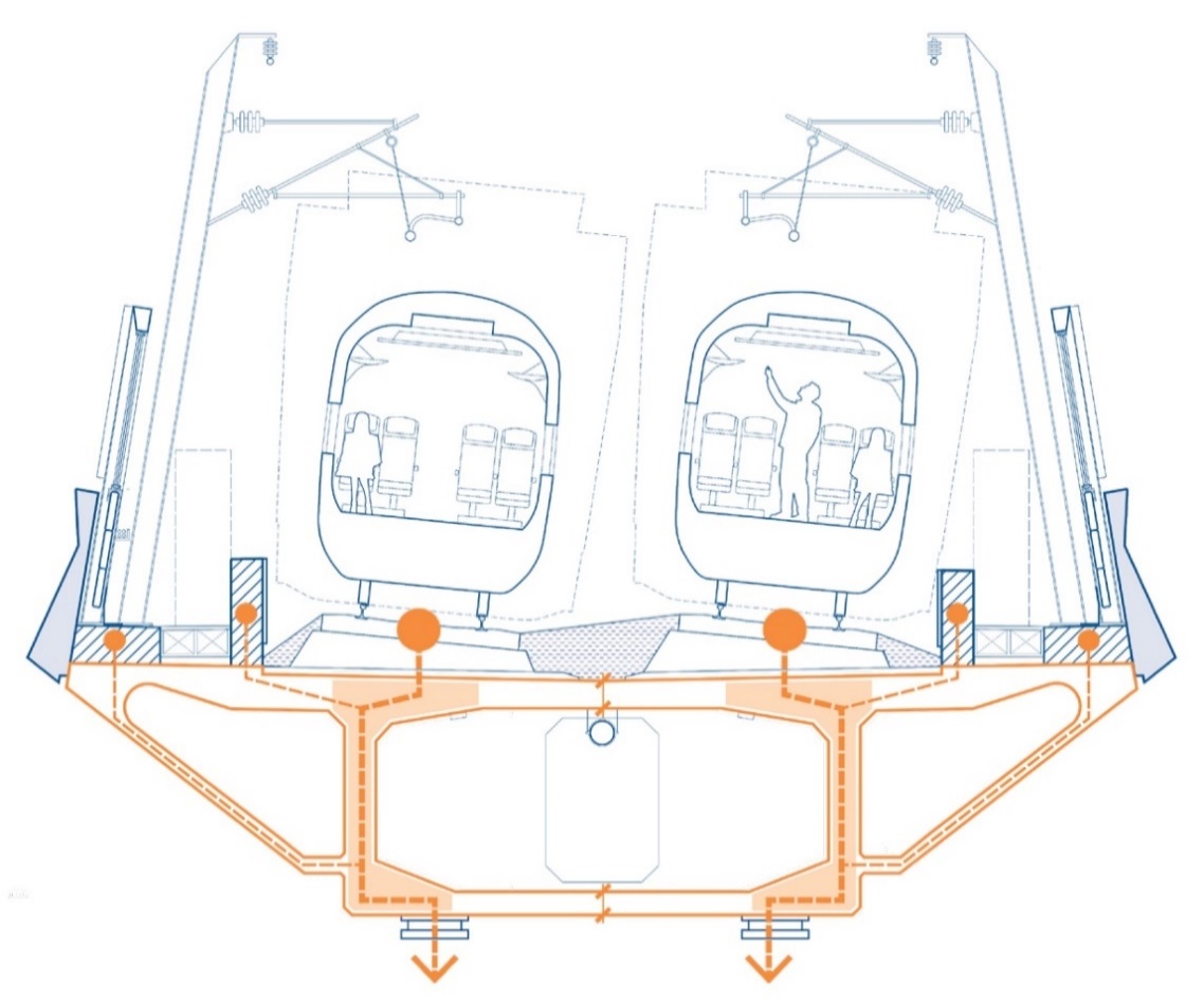
Another key focus for the design and construction teams has been to reduce the weight of the deck as much as possible. The variable depth box girder deck maximises structural efficiency by locating most of the structure directly below the track, with direct transfer of loads into the structure below, see Figure 13. By optimising structural efficiency, less concrete is required within the viaduct deck, resulting in a structure with less visual mass at deck level and a reduced deck width. The benefits of a lighter structure above continue into the supporting structure, resulting in smaller piers and reduced foundations. By reducing the quantum of concrete required structurally, views of the landscape and sky are maximised and significant carbon savings have been made.
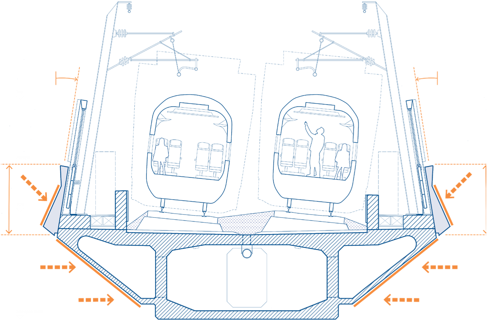
The play of light and shadow has then been used to manage how the visible mass of the upper deck structure is perceived. The shapes of the parapet and deck have been angled to pick up more daylight where desirable. Below the parapets, inclined soffits reduce the visible face of the box girder, particularly where haunches are deep at longer spans, see Figure 14.
The continuous concrete parapet provides a clean, simple and uninterrupted horizontal band along the entire deck structure. The geometry of the parapet is part of the common language of faceted forms used throughout the viaduct, see Figure 15. The profile incorporates a fold line to the upper third of the external face, breaking up the scale of the outer face and providing a slender band of shadow along the top edge, emphasising the long continuous horizontal line of the deck.
A specific challenge for the design team has been to reduce the weight of the parapets as far as possible. Ultra-high-performance concrete (UHPC) has therefore been specified, enabling a typical parapet thickness of approximately 60mm, minimising weight whilst maintaining the shape of the external face. An additional benefit is UHPC’s low porosity levels in comparison to typical concrete, which will assist in minimising the effects of weathering over time.
Response to context
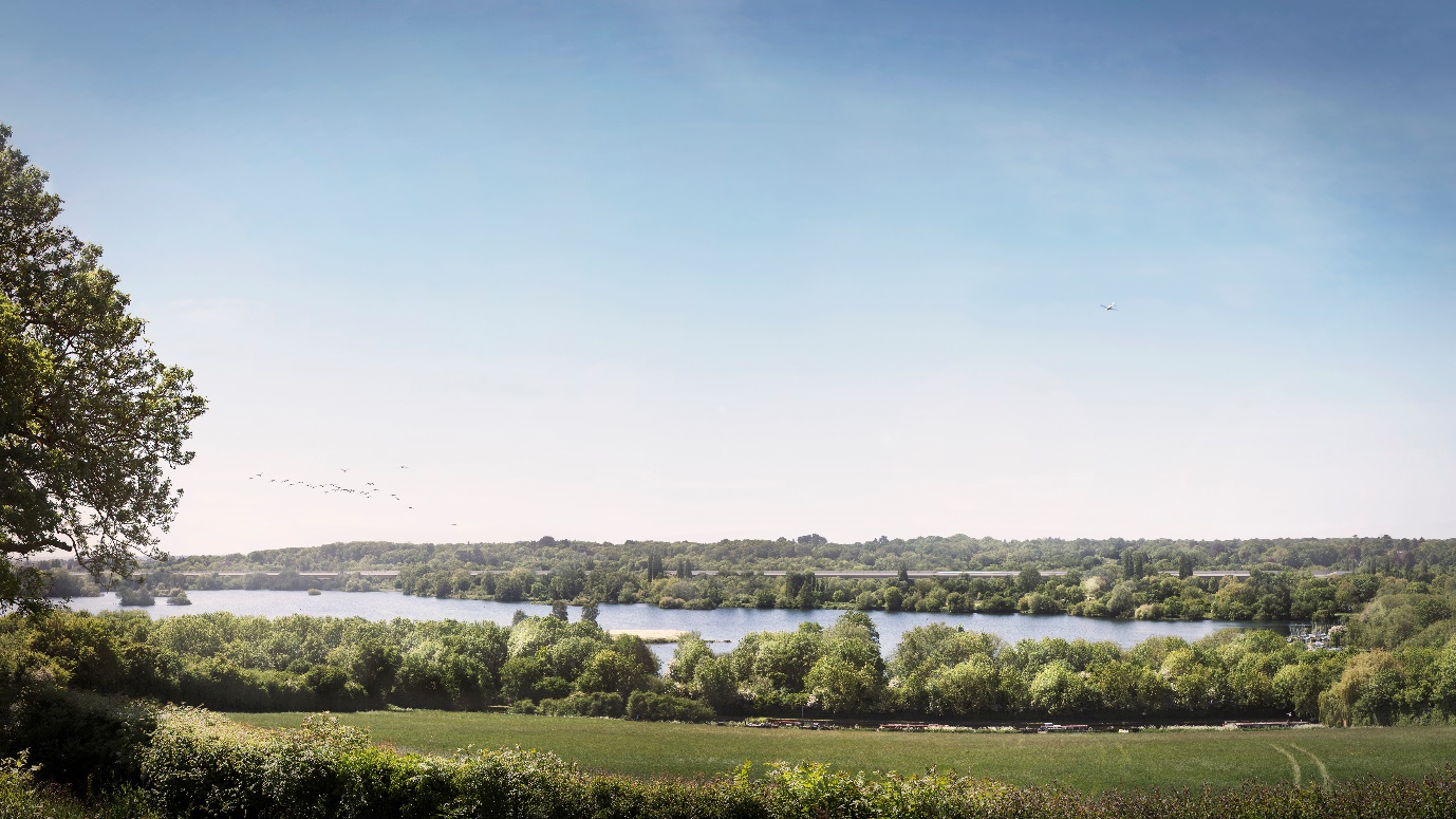
The Colne Valley is an attractive, highly valued landscape and has significant environmental sensitivities, including the designated Mid Colne Valley Site of Special Scientific Interest (SSSI), Local and National Nature Reserves, Local Wildlife Sites and Ancient Woodland, see Figure 16. A thorough analysis of the Colne Valley context was therefore undertaken by the design team at the outset of their work and has since informed integrated design proposals for both the viaduct and landscape design.
Landscape Integration
Landscape proposals have been developed to enhance the experience of both the Colne Valley Viaduct and its surrounding context. Critical to this approach has been the close collaboration between the architectural, landscape and environmental teams.
The landscape and ecology proposals conserve as much of the most sensitive habitats within the Colne Valley as possible. Central to this approach has been to reduce the viaduct construction corridor to minimise tree loss. Great effort by the structural engineering and construction teams has gone into reducing the deck width to the minimum practicable when considering train envelopes, derailment protection and maintenance access. Additionally, the design team worked closely with the construction team to carefully locate construction haul roads in order to retain key local landscape features such as the ancient woodland at Battlesford Wood.
The design proposals will also establish new landscape and wetland features, introducing habitats which have been lost or are scarce in the Colne Valley. These areas have been strategically located to complement the existing natural environment and enhance biodiversity.
Proposals have sought to deliver new recreational routes for walking and cycling which open new areas of Colne Valley Regional Park as part of a strategic rights of way network. Maintenance tracks required alongside the viaduct will also be used as recreational routes and have been located to enhance accessibility within the park whilst providing access to the viaduct structure, see Figure 9.
The woodland piers have been designed to provide further human scale interest through pattern and texture at low level. In locations deemed vulnerable to graffiti, textured concrete will help to deter graffiti, whilst landscape proposals include defensive planting to limit direct access to some of the piers.
Response to character areas
The surroundings of the Colne Valley Viaduct can be broadly defined as two character areas: woodland and water. The woodland areas are characterised by their sense of enclosure, with dense woodland and varied topography restricting far reaching views across the valley. The water areas are mainly large lakes which provide expansive open views towards the surrounding landscape around their perimeter. In order to integrate with this distinctive landscape, the viaduct is highly responsive to the different character areas.
The use of a variable depth box girder structure allows structural spans to vary as the viaduct passes through the mosaic of lakes and woodland. Longer 80m spans are achieved over water to preserve open views and the sense of landscape continuity beneath the viaduct, see Figure 17.
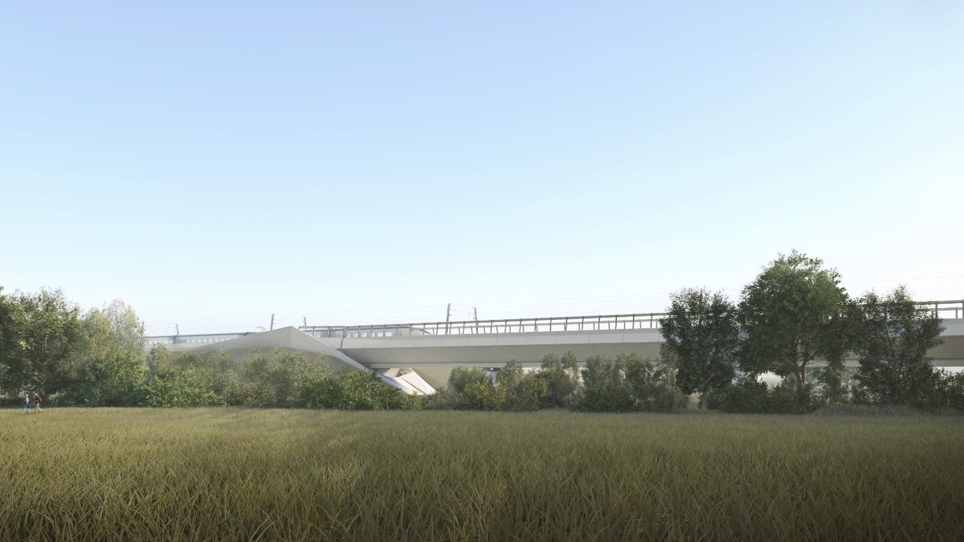
In woodland areas, shorter spans of typically 60m provide greater headroom beneath the viaduct, helping to maximise daylight and sunlight underneath the structure, see Figure 18.
Response to local features
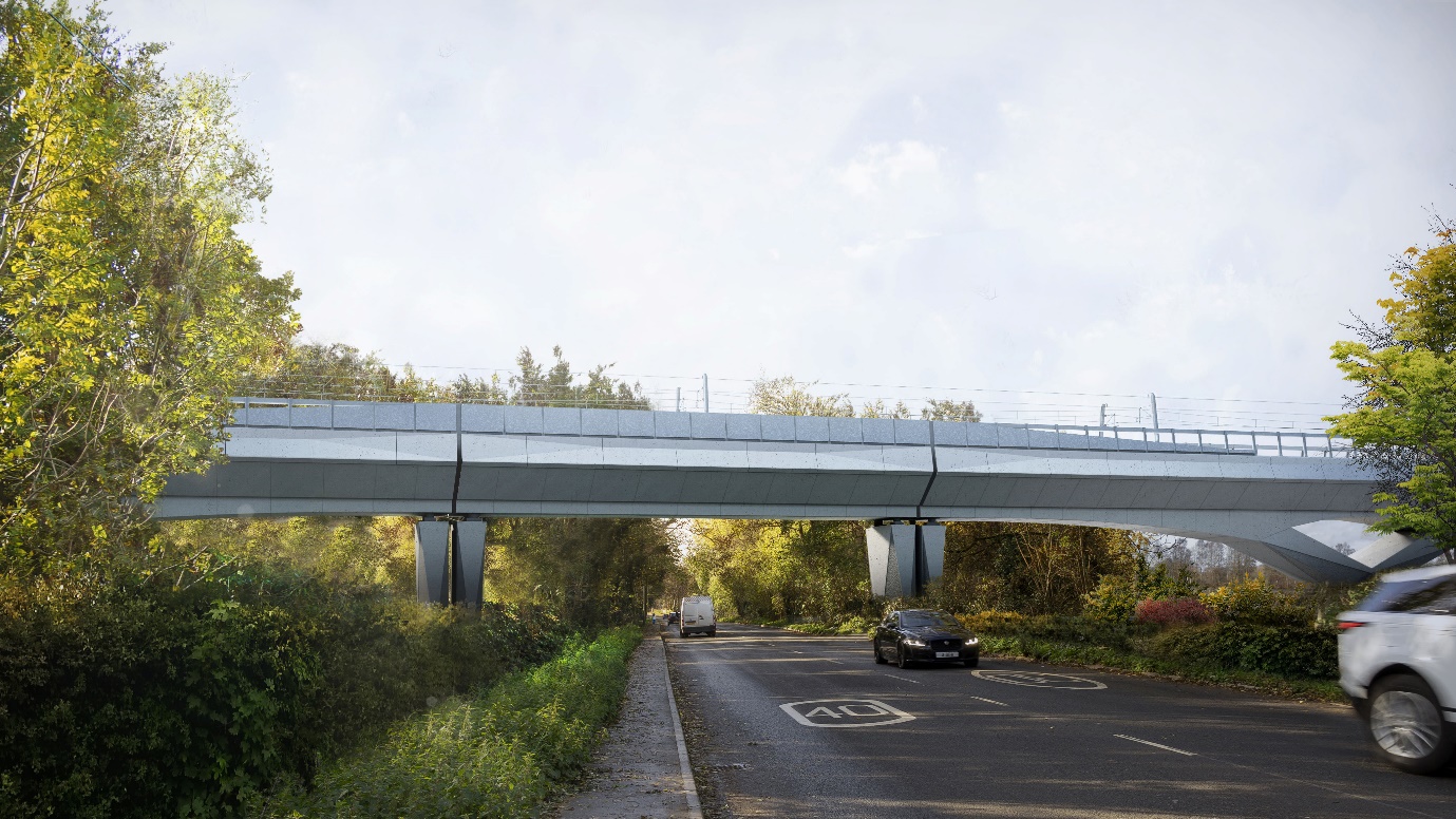
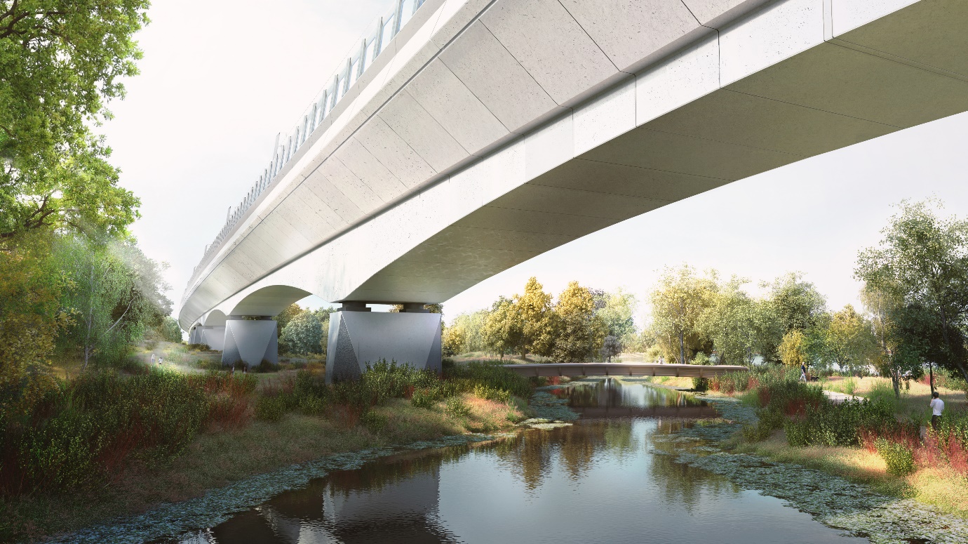
Due to the greater degree of flexibility in span length, pier locations have been carefully located to suit their immediate context, achieving a high degree of integration with the existing landscape. At the crossing of the A412, the span has been increased to 80m to ensure that piers are located on either side of the existing road, minimising impact on local communities during construction. An 80m span over the River Colne limits the need to realign the watercourse and associated ecological impacts on local wetland habitats, see Figure 19.
A common design language
To manage variations in technical and engineering requirements for structural components and railway systems, a common design language has been used to ensure the viaduct is recognisable as a single, coherent structure wherever it is experienced in the Colne Valley. This aligns the structural elements, parapet and rails system components as outlined below.
Structural Elements
Following close collaboration between the architectural and structural teams, a family of aesthetically unified structural components have been designed using a clear set of principles, see Figure 20:
• Geometry: Folded planes and straight edges characterise the form of structural components.
• Texture: A single textured concrete finish has been selectively applied to locations where the structure meets the ground.
• Edge conditions: Consistent edge detailing to concrete piers.
• Bearing offset: The bearing offset between pier head and deck soffit remains consistent throughout.
• Straight edges: Curvature is only used in the haunched deck profile and is formed by a continuous, shallow arc spanning between piers. All other structural components are characterised by faceted forms and defined edges.
• Materials: The ALIGN design and construction team are currently undertaking an extensive sampling process to ensure the colour and finish of all concrete components match as closely as possible. This is a significant challenge given the variety of structural components, many of which have differing specification requirements.
These principles were established by the architectural team early in the design process to ensure developing proposals remained consistent and integrated with the overall design vision for the viaduct.
Parapet
A concrete parapet forms a continuous, horizontal band along the viaduct. Its geometry is aligned with the deck soffit panels to ensure a streamlined and integrated appearance with the overall structure. This ‘datum’ line helps to mark the break between the structure below and the lighter weight systems above, while achieving visual continuity across the viaduct. Most of the parapet incorporates a fold line to the upper third of the external face. This breaks up the scale of the outer face and provides a slender band of shadow along the top edge, emphasising the long horizontal orientation of the deck. The parapet transitions to a triangular fold to mark the ends of the structural deck modules at all expansion joints. The geometry of the parapet is part of a common language of faceted forms used throughout the viaduct, helping to unify the overall appearance of the viaduct, see Figure 21.

Rail System Components
While the Overhead Line Equipment (OHLE) is procured as a route-wide contract, it remains a highly visible and important part of the viaduct design. The viaduct proposals have therefore been developed in close collaboration between the design team and HS2 Rail Systems. Design proposals indicate an achievable design intent for the setting out, form and appearance of the OHLE to provide a coherent and integrated design approach. All above deck components are specified as galvanised steel to ensure visual consistency and a similar change in appearance over time.
Noise barrier design
Noise barriers are required on both sides of the Colne Valley Viaduct in order to meet the acoustic requirements set out in the Environmental Statement (ES) and the hybrid Bill Undertakings and Assurances (U&As). As well as noise mitigation, other key design principles for the noise barriers were to reduce visual impact, enhance passenger experience and prevent bird / bat strike with passing trains wherever practicable. An integrated design approach to the noise barriers was critical to achieving an appropriate balance between these varying requirements, whilst achieving a coherent overall design.
Acoustic Modelling
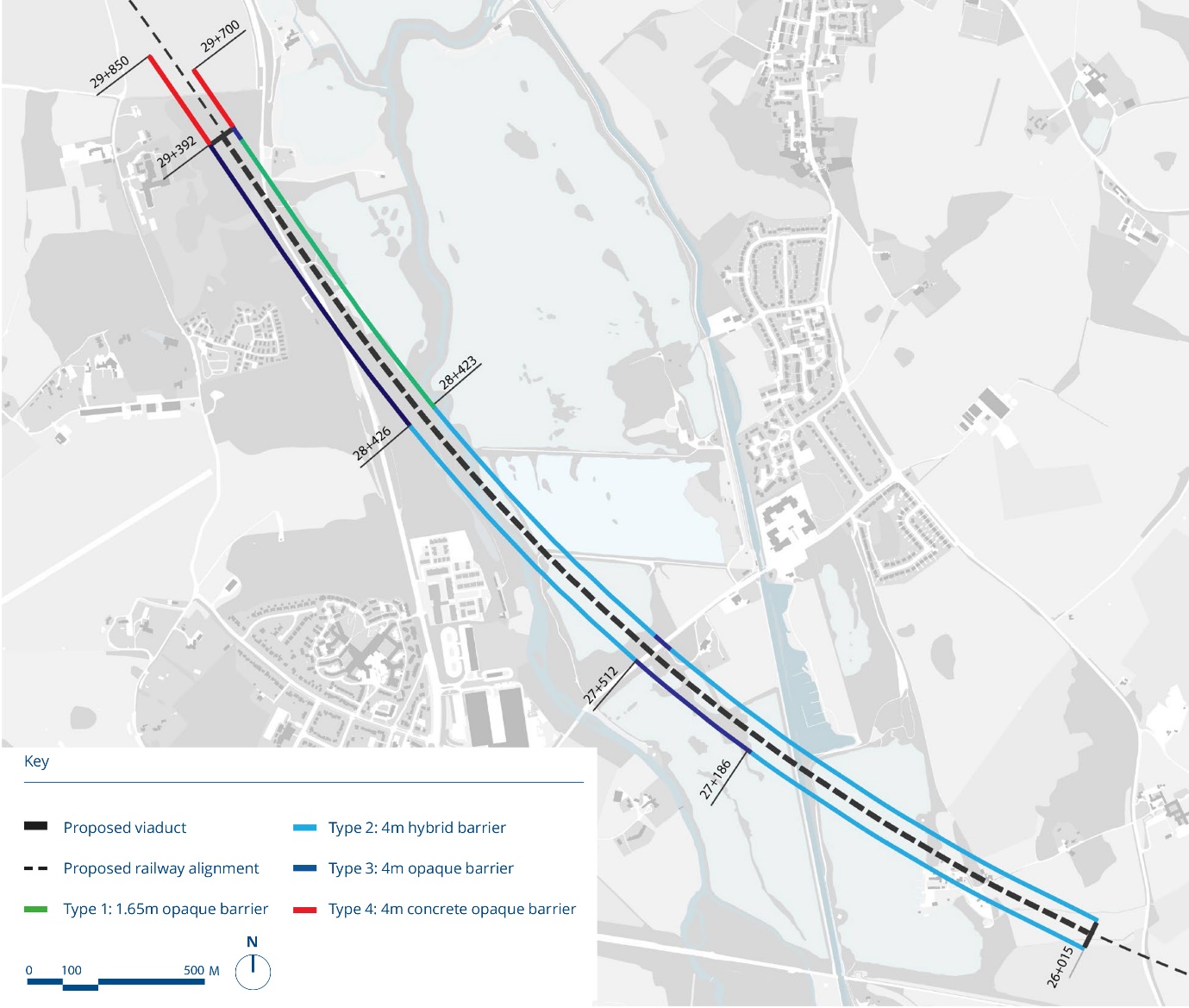
Extensive noise modelling was undertaken by the acoustic engineers based on rolling stock and track specifications agreed with HS2. Crucially, cross disciplinary design work was supported by iterative acoustic modelling of noise barrier options at different locations along the viaduct. Multiple geometries, heights and configurations of reflective and absorptive surfaces were tested in the acoustic model to identify optimum solutions. The acoustic modelling established that the noise barrier design needed to vary along the length of the CVV to respond to specific noise receptors, see Figure 22.
Noise Barrier Design
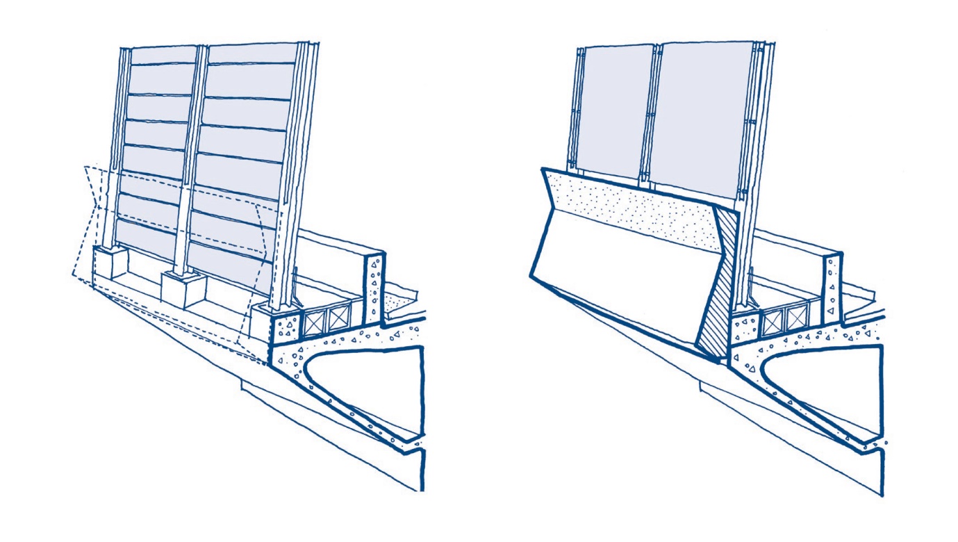
Early in the acoustic modelling process it became clear to the design team that inclining the barriers and locating them as close as possible to the tracks significantly improved noise mitigation performance. It was also identified that locating absorptive material at low level, close to wheel and train noise, helped to optimise noise mitigation.
Modelling results showed that a band of absorptive material was required at low level throughout the viaduct, up to at least 1.65m above top of rail (TOR). In some areas, close to residential receptors, the height of absorptive material on the noise barriers needed to increase to 4m (above TOR), see Figures 23 and 24. Acoustics and architectural disciplines in the design team assessed potential noise barrier construction, working in close collaboration with potential manufacturers. Standardised galvanised steel cassettes with a mineral wool infill and perforated inner face, were proposed for the absorptive parts of the barriers. To ensure the barrier did not appear to be an uncoordinated ‘off-the-shelf’ element, the cassettes are concealed externally by the continuous parapet at low level and large format galvanised steel sheets above, creating a simplified, streamlined appearance.
Wherever possible, 4m hybrid barriers are proposed along the viaduct, which incorporates a band of transparent acrylic panels above 1.65m, allowing passenger views out from passing trains and reducing the ‘solid’ scale of the viaduct in the landscape, see Figure 25. Extensive noise modelling was undertaken by the acoustic engineers to ensure that the visually lighter hybrid barriers could be accommodated at important and prominent locations, such as the lake crossings and Grand Union Canal.
The top edge treatment of the barriers was also critical to acoustic performance due to the proximity of high-level noise from the pantograph and catenary system. The 4m hybrid barriers therefore incorporate an opaque top band to provide an absorptive surface at high level. Detailed acoustic modelling enabled the design team to establish the minimum height of the top band to ensure the hybrid barrier appeared as light as possible. In some parts of the 4m opaque barriers, innovative top edge acoustic resonators were proposed to optimise the performance of the barriers where necessary. The resonator units are deeper than the noise barrier cassettes, so are located on the inside face of the barrier to ensure they are not visible externally.
Other Noise Mitigation Measures
In order to maximise transparency of the barriers, the design team needed to alleviate the acoustic performance requirements on the barriers. To do this, other possibilities for noise mitigation at rail level are being considered and assessed alongside HS2 Rail Systems, including using additional inner noise barriers, integrating the OHLE masts with the barriers and using an acoustically absorptive track slab. The design team are also assessing options for incorporating absorptive barriers between the maintenance walkway and tracks. Separate barrier systems close to the tracks were discounted due to the extent of aerodynamic loading exerted on them by passing trains. However, the concrete robust kerbs located either side of the tracks – primarily required to contain derailment – offered the opportunity to fix absorptive acoustic lining to the inside face. This enabled extremely effective noise mitigation at low level on the full length of the viaduct.
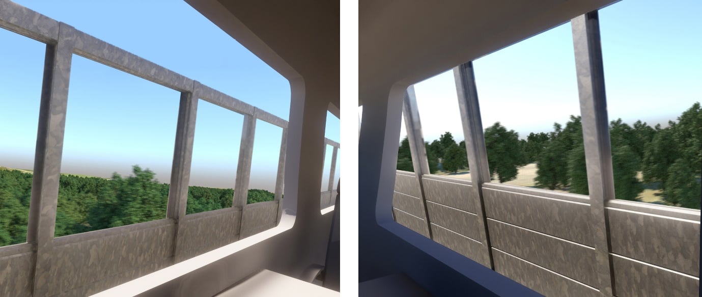
Passenger Experience
The architectural team produced animations to simulate the passenger experience from the trains, establishing the optimum field of view on both sides of the canted track along the full length of the viaduct, see Figure 26. This analysis established that to maintain an adequate view of the surrounding landscape, the solid part of the barrier should be no higher than 1.65m (above TOR). This level informed the configuration of the hybrid barriers, where 2m high by 3m wide transparent acrylic panels were located above 1.65m (above TOR). The simulation of passenger experience was used to review and agree design proposals with the HS2 Inclusivity team.
Ecological Impact
Due to the location of the Colne Valley Viaduct within a highly sensitive natural landscape, the risk of bird and bat collision with passing trains was considered as part of the noise barrier design. The design team worked closely with potential manufacturers to ensure the noise barrier design mitigates impact on local ecology, as well as the achieving acoustic requirements set out in the ES and U&As. The proposed 4m (above TOR) barriers provide effective enclosure to the train corridor, whilst the transparent acrylic panels incorporate black lines to ensure they remain visible to flying birds.
Conclusion
As demonstrated through the themes of ‘architecture of engineering’, ‘response to context’, ‘common design language’ and ‘noise barrier design’, the benefits of integrated design on the Colne Valley Viaduct have been significant and multi-faceted. An integrated cross-disciplinary approach to design and engagement has resulted in a design that successfully balances client and stakeholder aspirations with the challenging technical, environmental and operational requirements of high-speed rail. By establishing a robust and coherent design vision for the Colne Valley Viaduct, the design team have enabled innovative and integrated design solutions to a host of different design challenges. This design approach has meant that each component of the viaduct ‘works harder’, seeking multiple functions and benefits. As a result, the overall design of the Colne Valley Viaduct is distinctive, cohesive and highly responsive to its sensitive landscape setting.
Acknowledgements
Key Stakeholders / Consultees
HS2 Independent Design Panel
Colne Valley Regional Park Panel
Canal and River Trust
London Borough of Hillingdon
South Bucks District Council
Peer review
- David Smith, Lead Civil Structures EngineerHS2 Ltd