Using 3D models and BIM for the Chiltern Tunnel Design
Building Information Modelling (BIM) has been adopted for the design and build of the 16km Chiltern TBM Tunnel as part of the High Speed Two (HS2) project. A complete set of 3D structure models including two portals, two bored tunnels, five intermediate shafts and 40 cross passages is a key deliverable to HS2, as it will form the basis of all future asset management systems.
BIM is being used to store and manage design data in a Common Data Environment (CDE) and 3D models, allowing sharing, cross referencing and maintaining historical revisions. The BIM team uses the 3D models created for the project to create the engineering and construction drawings using dynamic views. This means any changes of the 3D models will be captured and automatically updated on 2D drawings, making drawing production more accurate and effective.
This paper discusses the advantages of using 3D models for design interface coordination with other design teams including clash detection, and how 3D models helped the contractor to assess the feasibility of different construction method options and prevent potential construction issues.
Introduction
Building information modelling (BIM) is a visualisation-based process that provides Architecture, Engineering and Construction (AEC) professionals the tools to enables data management and design coordination during the entire lifecycle of a project.
BIM has been widely acknowledged and increasingly adopted by the AEC industry in the recent decade. A comprehensive BIM with 3D modelling approach has been implemented throughout the design phase of the 16km Chiltern Tunnel.
The Chiltern Tunnels are part the central section of High Speed Two (HS2) Phase One – Lot C1 – which also includes the Colne Valley Viaduct, being delivered by the ALIGN Integrated Project Team.
Chiltern Tunnel consists of a twin TBM tunnel, five intermediate shafts, 40 Cross Passages (CPs) and a portal at South and North end of the tunnels. The section of the project has been divided into different packages. The authors have been involved in the Package 4 delivery, including the TBM tunnels, 38 out of 40 Cross Passages and the adits associated to each shaft.
Creation of 3D models
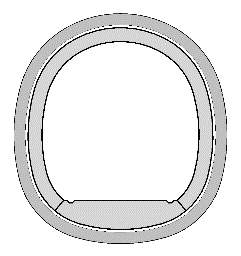
A 3D model was created for each structure within the scheme. Before creating the 3D models, 2D cross sections were developed to suffice all the space proofing requirements and structural checks. These 2D sections were also used to verify the 3D models as part of the QA process, by comparing with the cutting sections through 3D model.
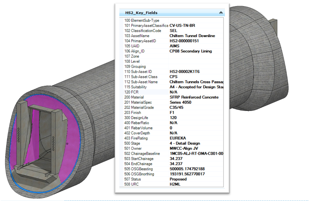
The following three main modelling techniques were used to create the TBM and CP models and define HS2 metadata (Figure 1) to each element:
DataGroup Catalog profiles
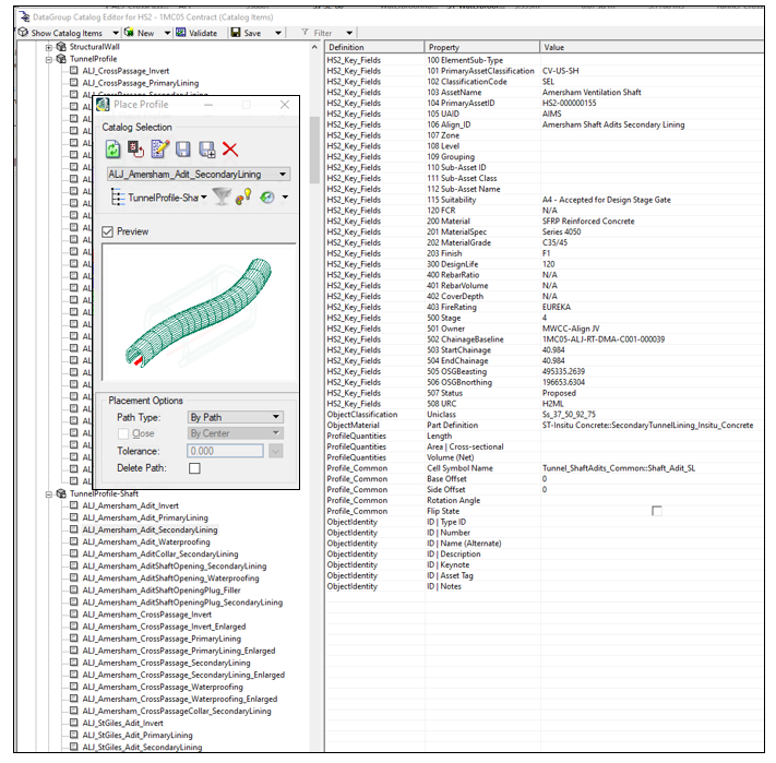
Catalog of elements were created for each space proofed 2D cross section. This allowed implementation of HS2 metadata before creating models. The modeller picked up the required shape from the Place Profile library and extruded it along the alignment or any predefined setting out line. This technique simplified the modelling process and avoided mistakes from manual creation/insertion objects along sometimes complicated 3D setting out lines. Metadata could be easily edited from inside the model after the model was created. See example in Figure 2.
Feature modelling
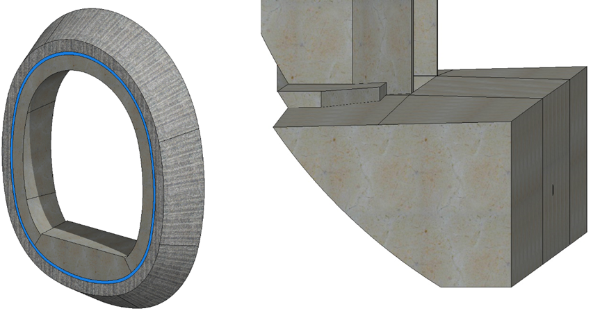
Feature modelling is an AECOsim modelling technique used to create complicated 3D objects with the benefit of maintaining the history of changes. Disadvantage is that there are no properties embedded from DataGroup Catalog, hence HS2 metadata must be added to objects in a different way. This technique was used for the Cross Passage collar transition and TBM tunnel walkway transition at door frame locations (Figure 3). HS2 metadata were later added to feature elements by Boolean operation. Boolean operations allow to combine objects, create the difference between two objects or create an intersection, and by intersecting a feature modelling object with a wall or slab (elements containing metadata), we were able to inherit required properties.
Generative components for TBM Ring model
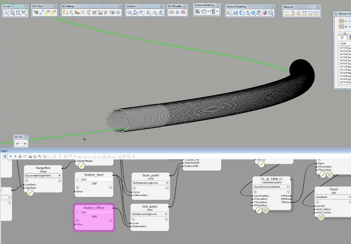
Modelling 16km long TBM tunnels introduced a new set of challenges. DataGroup technique only proved to be useful to create extruded elements up to a maximum 200m. Above this value the software was approaching its limits. The tunnel alignment had to be divided into maximum 200m long parts and used as individual setting out lines to extrude longitudinal elements like walkways, slab, or tunnel lining. The TBM tunnel lining comprised of 2m wide pre-cast concrete segmental rings. It would be a time-consuming task to divide each 16km long tunnel into 200m sections to model with DataGroup technique. In order to create more than 8,000 segmental rings over the entire length of tunnels more efficiently, computational design has been implemented via Generative Components (GC) software to build the TBM model (see Figures 4 and 5). This technique allowed the modeller to create a set of rules, which govern the automatic model creation. The full 16km length of alignment used as setting out line, a single ring as object and a pre-defined set of rules allowed to replicate rings with precision and control. Another benefit of GC was the ability of automatic data input to each element, but this software feature did not perform as anticipated, and data cannot be replicated into reporting schedules. Feedback was provided to the software developer who is now working on resolving this issue.
Design interface coordination
One of the biggest advantages of using 3D models is to coordinate the design with other disciplines. The Chiltern Tunnel design interfaced with shafts, portals and utility design. Different disciplines had their own 3D models developed for the design, and design coordination models can be easily prepared by bringing different 3D models from different disciplines into a federated model. Coordination of models can be shared across packages on the ProjectWise to be visible to all the relevant teams. Engineers were able to study the coordination models and identify interface issues. With the aid of Coordination models, interface issues can be visualised and discussed in the regular interface meetings.
Coordination of utility and service design
The design of the Cross Passages adopted an innovative design approach of using Reinforced Concrete (RC) door frames inside the TBM tunnels to provide support to the opening on the TBM segmental linings. With the door frames structurally connected to the TBM linings at each CP location, the route of the services and utilities running along the TBM tunnels needed to be agreed to by-pass the door frames or feed into the CPs as required.
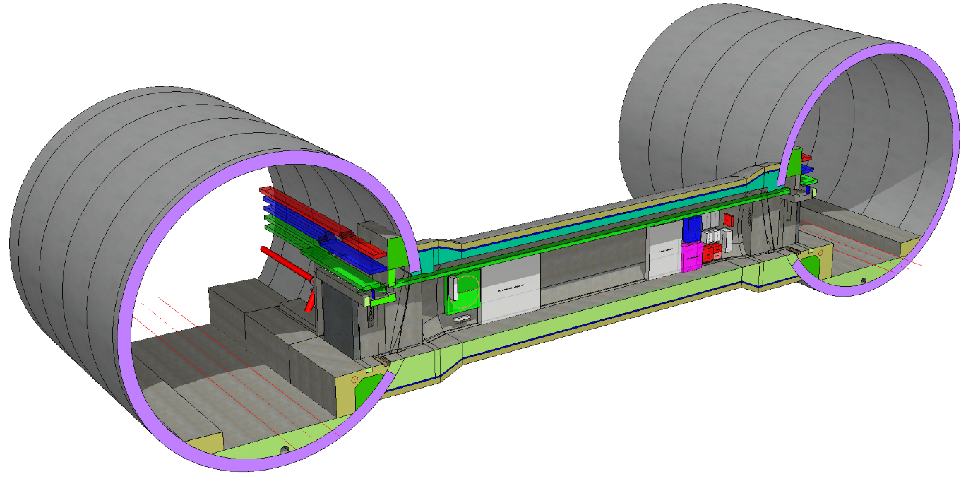
After the 3D models of the TBM and CPs had been created, they were shared to the tunnel Mechanical and Electrical (M&E) team and drainage team for design coordination purpose. The other designers could use them to create their own 3D models for their design elements such as cable ducts, fire mains, and drainage channels. All 3D models were then shared and referenced in a federated design coordination model (Figure 6). Thus, designers could always see the latest design developments from other design disciplines and conduct necessary design coordination. The responsibility was also clear as each discipline was responsible for keeping its own model correct and updated. When design coordination required recesses and openings to be modelled on the tunnel structures, solid blocks were modelled by the proposing party to represent cut-out in the concrete. The tunnel designer would then use the solid blocks to cut their structure models upon agreement between the designers. To ensure the coordination was carried out smoothly, it was important that a RACI (Responsible, Accountable, Consulted, Informed) chart was agreed between different parties on their modelling scopes.
Use of 3D model for construction method assessment
The designers used BIM to help the contractor to select suitable construction methods. Benefitting from the ECI (Early Contractor Involvement) approach, the contractor had been involved in the design development from an early stage. As an integrated design team, 3D design models were available to the contractors to help them understand the design approach and assess the feasibility of different construction methods.
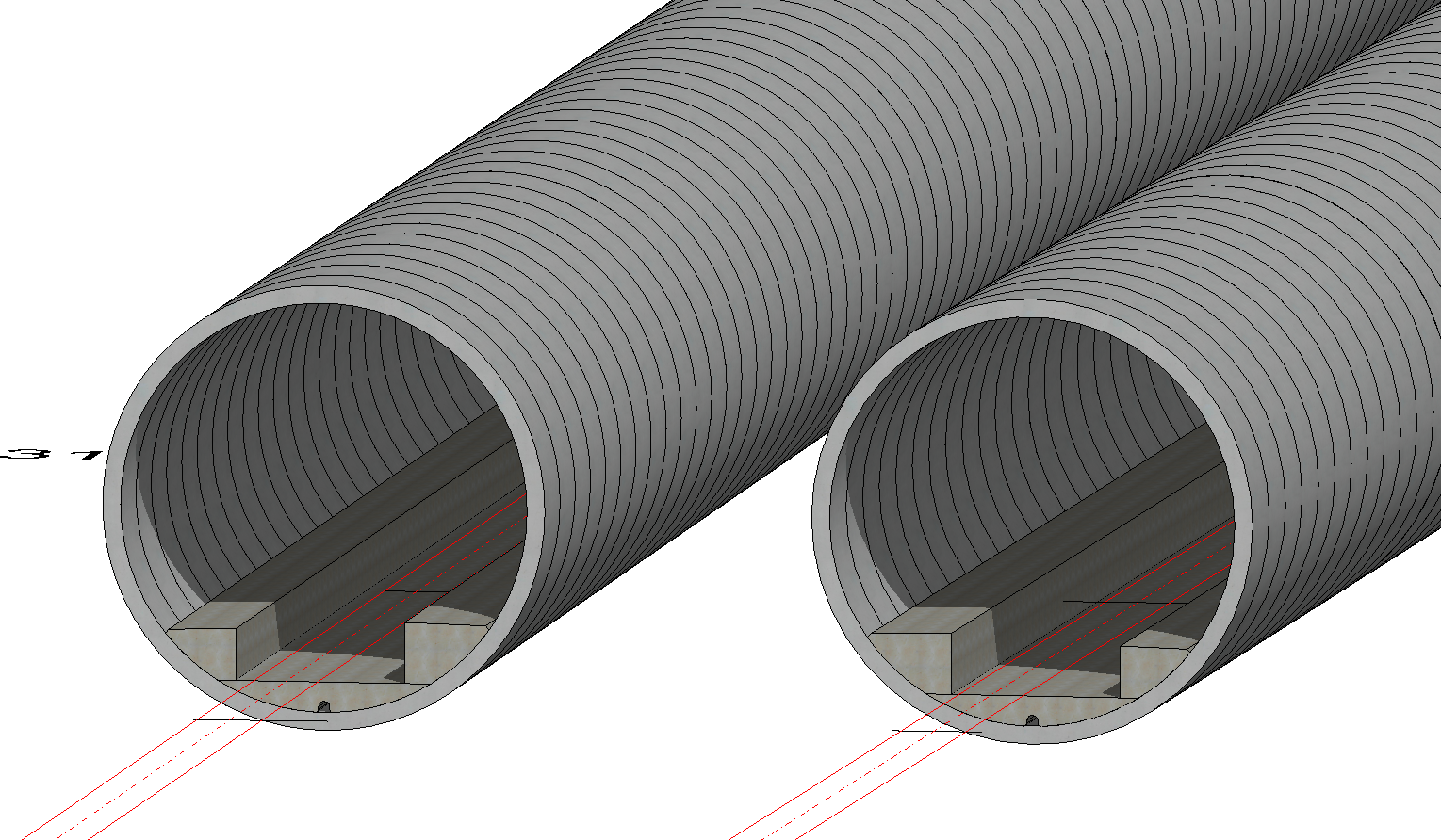
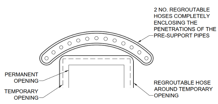
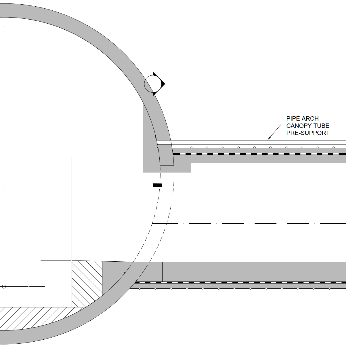
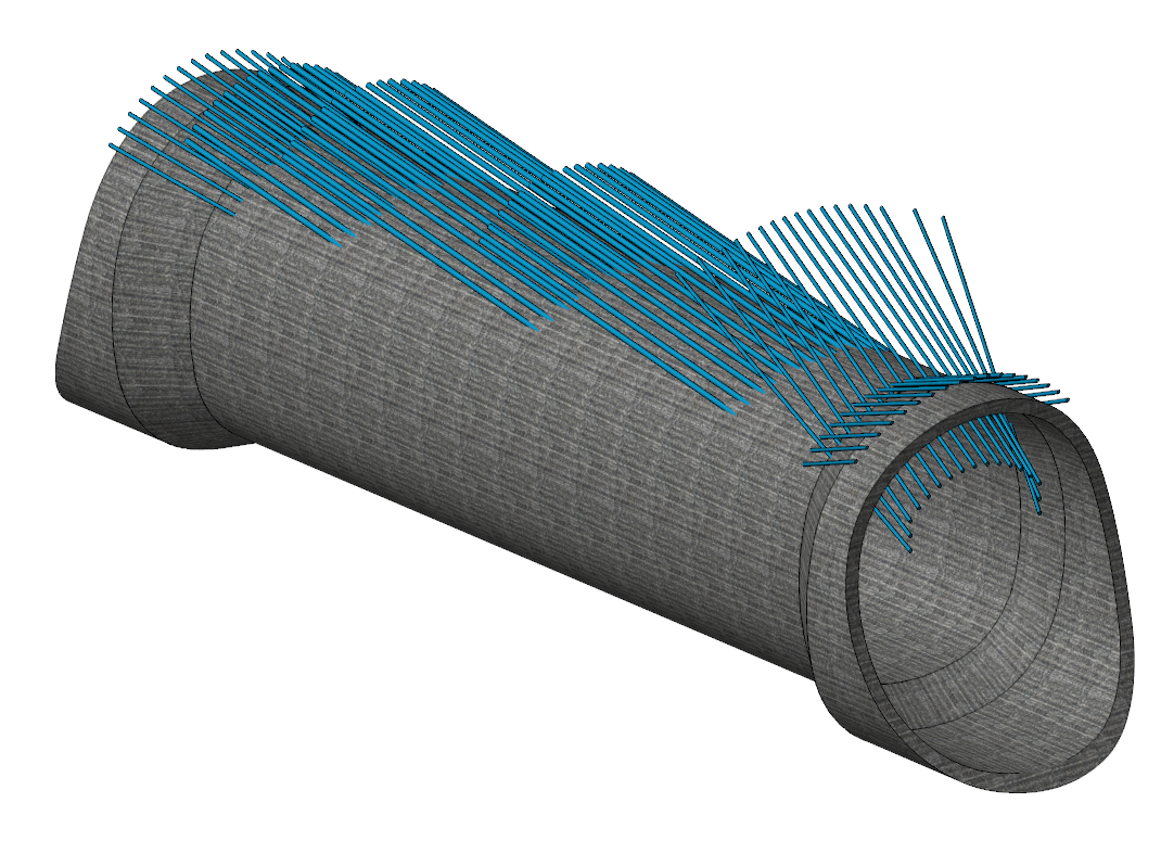
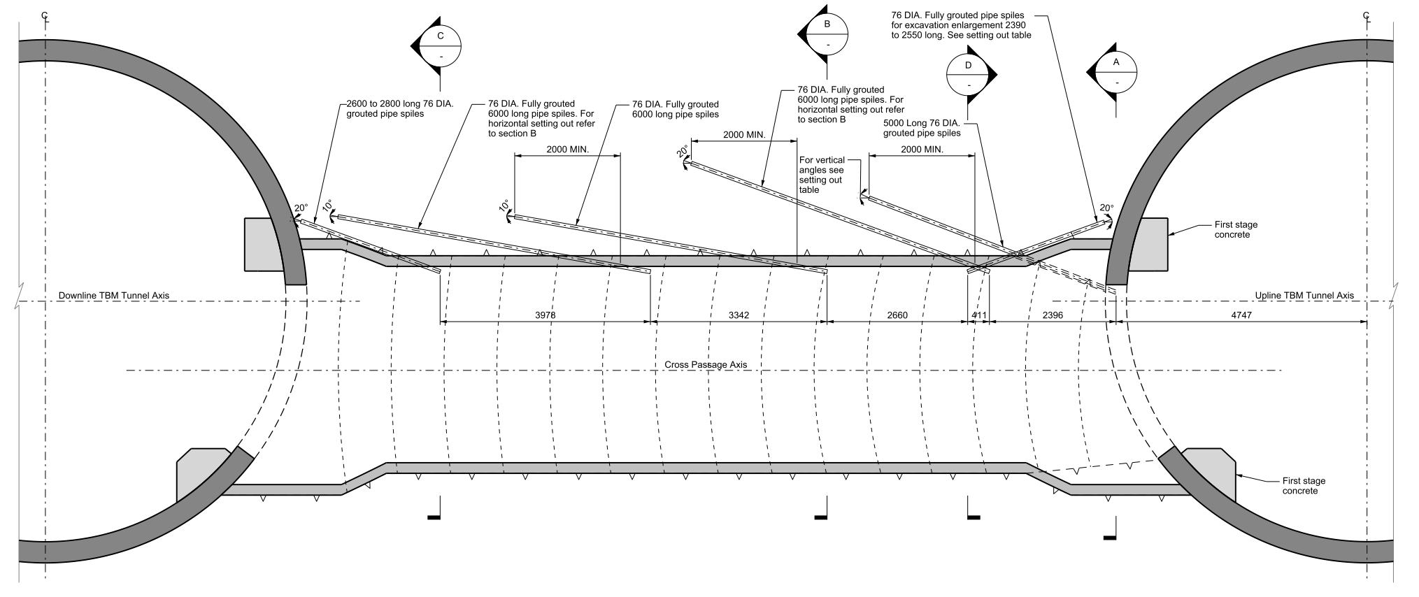
In the Scheme design stage, the proposed pre-support design for CP excavation was to install pipe arch canopy tubes (as shown in Figure 7) from the TBM and provide crown support throughout the excavation. After adopting the door frame support approach, as mention previously, a 3D federated model of TBM, CP and door frame was jointly reviewed by the designer and the contractor. It was identified that the pipe arch canopy tubes approach was no longer feasible due to the heavily reinforced RC frame around the opening. An alternative design of grouted pre-support spiles was considered. Although 3D modelling of temporary works was not required by the client, a full 3D model of the pre-support spiles system was conducted for space proofing and feasibility study purpose (Figure 8). The proposal was reviewed and subsequently accepted by the contractor, benefiting from 3D model.
BIM made it easy to extract and monitor the material quantities from well-established models with a great amount of accuracy, hence helped the contractor to estimate the cost more accurately. For example, the concrete quantity of the walkways inside the entire length of the tunnel could be easily extracted from the walkway models. The quantity would be updated instantly as the walkway profile was updated during the design development. With the embedded reinforcement density attribute in the BIM, the contractor could estimate the total reinforcement steel tonnage with reduced effort.
Use 3D model to produce design drawings
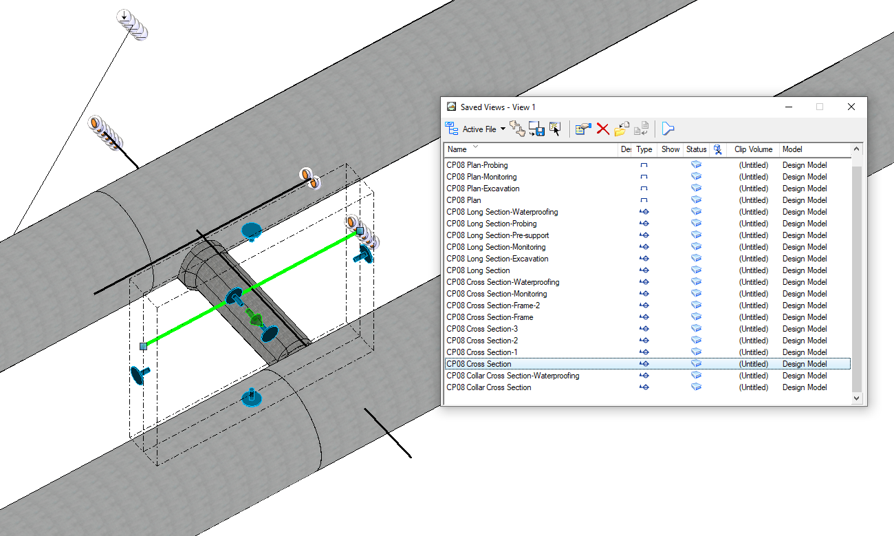
3D models were used to prepare the design drawings. Sections and views on the drawings were generated by creating dynamic views (D-views) at the specific locations on the 3D models. These D-views were saved in a separate D-view model and referenced to the drawing sheet with annotations and notes required to complete the drawings. Figure 9 shows the D-views set up in a CP 3D model with the highlighted D-view displayed in the small window.
Sometimes line types and hatchings needed to be manually adjusted at the D-views to improve the clarity of the drawings. An element from D-views could be selectively shown to fit the drawing purpose. For instance, only the primary lining was shown in the excavation sequence drawings while the secondary lining was turned off from the D-view. (Figure 10)
Once the drawings were set up with the correct D-views, it was much more efficient to update the drawings when the 3D model was updated as the design developed. Draftsmen just needed to refresh the D-view model to pick up D-views from the most up to date 3D model, the sections and views in the drawing were updated accordingly. The number of D-views increased as more drawings were produced. It was important that a coherent naming system for the D-views be used from beginning. Superseded or unused D-views should be deleted or renamed accordingly to avoid the development of too many D-views. Draftsmen spent too much time finding the correct D-view for a drawing which subsequently affected the efficiency of drawing production. A good D-view name should contain detailed location information and which drawing it was used to help the draftsmen select the correct the D-view during drawing production.
3D models should have enough detail so that the correct information is portrayed on the 2D drawings, it was important that a balance between insufficient details and too many details was maintained during the production of 3D models. Models with insufficient details would not provide the contractor enough information to understand the designer’s intent. Models with too many details were slow to model and could be confusing and distracting from the focus subject.
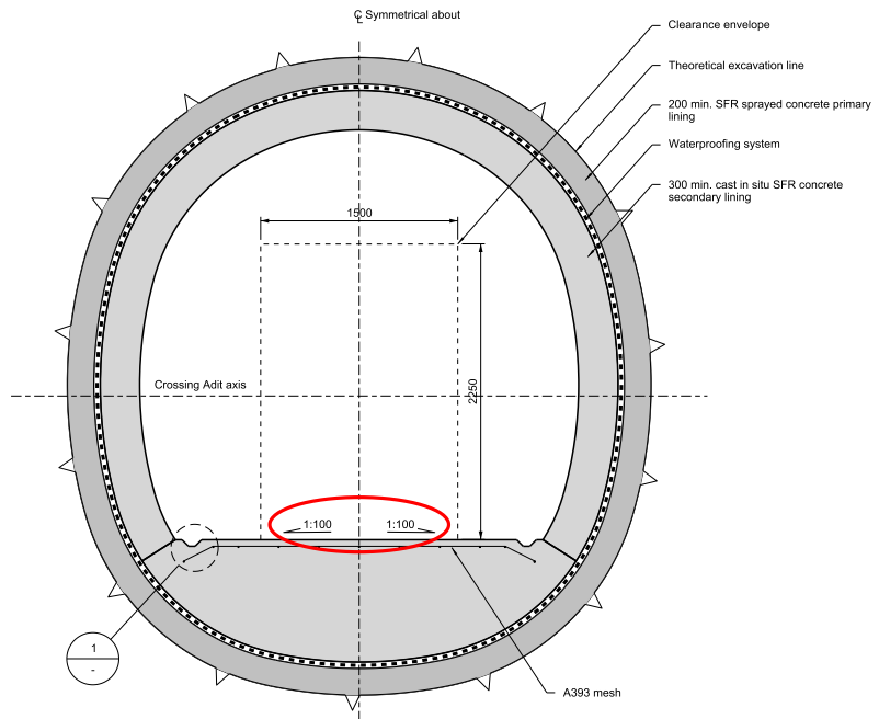
One of the design requirements from the drainage team was to provide 1:100 transverse slopes across the invert slab of shaft adits to drain any surface water into the side channels. Including this feature in the model would not add any additional value to the model, instead it would increase the complexity of the 3D model. The modeller would spend many hours on feature modelling at the T junction between the crossing adit and connection adit where two invert slabs with the same feature intersected. In the end it was decided that invert slab was modelled as flat, not including the slope feature. A note was added to the cross section drawing to highlight the 1:100 fall design requirement as shown in Figure 11.
Digital delivery of the design information
As a part of BIM, ProjectWise was used as a Common Data Environment (CDE) to store and manage all models and drawings for the project. It was also used as a tool for configuration management and deliverable submission.
Each model and drawing were assigned to a unique reference number and added to the Task Information Delivery Plan (TIDP) and Master Information Delivery Plan (MIDP) by the project manager with the essential attributes information such as Seed file, Primary Asset and Sub Asset ID. A bespoke script was run to import the information from TIDP and MIDP and generate the placeholders on CDE. This ensured the proposed deliverables created on ProjectWise being consistent with the logs on TIDP and MIDP. It also eliminated the risk of creating redundancy and losing control of the CDE.
Document workflow is an essential part of BIM. Drawings and models were submitted to the contractor and HS2 through ProjectWise following an established workflow.
The workflow for this project was based on requirements presented in BS 1192:2007+A2:2016 [1] ‘Collaborative production of architectural, engineering and construction information – Code of practice’. It helped with management, distribution and quality of design information. Every placeholder embedded property called ‘state’ and can be approved by person with appropriate authority to move it to next ‘state’. First state was always ‘Work in Progress’ and it was used to produce the design work. After the work was done a placeholder was approved by the originator which triggered an automatic background process called CAD-QA to ensure the placeholder was compliant with project standard and when successful, the placeholder was moved to state ‘Checking’. At this state the next person in the design process was responsible to check the design. Successfully approved the placeholder then moved to the state ‘Package Shared’, where it became visible to other disciplines in the design. This ensured that only checked design was shared with others and this was performed on a weekly basis. Next State for Placeholder was ‘Reviewed’ and only persons with ‘Reviewer’ authority were able to approve the ‘Package Shared’ placeholder. The last state of the process was either ‘Team Shared’ or ‘Client Shared’. ‘Team Shared’ was used for those submissions which were only submitted to the Contractor while ‘Client Shared’ included the submission to HS2.
The workflow process included built in automatic procedures. In the ‘Package Shared’ state incorporated an automatic i-model creation of 3D models, and in the ‘Approved for Team Shared/Client Shared’ state PDF renditions of the drawings were automatically created.
Conclusion
The designer hopes to set an example of using a project wide BIM system and 3D models to digitally deliver a large infrastructure project such as HS2 and to establish a comprehensive database that can be used for the construction, operation and maintenance. Feedbacks have been reported to the system developer, which will help to adapt the Common Data Environment to suit more detailed and complicated project requirements in the future.
Pioneering the use of full-scale BIM with 3D approach for such a large scale and complex multidisciplinary project in the UK, there were many challenges throughout the different design stages which required collaboration between the developer and the designer. Many lessons were learnt, and the BIM system also evolved as the project progressed. It has been proven that a mature BIM system will increase design production efficiency, reduce the construction risks and project cost and add value to the project. The valuable experience from HS2 C1 package will further the maturity of the current BIM system and benefit future projects.
References
- BS 1192:2007+A2:2016 – ‘Collaborative production of architectural, engineering and construction information – Code of practice’
Peer review
- Alex HulstonCAD Specification Manager, HS2 Ltd
- Andy KendallSenior Tunnel Engineer, HS2 Ltd