Railway drainage design in constrained environments. A case study in the vicinity of HS2 Birmingham Interchange Station
The HS2 Birmingham Interchange Station has been located to provide connections to multiple transport modes and routes. It is surrounded by major roads and situated close to Birmingham Airport and the existing Network Rail Birmingham International Station. Given its proximity to new and existing infrastructure, the design of the drainage for the catchment areas around and adjacent to the station presented a number of constraints. The way that the constraints have been overcome can be used to help to inform certain aspects of the design of future high-speed rail projects or multi-modal hubs.
The constraints in this area are presented in detail. The most obvious constraints are spatial ones which have affected the positioning of the ponds. Other constraints have led to the adoption of an attenuation tank rather than a pond for Bickenhill Cutting. The presence of a wet cutting and the need to deal with a low point is also examined. The existing topography has led to other design decisions. The use of six tracks in the vicinity of the Interchange Station required the development of a new functional cross section and drainage solution. The diversion of Hollywell Brook had its own spatial restrictions since it had to remain within the limits of land to be acquired or used. Also, within the area there is a need to integrate the HS2 drainage design with the Early Works Contractor’s design of new highway drainage.
- Written by
-
Julien Baron (BBV/Systra)

- Resource type
- Resource type: Technical Paper
- Intended audience
- Public Sector Clients
- Tags
- Drainage, Constraints, Station posts
Introduction
The authors are part of the production team responsible for the assets drainage design on the northern section of High Speed Two (HS2) Phase One – Lots N1 and N2 (Area North) of the Main Works Civils Contract (MWCC). Area North includes Long Itchington Wood Green Tunnel to Delta Junction and Birmingham Spur and the Delta Junction to the West Coast Main Line (WCML) tie-in. The main civil works in Area North are delivered by the BBV (Balfour Beaty Vinci Joint Venture) Integrated Project Team (IPT). There are 8 Sub-Lots (SL) and the assets described in this paper are within SL Five South (SL5S).
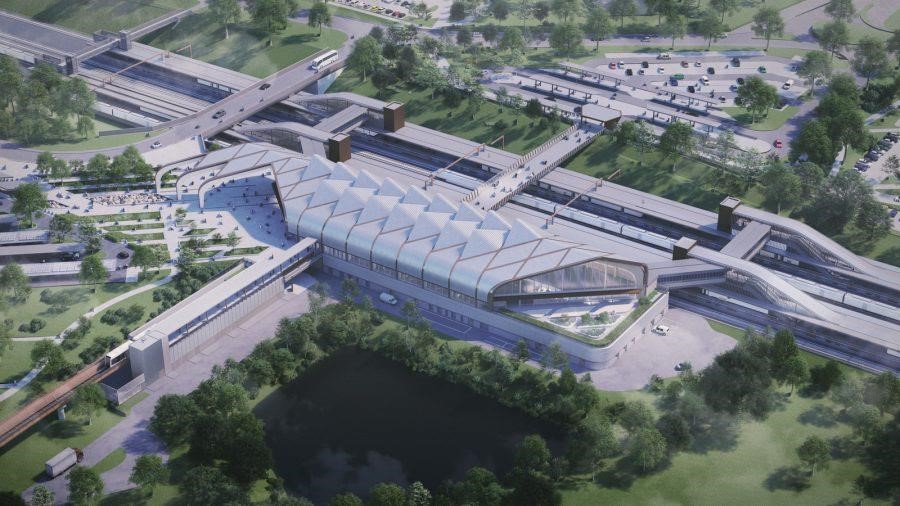
Good links into other modes of transport are vital in achieving the full environmental, social and economic benefits that high-speed rail can deliver. The HS2 Interchange Station in Solihull, as its name suggests, will do just that: it is surrounded by major roads and sits close to Birmingham Airport and Birmingham International Station.
With this necessary proximity to existing infrastructure comes the challenge of limited space and constrained geometry, and how to best fit everything into it. This applies to the civil structures themselves but presents an equal – if not greater – challenge when it comes to achieving the optimum drainage design.
In designing the drainage networks around the HS2 Birmingham Interchange Station, the team faced multiple constraints, many of which could be relevant to the design of drainage for future interchanges or multi-modal transport hubs. These include the location of attenuation structures, providing redundancy at low points in the track, the complexities of the station tracks themselves, diversion of existing water courses, and integration with other drainage networks.
This paper sets out the design of the drainage in Drainage Catchment 1566, in which the station sits, and in the neighbouring catchments of 1573 to the north and 1562 to the south. While attenuation ponds are HS2’s preferred solution, it was necessary to consider the alternative of an underground attenuation tank in Drainage Catchment 1573 to overcome potential hazards in construction and operation. This paper details how this alternative option was assessed and eventually selected.
In Drainage Catchment 1562 the proposed alignment of the track reaches a low point in the Diddington Cutting, which is a wet cutting. The specification calls for two drainage outfalls for such low points. The paper discusses what options were considered and selected.
In Drainage Catchment 1566, the design engineers created a series of new functional cross sections for the six-track station, transitions and crossovers. Another issue was how to design the sub-surface flow from the low point of the track formation. In this catchment there is also the diversion of Hollywell Brook and its position to deal with.
A remaining challenge, which is touched on finally in the paper, is how to best integrate drainage systems from HS2 and those from highway works designed by the Early Works Contractor.
Background
The HS2 Interchange Station is surrounded by major roads and situated close to Birmingham Airport and the existing Network Rail Birmingham International Station. The Interchange Station will be made up of two 415m-long island platforms, offering four platform faces, as well as two central high-speed through-lines for non-stopping services. The station will be linked to the National Exhibition Centre (NEC), Birmingham International Station and Birmingham Airport via an Automated People Mover (APM)[1] carrying up to 2,100 passengers per hour in each direction. In addition to the APM, the station will be fully integrated with other local buses, taxis and private vehicle options. It is situated between chainages 156+615 and 156+90 within Bickenhill Cutting and Bickenhill Embankment and in drainage catchment area 1566. See Figure 1.
Drainage Catchment 1566[3]
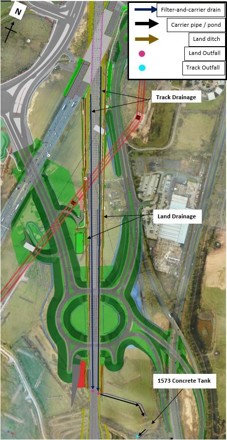
The Interchange Station sits within Bickenhill Cutting, which is classified as a wet cutting. Filter drains in the cess (the area outside the tracks at the edge of the trace) convey surface and sub-surface flows from the track earthworks, station platforms and footbridges and connect to another filter drainage network at Bickenhill Embankment. This system is then attenuated in a pond to discharge at for the mean annual flood (Qbar) to Hollywell Brook. There are two perimeter drains at the crest of the cutting to convey the overland flows between the station internal access road and the crest of the cutting to discharge to Packington Culvert. See Figure 2.
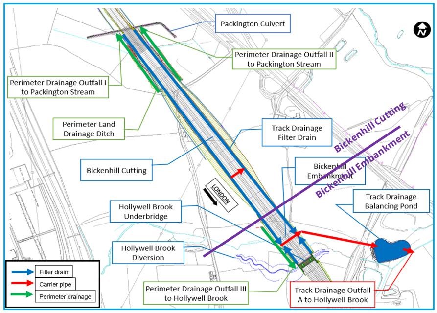
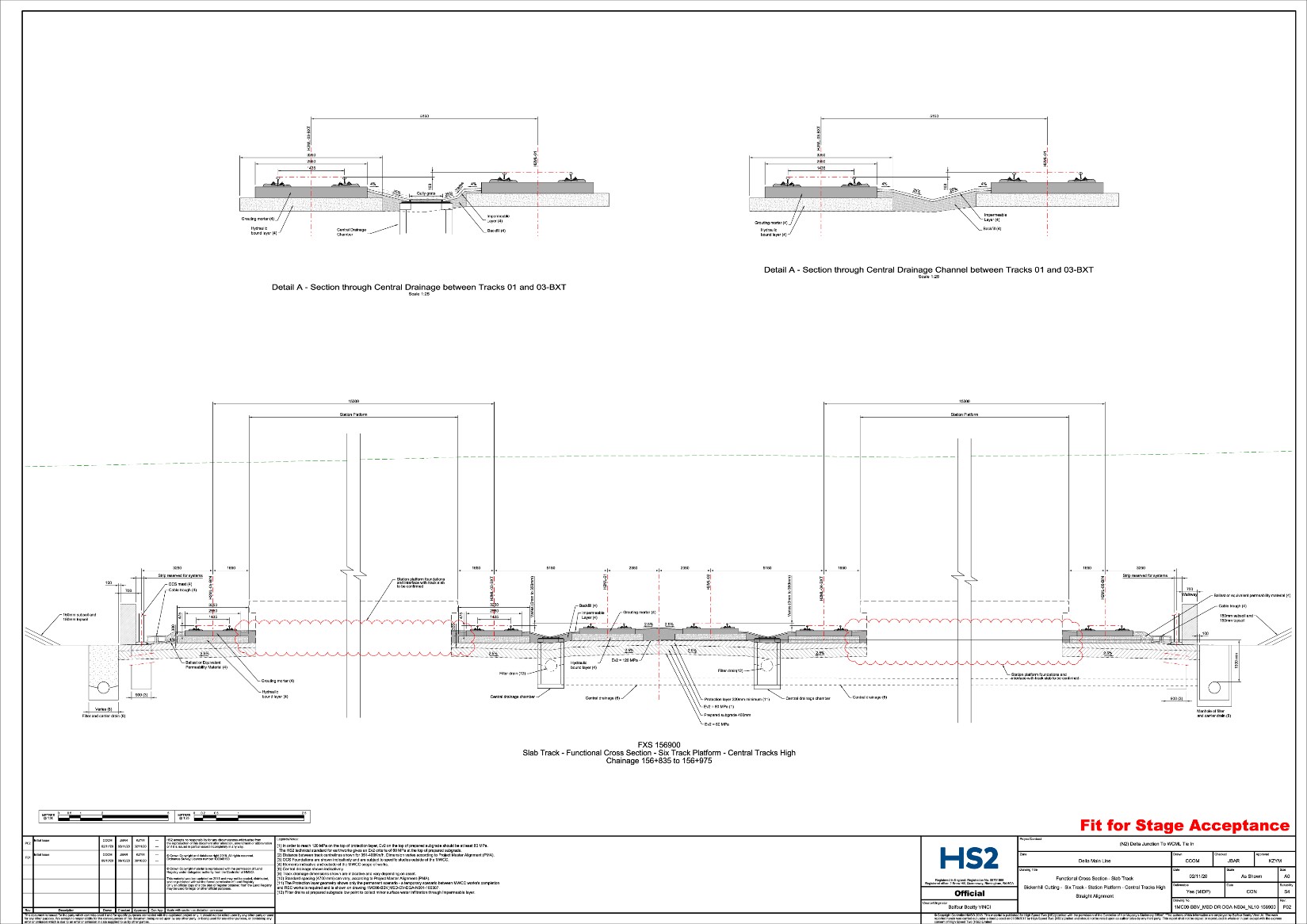
Figure 3 shows the functional cross section through the station. Slab track is used with concrete drainage channels between the central tracks. The run-off from the channels is conveyed under track crossings to the filter drains in the cess which also collect runoff from the outside tracks. Shallow filter drains in the central area drain sub surface flows in the track formation low points.
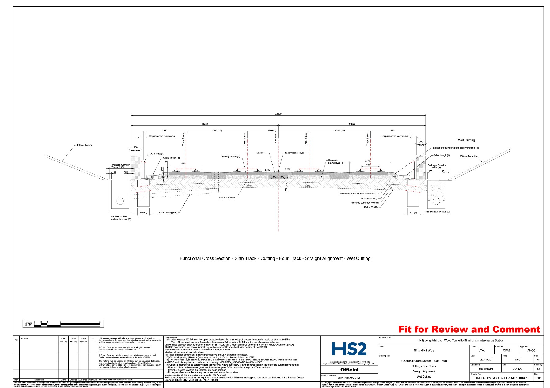
North of the station, the tracks are at the same level. There is a transition to four tracks either side of the station. See Figure 4 above.
Drainage Catchment 1573[3]
To the north of Drainage Catchment 1566 is Drainage Catchment 1573. This comprises the northern part of Bickenhill Cutting and Packington Embankment. Filter drains in the cess convey surface and sub-surface flows from the track earthworks. Filter drains rather than over-the-edge drainage were used on Packington Embankment due to spatial constraints with the close proximity of existing and proposed roads and the Birmingham Interchange station compound. The northern part of Bickenhill Cutting is dry but filter drains were provided at the scheme/consolidation design stage due to insufficient ground investigation (to determine ground water level) and a wet cutting was assumed. Detailed Design has remained the same as permitted by the Basis of Design document[2] (rather than change to a track-side ditch). This system is then attenuated in an attenuation tank to discharge at Qbar rate to Packington Watercourse. A combination of ditches and pipes along the east perimeter collects water from the external catchment and the embankment slopes and outfalls into Packington Culvert. A combination of ditches and drains along the west perimeter collects water from the external catchment and the embankment slopes and outfalls to an Early Works Contractor Highway Ditch on the northern side of the A452/A446 roundabout and to the Packington Culvert. See Figure 5.
Drainage Catchment 1562[3]
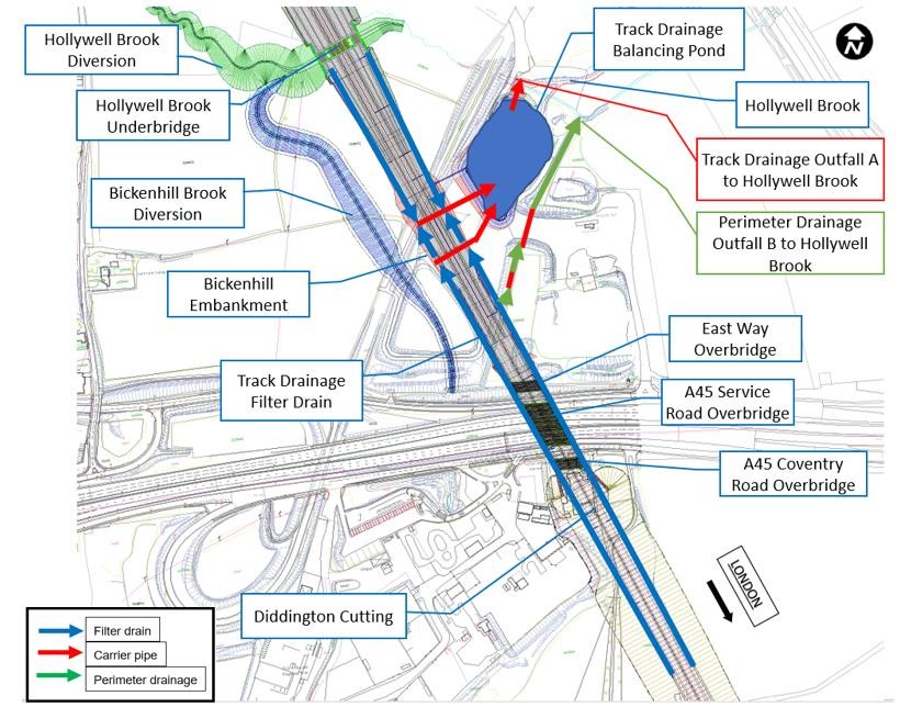
To the south of Drainage Catchment 1566 is Drainage Catchment 1562. The catchment comprises the southern part of Bickenhill Embankment and the northern part of Diddington Cutting which is classified as a wet cutting. There is 150m of shallow cutting within Bickenhill Embankment. Filter drains in the cess convey surface and sub-surface flows from the track earthworks. This system is then attenuated in a pond to discharge at Qbar rate to Hollywell Brook. The land drainage system comprises a combination of ditches and two culverts. A ditch for land drainage begins on the west side of the northern part of Diddington Cutting and flows north. The ditch is culverted under the A45 and then becomes Bickenhill Brook, which discharges to Hollywell Brook. There is a perimeter drainage system on the east side of Bickenhill Embankment which drains via ditches and culverts to Hollywell Brook. See Figure 6.
The 1573 Drainage Catchment Attenuation Tank [4]
The decision to use an attenuation tank for the 1573 Drainage Catchment was the outcome of a sift report looking at Packington Culvert and the 1573 Pond[4]. The sift report was reviewed against the following changes and constraints:
- Alignment (vertical) changes,
- Relocation of Interchange Station Platforms further North (about 72m),
- An environmental assessment,
- Engineering Director’s Communication (EDC) changes.
In parallel to the options for the watercourse realignment, the Design Joint Venture (DJV) (Mott MacDonald / Systra) were also asked to consider an option to provide the required storage volume for the associated track drainage network (Network 1573) via a buried attenuation tank, rather than an open balancing pond as per the majority of the networks across the entire route. This was driven by the observation that the earthworks interfaces between the A452 and associated A452/A446 roundabout, the watercourse and the Eastern Station Approach road would be very complex and introduce construction and operation hazards which could potentially be designed away via the use of the buried tank.
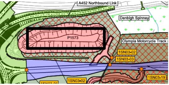
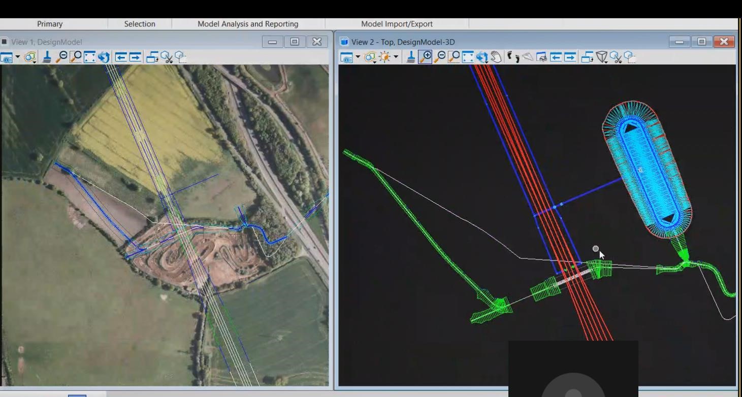
Figure 7 below shows the outline of the attenuation tank superimposed over the balancing pond.
To assess the relative merits of the two options, the pond and tank sizing would need to be carried out to the consolidation parameters introduced by the various EDCs, Technical Standards (TS) Baseline 15 (the Technical Standards that apply to Railway Drainage e.g. Railway Drainage HS2-HS2-DR-STD-000-000003 Rev P04) and updated climate change parameters. These needed to be implemented with the following key constraints:
- Groundwater levels in the area are reported to be very high in the supplied ground investigation data, peaking at almost existing ground level. Given the proximity of the watercourse and the ‘wet woodland’ of Denbigh Spinney, this appears to be a sensible input to take into the design,
- The scheme design pond outfall level was just under 200mm below the invert of the watercourse at the tie-in point (which would be common to the existing and the realigned route). As a result, it was already recognised that some optimisation was required for either option to be viable. However, to avoid making this any more challenging, the invert of any buried tank was limited to the invert of the existing scheme design,
- The footprint of the tank needed to be set at least 1m away from the toe of any nearby embankments to prevent excessive localised loading on the tank causing uneven settlement.
- The groundwater level requires the tank option to have adequate weight to prevent flotation;
- Both the tank and the pond option would need to be provided with an impermeable liner to prevent groundwater ingress.
Balancing pond sizing
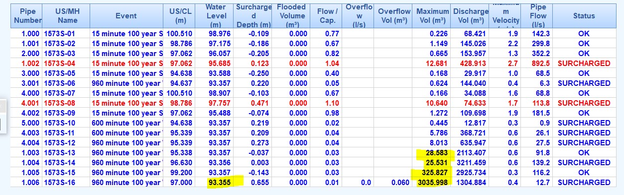
The attenuation for drainage catchment 1573 is required to control and convey peak flows for a 1 in 100-year flood event + 40% additional allowance for climate change. See figure 8 below:
The pond was assessed using the following base schematic plan of the system as shown in Figure 9:
The pond itself was judged to receive direct rainfall contribution over an area of 7000m2 (i.e., rain which falls straight into the base of the pond or runs in overland via the surrounding slopes). The initial sizing of the balancing pond yielded the following outputs and constraints:
Pond base level = 91.500m AOD (metres above ordinance datum)
Pond base area = 1000m²
Pond crest area = 5000m² based at 1:4 continuous slope. This was the design area, which would increase further once the pond crest was tied into the existing ground.
Height of water at maximum storage = 93.355m AOD
The volume of excavation required for the pond, using the existing terrain data available at the time of the sift report[4], was estimated to be 15,000m³ of material, all of which could be utilised elsewhere on the site if this was beneficial to the Main Works Civil Contractor (MWCC)’s mass haul strategy. This was based on an assumed side slope of 1 in 4 which is typical across the project as it provides a slope shallow enough to permit safe access and maintenance.
The base level of the pond would need to be raised to approximately 91.750m to achieve a gravity tie-in to the realigned watercourse – this was assessed as feasible and, should this option have been taken forward, the inverts would be adjusted to suit. At detailed design the area of the base and invert level may have needed a minor refinement to account for any base lining and ballast needed to resist uplift.
Attenuation tank sizing
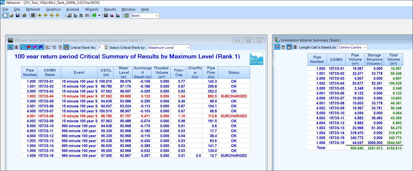
The initial sizing of the attenuation tank yielded the following outputs (volumes to nearest 5m3):
Outer Dimensions of Tank = 40 x 50m (2m deep) = 2000m2 footprint area.
Tank invert level = 91.500m AOD
Total tank internal capacity = 4000m3 See Figure 10 below.
This was shown to be adequate to store the required 1440-minute winter storm volume with some surcharged pipework within the network, but within acceptable parameters as laid out within the Technical Standard for track drainage.
The tank was required to be buried at a minimum of 3.15m below the existing ground level (assessed at an average elevation of 97.000 AOD) in order to provide adequate counterweight against buoyancy effects. Given the existing ground levels, it was possible to provide this and still maintain a gravity-driven outfall to the watercourse and, as such, the attenuation tank option was feasible. As with the pond option, the base level of the tank would need to be raised to approximately 91.750m to achieve a gravity tie-in to the realigned watercourse – this was assessed as feasible and if this option were taken forward the invert levels would be adjusted to suit. The volume of excavation required to install this tank was assumed to be approximately 12,000m3, assuming 1:2 side slopes to remove the need for temporary shoring.
This represented a 20% saving on total excavation volume compared to the pond. Approximately 8,000m3 of this material would be replaced on top of the tank, such that the yield for mass-haul purposes and use elsewhere on the site was reduced to approximately 4,000m3.
Aggregated Options to be considered in Sift Report
After considering a variety of initial options to be taken forward for formal Sift Assessment, two main choices were selected for consideration against the baseline:
- Option 1 – Realignment of the Packington Watercourse diversion with a circa 200mlong culvert, but maintaining the excavated balancing pond for storage of trace runoff from catchment 1573, or
- Option 2 – Realign the diversion as above, but use a buried attenuation tank for catchment 1573.
Having considered the initial studies outlined above, any option which maintained the baseline watercourse geometry was deemed to be evidently less beneficial to the project, as it would by default introduce a need to pump the flow within the watercourse at some point to maintain a hydraulic gradient. Hence both options were to be scored against the baseline design including the realignment of the watercourse.
Conclusions of Sift Report
Based on the assessment of the engineering, construction and environmental impacts and scoring within the sift report, it was recommended that Option 2 – to divert Packington Brook via a longer buried culvert which avoided the contaminated land and replace the balancing pond for catchment 1573 with a buried attenuation tank – be progressed. The critical drivers for this recommendation were as follows:
- Following the lowering of the alignment in this area, principally to provide major constructability benefits at the A45 and associated service roads, maintaining the baseline watercourse route beneath the trace would require mechanical pumping. The alternative diversion removed this need for pumping and can drain via gravity,
- Costs are reduced by moving culvert excavation out of contaminated land,
- There is a reduced health and safety risk by moving the culvert excavation out of contaminated land, and also by removing the need to install ballast via rocks/concrete blocks at the base of the large pond excavation,
- Option 2 reduces risks of long-term instability of very high slopes where the pond sits directly adjacent to highway embankments, which would have been difficult to inspect,
- Operation and maintenance processes are slightly simplified through the introduction of ‘hard engineered’ access to all features,
- Option 2 provides additional useable space for future landowner or tenants which is accessible from the Eastern end of the stopped-up Middle Bickenhill Lane,
- There is a much-improved opportunity to provide better visual amenity and potential for public use of the landscaped areas in future,
- Discouraging foraging mammals to leave their habitats at Pool Wood and Hollywell Brook is beneficial as it reduces the risks to said species of crossing other roads or car parks,
Detailed Design
The detailed design of the 1573 drainage catchment has resulted in an attenuation tank with a required storage volume of 2728 m³. The proposed tank is approximately 37m min length and width, with a height of 2.5m. The cover to the tank varies between 0.8m and 3.5m approximately. It is thought the tank will be of reinforced concrete construction using precast panels and subdivided into a number of bays. This form of tank will be easy to maintain because of the very good access, whereas a geocellular tank is difficult to maintain.
Diddington Cutting: low point treatment for potential blockage of primary drainage
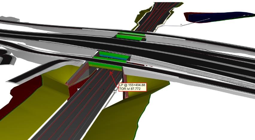
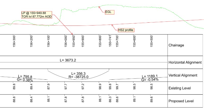
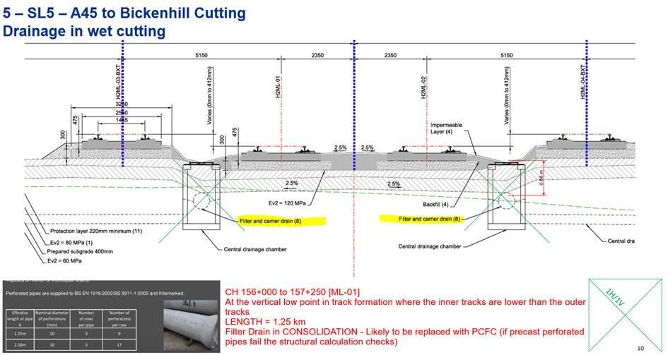
The proposed track alignment for HS2 includes a low point at Diddington Cutting (which is a wet cutting i.e. the base of the cutting is below the ground water level) at project chainage 155+950, below the proposed A45 Main Road Overbridge (see figures 11-1 and 11-2). In addition, levels of the central tracks at this location are higher than those of the outer ones; there are four tracks at this area.
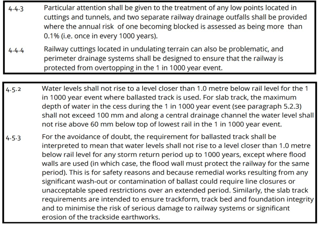
Clause 4.4.3 of HS2 Technical Standard Railway Drainage (TS RW-DR) (see figure 12) specifies that two separate railway drainage outfalls shall be provided where a low point is located within a tunnel or cutting. For the case under consideration, failure of an alternative drainage route due to blockage would approximately impact a length of railway network of about 200m either side of the low point (see figure 13).
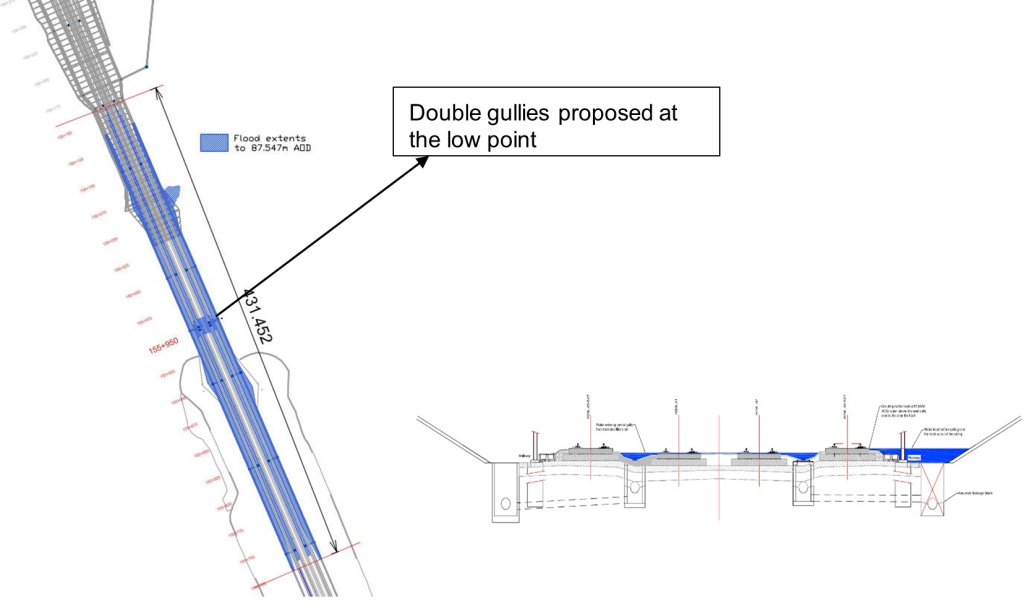
To comply with these requirements and remove the risk of flooding, the DJV design proposal incorporates two central gullies, so that the central channel drainage can be conveyed by one chamber via a separate central under-track crossing chamber (UTX) in the event the other blocks. The gully grating efficiency has a maintenance factor of 0.7, which has been selected based on the sag point and accounts for leaf falls and sediment runoff.
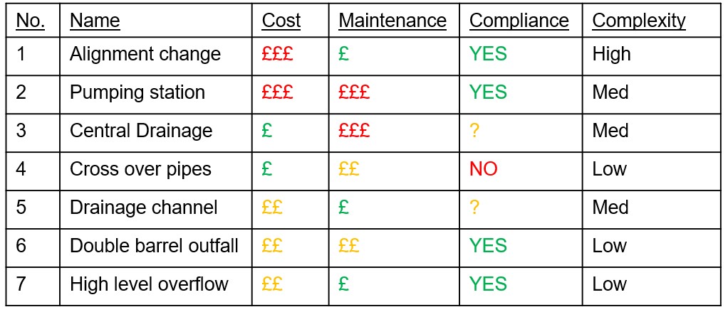
As shown in Table 1, a number of design options for this drainage system, which discharges into pond 1562, have been discussed with HS2 and aspects such as compliance, complexity, cost and maintenance considered for each alternative. HS2 and the DJV drainage team agreed that the proposal would deviate from the standard requirement on the basis of a hydraulic summary on 25%, 50% and 75% blockage of the primary filter drain system serving the tracks. The outfall size is 750mm diameter. The assessment, which is summarised in Table 2, concluded that there is 0.1% risk that the depth of water in the cess raises up to 200mm for a length of track of approximately 50m either side of the low point with a 75% blockage of the system.
* Not on HS2
** Top of protection layer on the track edge
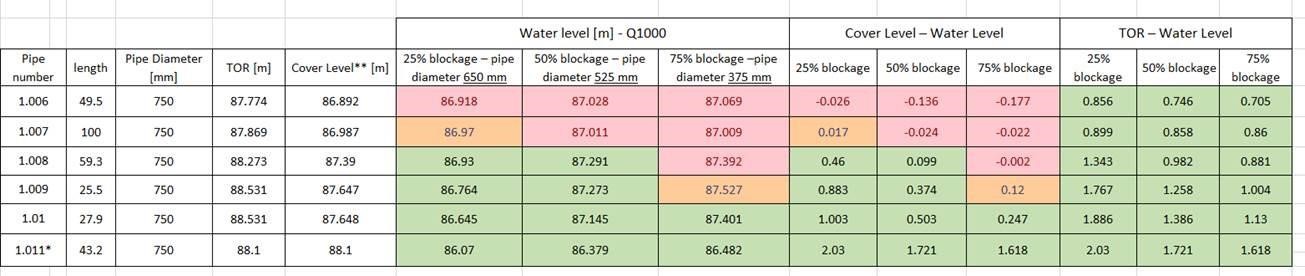
Given that HS2 maintenance activities will be undertaken regularly, and installation of suitable instrumentation would enable the levels of sediments at the catch pits to be reduced, it was subsequently agreed that a blockage of up to 50% is considered as the safest design.
In consistency with the project, catchpits with a minimum sump of 300mm have been implemented.
On the basis of the blockage assessments undertaken to date and the conversations held with HS2, changes to the following clauses(as outlined in figure 13) of the HS2 TS Railway Drainage have been/will be requested to permit :
- a) Clause 4.4.3: Single barrel arrangement shall be adopted for detailed design as the increase of water level in the event of blockage up to 50% is only marginal (23mm),
- b) Clause 4.5.2: Double gullies and gully leads provided at the low point would always have a 50mm freeboard from the central channel and therefore not pose a risk to the operations of HS2.
Six-Tracks at HS2 Birmingham Interchange Station
There were no standard functional cross-sections for a six-track arrangement as required at Birmingham Interchange Station, being a unique area on the project, so some were developed. There is a transition either side to four tracks.
Figure 3 shows the functional cross section through the station with central tracks high. The two outer tracks drain to the filter drains in the cess either side of the trace. The four inner tracks drain to two channels which connect to the filter drain on the eastern side.
There is also a functional cross section with the central tracks low.
Additional functional cross sections cover the station approaches northbound and southbound and the transitions and crossovers.
There is a specific drainage challenge of draining the sub-surface flow from the low transversal point in the track formation. About 1.25km length of the track formation between A45 to Bickenhill Cutting is designed with the inner tracks lower than the outer tracks. Figure 14 below illustrates a typical cross section which shows that the track formation is designed to have a low point between the tracks warranting the need for formal drainage in the form of perforated filter pipes/channels. As this drainage entity will be under the influence of the track loading zone, there will be a need for bespoke reinforced concrete products as the standard precast products cannot provide the adequate crushing strength. Final solutions are being investigated.
Diversion of Hollywell Brook
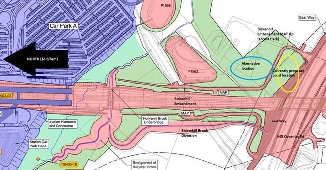
The diversion of Hollywell Brook had its own spatial restrictions to remain within the limits of land to be acquired or used. The Hollywell Brook is being diverted because of the location of the HS2 Birmingham Interchange Station.
Its revised location has been restricted to the location of the Hollywell Brook Underbridge (see Figure 15). This allows the flows from the Hollywell Brook to pass below the HS2 trace. The footprint of the watercourse is based on a low flow channel with side slopes of 1 in 2 and 1 in 6 side slopes tying to the ground to simulate the existing brook cross section as agreed with the Environment Agency. The Bickenhill Brook tie into Hollywell Brook is required to be tangential to the Hollywell Brook watercourse flow, to reduce the risk of the overtopping of water and reduce general flood risk. Another limitation is the presence of the Maintenance Access Track to the east of the Bickenhill Brook. As a result, the watercourse cannot be realigned elsewhere.
Integration of the HS2 drainage design with the Early Works Contractor’s design of new highway drainage
Numerous highways works in the vicinity of Birmingham Interchange Station have been designed by the Early Works Contractor (EWC). The area of work which affects the area of HS2 which is the subject of this paper is known as the Area B Early Works, specifically the A446/A452 roundabout which passes over HS2 within the Bickenhill Cutting part of drainage catchment 1573.It has been proposed to integrate the EWC highway drainage design (where possible) with the HS2 Railway drainage design in order to avoid duplication of drainage systems.
The part of the railway drainage system which is affected is the perimeter drainage system at the crest of the cutting slopes. Figures 16 and figure 5 show the highway drainage arrangement at the A446/A452 roundabout.
The HS2 Drainage and EWC Drainage ‘MicroDrainage’ calculation models[6] have been combined in order to model the effect of connecting the HS2 Drainage into the EWC Drainage. The southern part of the 1573 network discharges into the Packington Culvert. However, the northern part of the 1573 network connects to the EWC network, which eventually discharges in to two separate outfalls to the south at Packington Stream. Figure 16 shows the drainage system.
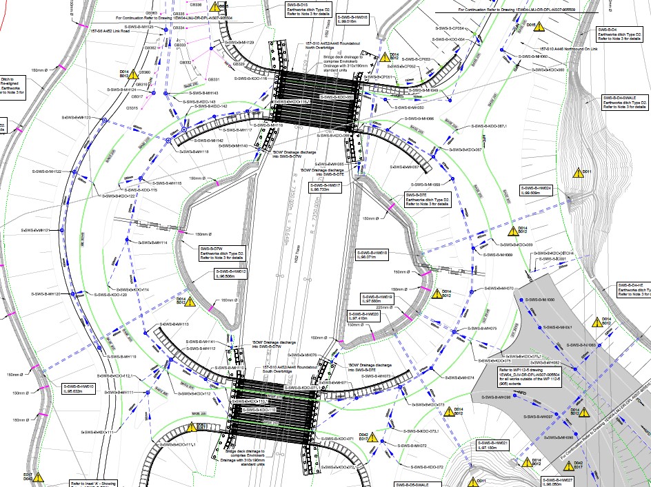
In a 1-in-1000-year event there is no flooding on the east side of the trace but some pipes flood on the west side. It has yet to be checked whether there is any danger of this flooding reaching the HS2 tracks. Should this be the case, flood protection measures such as bunds will need to be put in place.
Conclusion
Designing drainage networks for new high-speed rail interchange stations and structures presents a raft of challenges and constraints for engineers. These include a lack of space, impact on other structures during construction and operation, dealing with contaminated land, draining the station itself, diversion of existing water courses, and integration with other drainage networks.
In addressing these issues for the design of the drainage around the HS2 Interchange Station at Birmingham / Solihull, it was necessary to look at alternatives to the standard designs and specifications. This required collaboration between client, designer and constructor with consideration of long-term performance issues as well as constructability.
Specific lessons learnt that can be applied to other projects are:
- Sometimes an attenuation tank is a better option than a balancing pond. This very much depends on the proposed location, surrounding environment and topography.
- Providing dual outfalls at a low point can be an unnecessary expense. Analysis of the risk of blocking can lead to provision of a single outfall but double gullies.
- There is now a standard functional cross-sections set for the use of a six-track layout at stations.
- Realignment of watercourses needs to take into account many factors; topography, bridges, other structures and infrastructure.
- The need for close liaison between contractors working on the design of different aspects of a major project in order to ensure an integrated overall design.
Acknowledgments
The authors acknowledge the unwavering support provided by our DJV Drainage team colleagues in developing drainage solutions in this challenging environment, as well as BBV and HS2 for their collaborative approach.
References
- The slowest part of HS2 – The design of HS2 automated people mover – HS2 Learning Legacy
- DJV/BBV, HS2 (2016-2021). Basis Of Design (BOD) report – Drainage
- Calculation Reports for the 1562, 1566 and 1573 Drainage Catchments
- Sift Report for Packington Culvert and 1573 pond
- Specific Functional Cross Sections for BIS area
- EWC MicroDrainage models and layouts
Peer review
- Richard EngledowHS2 Ltd