Streamlining design coordination: connecting High Speed Two to the West Coast Mainline
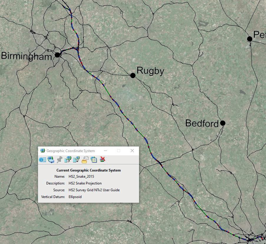
The High-Speed route joins the West Coast Main Line at Handsacre Junction just North of Lichfield, enabling HS2 Phase One services to continue North to Crewe and beyond.
All High Speed Two design and construction for assets such as civil structures, track and overhead power is undertaken within the same engineering coordinate system, called the HS2 Survey Grid. The West Coast Main Line is an Absolute Track Geometry route, and the asset information including rail alignment is maintained in the West Coast Grid.
The HS2 Survey Grid is well defined and understood, however the West Coast Grid is a legacy grid with no formal definition as defined purely by ground markers. To enable design coordination at the interface between High Speed Two and the West Coast Mainline, a workable transformation between the two systems is required.
This paper presents a new approach for transforming design between the two systems that uses the Transverse Mercator with Affine Postprocess (TMAF) projection, with the major benefit of building upon existing capabilities within design software such that data exchange is streamlined, and transformation risks are minimised with greater compatibility between complex design models and other data sources.
The derivation of the West Coast Grid TMAF, applicable to Handsacre Junction, results from a collaboration between High Speed Two and Network Rail. It is fully documented here including validation featuring ‘in situ’ survey control observations showing transformation accuracy to within ±4 mm.
The implementation of the TMAF process has clear impact on design coordination and advantages include the optimal coordination of the track alignment interface. It is expected to bring similar efficiencies at further points along the High Speed Two route.
The new approach is a significant step forward in coordinating interfaces with assets managed in legacy engineering grids and being fully generic is therefore applicable on other projects beyond rail.
- Written by
-
James Turner (HS2 Ltd/HS2 Ltd)

- Resource type
- Resource type: Technical Paper
- Intended audience
- Contractors
- Engineers
- Operators
- Tags
- engineering posts
- Interface posts
- Survey posts
- Track posts
Introduction
To ensure coordinated design across geographic, discipline and temporal interfaces, all High Speed 2 design and construction for assets such as civil structures, track and overhead power is undertaken within the same engineering coordinate system, called the HS2 Survey Grid.
The HS2 track alignment called Phase One HS2 Project Master Alignment baseline (PH1 PMA baseline) as an integral part of HS2’s Client Baseline. The principal component of the PH1 PMA baseline is the operational layout, this defined as a single contiguous alignment graphical/data model consisting of 87 track alignments within the HS2 Survey Grid. This graphical/data model consolidates the track alignment across all Contracts within the PH1 geographic boundary and provides a common linear design feature for the route across the different contracts designing and delivering the HS2 programme.
The West Coast Main Line is an Absolute Track Geometry (ATG) route, between 2004 – 2008 Network Rail delivered Trent Valley 4 tracking project to a co-ordinated design. Subsequently the track alignment geometry across all lines is maintained in the West Coast Grid (WCG), and as such subject to ATG principles that require modifications to the track design to be in West Coast Grid to maintain continuity.
The project requires a workable transformation in such a way that the alterations to the West Coast Mainline infrastructure works are seamlessly and accurately linked in with the respective High Speed Two (HS2) works in the Handsacre Junction area. The development of such a transformation at an early stage, using precise survey control observations, will reduce the risks in design and construction coordination.
The de-facto standard for such conversions is the use of multiple parameterised Helmert transforms[1]; however, these do not exploit full functionality of design platforms and can be awkward and error prone in use. Consequently, an alternate method is proposed and developed, which uses the Transverse Mercator with Affine Postprocess method[2], to define the West Coast Grid for Handsacre.
As secondary purposes, the resulting survey control network will be taken forward to the construction stage thus saving significant amount of repeat work, and the data collected will suffice to permit an assessment of the West Coast Grid quality for this area.
West Coast Grid
The West Coast Main Line is an Absolute Track Geometry (ATG) route and the rail alignment for Down Fast and Up Fast is maintained in West Coast Grid (London Euston to Colwich Junction). The current survey grid at Handsacre Junction is West Coast Grid with asset information data referenced and related to this coordinate system.
The West Coast Grid is a legacy grid installed between 1994-1998, and maintained ad-hoc until 2008, with no existent formal definition and hence relationship with further coordinate systems. The grid on the ground is purely realised by spigots in the gantries and retaining walls along the route and has not been checked for continuity to meet the modern spatial interoperability requirements for high speed and enhanced permissible speed (EPS) design.
HS2 Survey Grid
The HS2 track alignment is designed with reference to the HS2 Survey Grid in plan and the HS2 Vertical Reference Frame for height. The HS2 Survey Grid is a tailored Snake Projection[3] which has been designed specifically to minimise grid distortion at track level along the route and be continuous without zones or overlaps.
This HS2 engineering coordinate system is well defined with known direct relationships to other coordinate systems including OS Netv2009 ETRS89[4]. The HS2 primary control network forms the high order ground realisation of the grid.
Survey Control Observations
Survey observations to determine precise control coordinates for the West Coast ground markers within HS2 Survey Grid, and ETRS89 geodetic, were undertaken over a period of 3 months finishing May 2021. This included installation and observation of a new primary control baseline, two additional secondary control baselines and further 26 tertiary control markers. All work was undertaken to be compliant with the relevant Network Rail survey standard[5] and track access rules.
The aim of the work was twofold; to derive a rigorous transformation between the West Coast Grid and HS2 Survey Grid and to provide dimensional control for topographical data capture to inform design. A further secondary benefit of the work was to provide survey control suitable for the construction phase.
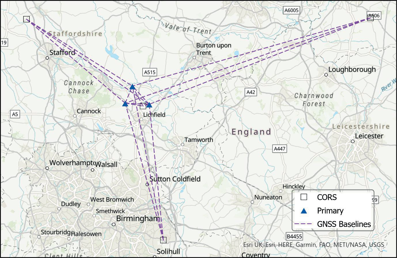
A two-day observation campaign, capturing high precision static Global Navigation Satellite System (GNSS) measurements, was employed to validate the primary control and determine new primary and secondary control coordinates. This comprised of a first session of long GNSS static observations, of minimum six hours for the primary markers and a minimum of 30 minute sessions for secondary markers. The second day of observations provided computational redundancy for processing the network by reoccupying all markers with different satellite constellation configuration. GNSS antennae were of geodetic type (choke-ring and flat-bed); these were utilised to record satellites observables with the elevation mask set to 15 degrees and 1 second capture frequency. A plot of primary and nearest Ordnance Survey Continuously Operating Reference Stations (CORS) locations is given in Figure 2.
The post-processing of the GNSS data was computed utilising an off the shelf survey software with additional checks performed on Geometric Dilution of Precision (GDOP) values, antennae heights, session length, cycle slips, satellite health status, atmospheric recorded behaviour as well as any other potential issues identified in the field books. Atmospheric corrections were excluded due to being partly modelled by the software and partly due to being removed by the double-difference method[6] employed due to the relative short distance to CORS. Five step post processing was followed to verify, validate, check observations, post-process the primaries, and subsequently post-process the secondaries based on the primaries solution via a least squares adjustment[6].
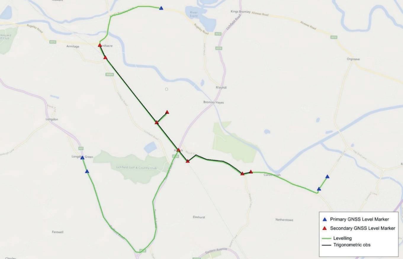
The high accuracy relative survey techniques of total station traversing and precise digital double run levelling[7] were used between the secondary baselines to determine the coordinates of the West Coast Grid ground markers, with a maximum distance residual of 2.6 mm.
Additional levelling checks were performed to link all primary markers and include these in the definition of the local plane to comply with the Network Rail survey standard. Post-processing the terrestrial observations was performed via a nine-step approach in the following order:
- Levelling – determining the local best fit vertical plane
- Levelling – calculation of the elevations for the main traverse
- Trigonometric – checking the integrity of the trigonometric observations
- Trigonometric – testing the unconstrained traverse
- Trigonometric – constraining the traverse
- Levelling & Trigonometric – calculation of HS2 grid coordinates for WCG markers
- Trigonometric – check the observations against supplied coordinates in WCG
- Levelling – fixing the WCG local plane
- Levelling & Trigonometric – updating the WCG coordinates and excluding the outliers.
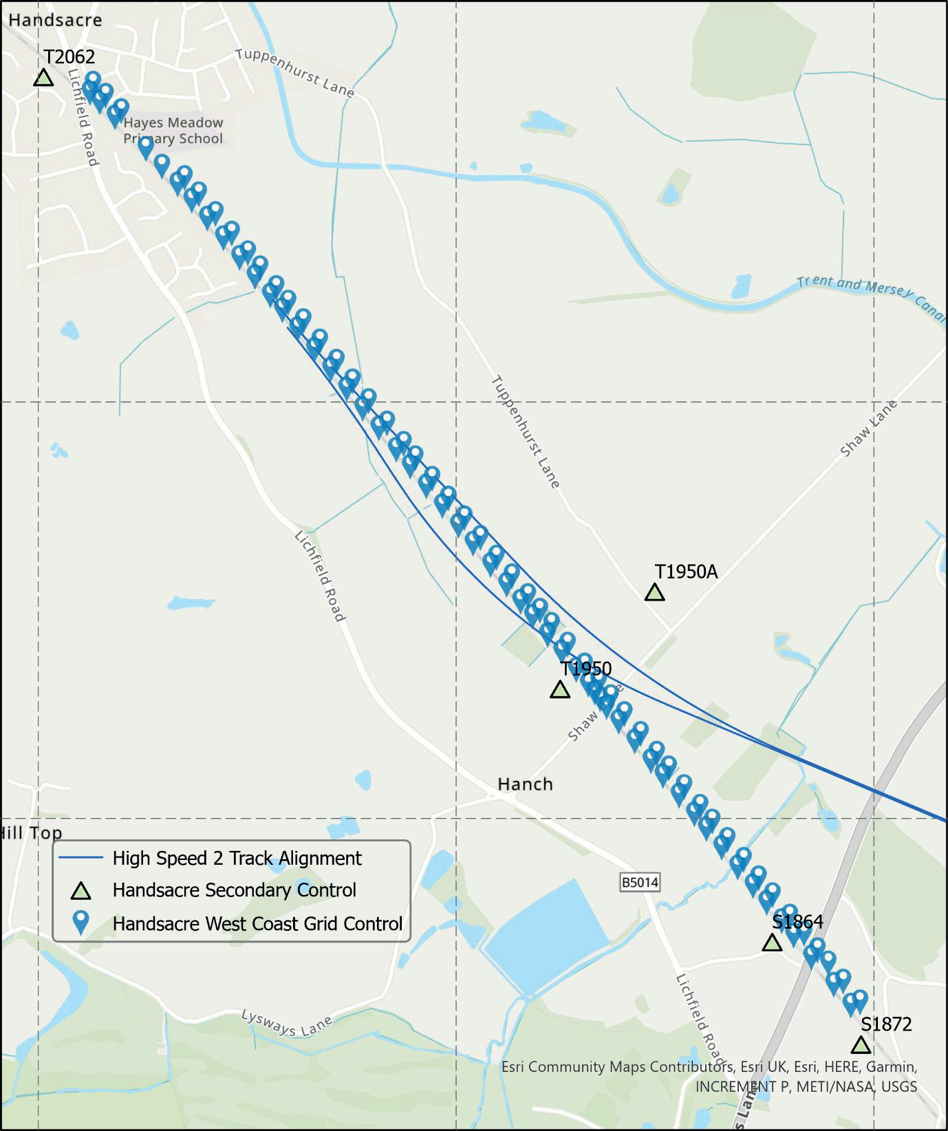
This resulted in a total of 101 control points which featured coordinates in West Coast Grid, HS2 Survey Grid, and ETRS89 geodetic (OS Netv2009). A plot of primary and secondary survey control locations is given in Figure 3, and the tertiary WCG control is given in Figure 4.
Grid Transformations
When at least one of the systems is undefined, the de facto standard method used for conversion of data between two projected grid systems is to derive and implement a mathematical Helmert transformation which comprises coordinate shift, rotation, and scale. While there is no contention that this method is invalid, there are a number of factors which make it unwieldy in everyday use. These include that multiple such transformations are required when there are more than two grids (for example – further transformations are needed for inverse methods; and further interfaces with spatial data in OS Grid), the process can be laborious and error prone particularly when manual entry of parameters is required, and design data cannot be tagged with a Geographic Coordinate system (GCS) thus a barrier to data identification and information use. This method is the benchmark for subsequent validation.
The Transverse Mercator is a cylindrical map projection which enables the curved surface of the Earth to be projected onto a flat plane. Other coordinate systems which use the Transverse Mercator include the Ordnance Survey National Grid[8].
The Transverse Mercator with Affine Postprocess (TMAF) is a sub-class of the Transverse Mercator which includes a final processing step that following the projection of the geodetic latitude/longitude onto the Transverse Mercator plane then an affine transformation is applied to the gridded coordinates. The advantage of the TMAF process is that it is present in the majority of design software; though it does require the parameters to be rigorously determined. Once defined however, this will enable a fully reversible coordinate system to be used repeatedly, as well as GCS tagging of design data, seamless conversions, no manual entry of parameters, and the implicit definition of relationships to all other project coordinate systems.
Derivation of the West Coast Grid at Handsacre
The aim of this process is to recreate the West Coast Grid at a local level and establish its relationship to other coordinate systems.
As a result of the control survey, the West Coast Grid ground control has been tied-in and observed so that each ground marker has coordinates in the HS2 Survey Grid; this means there is now a direct route to deriving respective geodetic coordinates for the WCG monuments using the HS2TN15 transformation.
Using the acquired set of control points, a process is now described to derive an optimal transformation to convert between grid and geodetic coordinates that has the benefit of being compatible with design platforms hence allowing more streamlined data transformations and interoperability.
From the above, we have one set of survey monument positions which feature coordinates in two systems:
{(𝜑, 𝜆)𝑛} ≡ {(𝐸, 𝑁)𝑛}(1)
Where,
φ is the geodetic latitude (ETRS89 OS Net v2009),
λ is the geodetic longitude (ETRS89 OS Net v2009),
E is the WCG Easting coordinate,
N is the WCG Northing coordinate,
n is the total number of control points.
The first step is to create an initial base Transverse Mercator projection which define a grid that is an approximate fit to the control:
Scale Reduction Factor = 1.000
Latitude of Origin = 𝜑̅
Longitude of Origin = 𝜆𝜆̅
False Easting = 𝐸
False Northing = 𝑁̅
Note that this assumes no geodetic coordinates cross the +180° meridian. The fit of the initial projection to the control coordinates is coarse with the magnitude of the differences at several metres (see pre-fit comparison statistics in Table 2).
The TMAF variation of the Transverse Mercator adds an affine transformation that, when used in software, is applied automatically following the Transverse Mercator projection[2]. The general form of the affine transformation is:
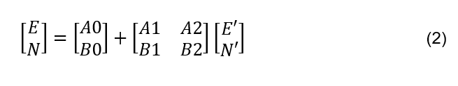
Where,
{(E,N)} is the set of survey control marker precise coordinates in the West Coast Grid,
and
{(E’,N’)} are the corresponding point coordinates which are derived by reprojection of the geodetic coordinates {(𝜑𝜑, 𝜆𝜆)} using the base Transverse Mercator projection. This general affine can be reduced to a similarity transformation by:
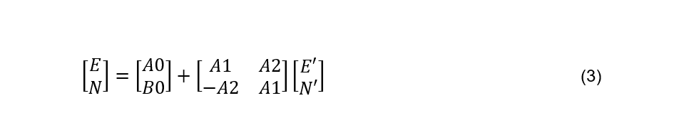
Which enables a scale, rotation, and offset to be applied to the coordinates. Consequently, given two set of grid coordinates, then the parameters A0, A1, A2 and B0 may be estimated using a least squares approach for optimal parameter values to minimise the transformation residuals:
Ax = 𝑏 (4) (4)
Where,
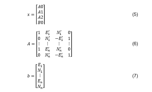
Thus, parameter values are derived by:
x= (𝐴𝑇𝐴)−1𝐴𝑇𝑏(8)
Results and validation
The resulting parameterisation of the TMAF defining the West Coast Grid at Handsacre Junction is given in Table 1.
| Parameter | Value |
|---|---|
|
Projection |
TMAF |
|
TM Scale Reduction |
1.000 |
|
TM Lat_0 (°) |
52.72891 |
|
TM Lon_0 (°) |
-1.85216 |
|
TM False Easting (m) |
159800.820 |
|
TM False Northing (m) |
242108.640 |
|
Unit |
Metre |
|
A0 |
-1991.6574212896 |
|
B0 |
1321.1075668335 |
|
A1 |
0.9999813828 |
|
A2 |
0.0082376952 |
|
B1 |
-0.0082376952 |
|
B2 |
0.9999813828 |
In total 101 surveyed ground marker control points were used within the estimation of the parameters; under a least squares estimation this may be confidently deemed a robust solution due to the high number of degrees of freedom. The post-fit residuals in Table 2 show no significant outliers from the resulting transformation, with RMS agreements of 4 mm and 3 mm respectively in Easting and Northing and maximum absolute deviation 14 mm.
| Pre-Fit | Post-Fit | |||
|---|---|---|---|---|
| Easting | Northing | Easting | Northing | |
|
Count |
101 |
101 |
101 |
101 |
|
Mean (m) |
-0.217 |
0.208 |
0.000 |
0.000 |
|
Std Dev. (m) |
5.252 |
4.277 |
0.004 |
0.003 |
|
Maximum (m) |
9.203 |
8.055 |
0.008 |
0.006 |
|
Minimum (m) |
-9.112 |
-7.061 |
-0.014 |
-0.010 |
In parallel, a Helmert transformation was derived to be the independent validation benchmark. This used the same ground marker control points, however with input as the sets of coordinates in West Coast Grid and HS2 Survey Grid ((𝐸, 𝑁)𝑊CG ; (𝐸, 𝑁)𝐻S2SG ). By definition, this enables conversions only from HS2 Survey Grid to West Coast Grid.
Comparison of the results from the two methods proved statistical equivalence: the RMS residuals for all control points in the HS2 grid then converted by both the HS2TN15+TMAF method and the Helmert method are identical to the nearest mm (±4 mm Easting; ±3 mm Northing).
Grid characteristics
The HS2 Survey Grid, as a contemporary defined grid, has known distortion characteristics with maximum 15.5 parts per million (PPM) along the route with RMS 3.9 PPM[9]. The West Coast Grid is a legacy grid featuring relatively unknown characteristics; this necessitated an assurance check on the fitness for purpose of the engineering grid by ensuring there is minimal variation between distances within the digital coordinate space and distances measured within the physical ground environment.
To check the grid a coarse digital terrain model (DTM) sourced from the Shuttle Radar Topography Mission[10] was used to generate ellipsoidal referenced ground points across the domain of interest. These values enabled the generation of a heat map showing the map projection distortion characteristics of the West Coast Grid TMAF projection for the area of interface with High Speed 2 (Figure 5). All distortion values were below 20 PPM (equivalent to 2 cm distortion per kilometre) thus the West Coast Grid at Handsacre is confirmed as a viable design and engineering coordinate space.
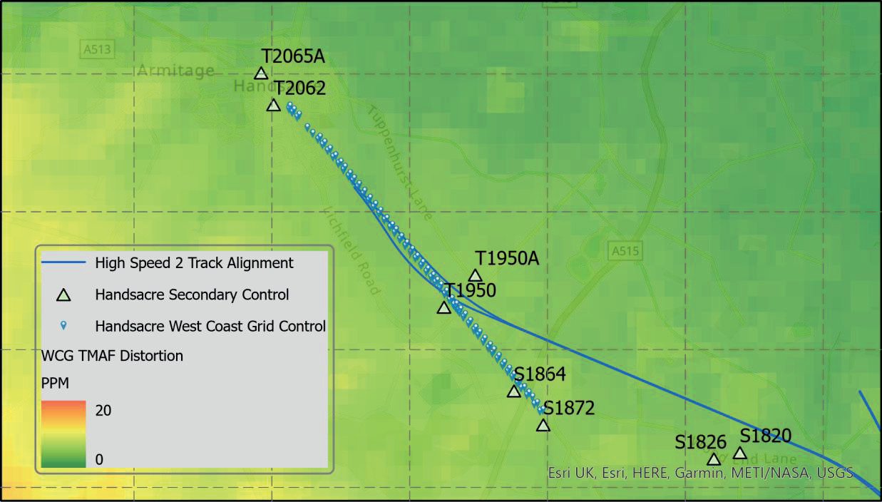
Units are parts per million distortion (PPM).
Irrespective of the method used, all the transformations derived as part of this work use the same input control points, covering the spatial area identified in Figure 4. Beyond these extents no warranty can be given on the validity of the West Coast Grid TMAF transformation as a method of reproducing West Coast Grid coordinates. The authors recommendation is to cease any use beyond 500 m from the outer control limits, or to acquire further ground control observations to quantify the level of deviation. However, as evidenced by the grid distortion analysis (Figure 5) it is seen that the wider coordinate grid defined by the WCG TMAF is of engineering quality therefore while there is no warranty on the reproduction of WCG coordinates outside the above bounds, the TMAF coordinate grid itself is fit for wider use (at minimum encompassing the further secondary control S1820 baseline and all tie-ins to the High Speed 2 alignment).
Vertical transformation
It should be noted that the parameters denoted only operate to attain planar grid coordinates and do not affect, or indeed achieve, heights above project datum. As part of the control survey works it was determined that there is a 69 mm difference in levels between West Coast Grid and HS2 Survey Grid which requires integration within transformation procedures to ensure alignment of data, such that:
Implementation
𝐻𝑊CG = 𝐻𝐻S2𝑉RF + 0.069 (9)
The West Coast Handsacre definition has been defined as a Geographic Coordinate System that can be used within design applications. This has enabled several benefits which have streamlined the coordination of asset and design data between the principal engineering coordinate systems. Benefits include:
- West Coast Handsacre definition file disseminated to users through Bentley managed workspace;
- fully reversible and compatible transformation procedures (in line with the UK Geospatial Strategy[11]);
- reducing conversion errors and increasing efficiency (including cessation of requirement to use further software for conversions);
- compatibility with web map services providing contextual background information for design;
- direct compatibility with data from third party sources such as Ordnance Survey mapping;
- assignation of the GCS made within the design data directly thus enabling direct data identification;
- seamless integration of design from multiple sources into the same coordinate space using ‘on the fly’ reprojection methodology;
- direct relationship now known between West Coast Grid and GNSS positioning;
- utilising the advanced capabilities of contemporary design software platforms when working on legacy coordinate grids.
Confidence in the reprojection of design data between the geographic coordinate systems is paramount to the design process. Two additional design models have been created to assist with the validation of reprojected design data, and these are detailed below. The two design models contain 9 control points that have been extracted from the survey produced by Bridgeway. The control points provide complete coverage over the extent of the design works at the Handsacre Junction:
- Model 1: Control points on HS2 Survey Grid;
- Model 2: Control points on West Coast Handsacre Grid;
- Model 1 is attached to design models that have the GCS set to HS2 Survey Grid prior to reprojecting to West Coast Handsacre Grid. Model 2 is then used to validate the reprojected Model 1.
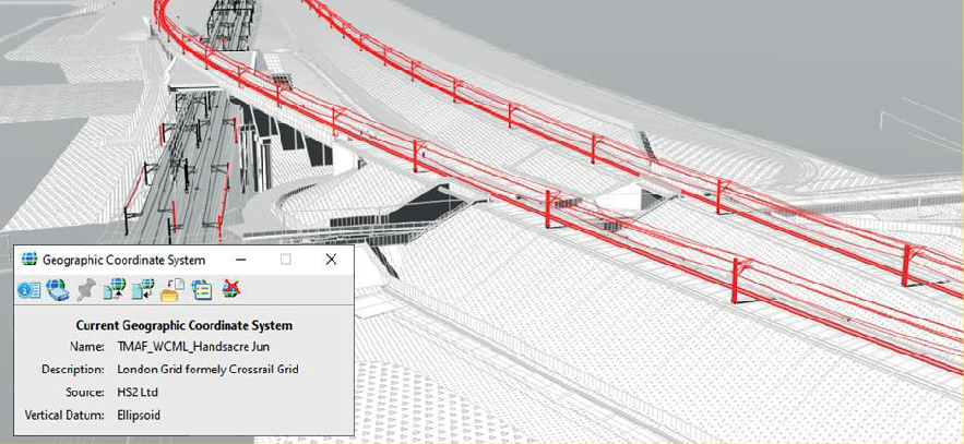
The federated model comprising input data from the two grids is shown in Figure 6.
Track Alignment Interface
Design Scope and Alignment Interface
HS2 remitted Network Rail through the On Network Works (ONW) contract to develop the Handsacre slow line connection, in parallel HS2’s Main Works Civils Contractor (MWCC) are remitted for the design of Railway Substructure elements – Civils embankments and structures.
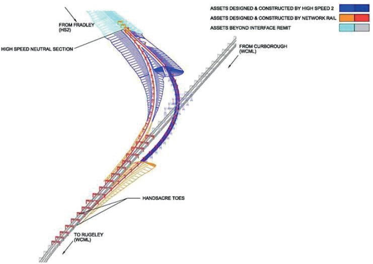
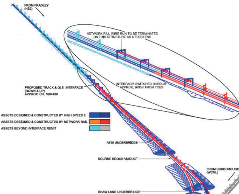
Figure 7 details the contractual delivery partition mechanism employed[12], thus highlighting the necessity for a robust and efficient transformation approach for design information between the two grid systems to enable track alignment developed by ONW to be used by the MWCC to define Railway substructure. Figure 8 identifies the location for the Track Alignment Interface point; the location was proposed due to being sited on a horizontal straight element of fixed gradient of 0.2% on an earthwork substructure.
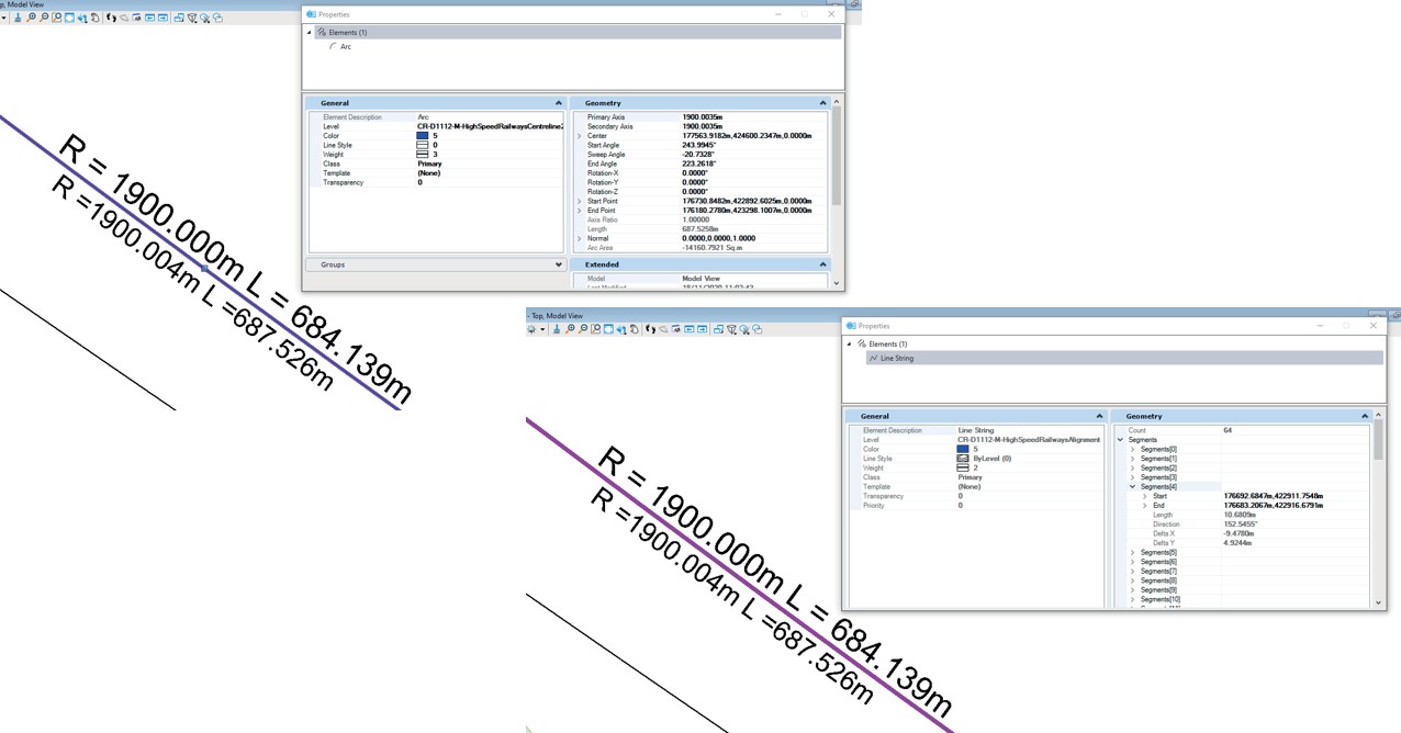
The process of translating curved track alignment geometry between survey grids does unavoidably fragment the true design geometry into a segmented line string as demonstrated in Figure 9, a geometric arc of radius 1900m originally designed in HS2 Survey Grid has been replicated in the NR WCG design, however using the TMAF method to reproject the WCG graphical model to HS2 Survey Grid this arc is approximated by a line string segmented into 64 linear chords losing its true geometric properties.
As linear straights are geometrical preserved when transformed between survey grids, selecting the interface point on a straight with fixed gradient mitigates the inaccuracy in defining a fixed point common to both alignment designs in their native grid systems. It is the recommendation where there is a need to design and deliver track work across different survey reference frames, project scope and contract boundaries are defined with consideration to the track geometry features to ensure there is a section of straight with constant gradient.
Alignment Interface Reference Chainage
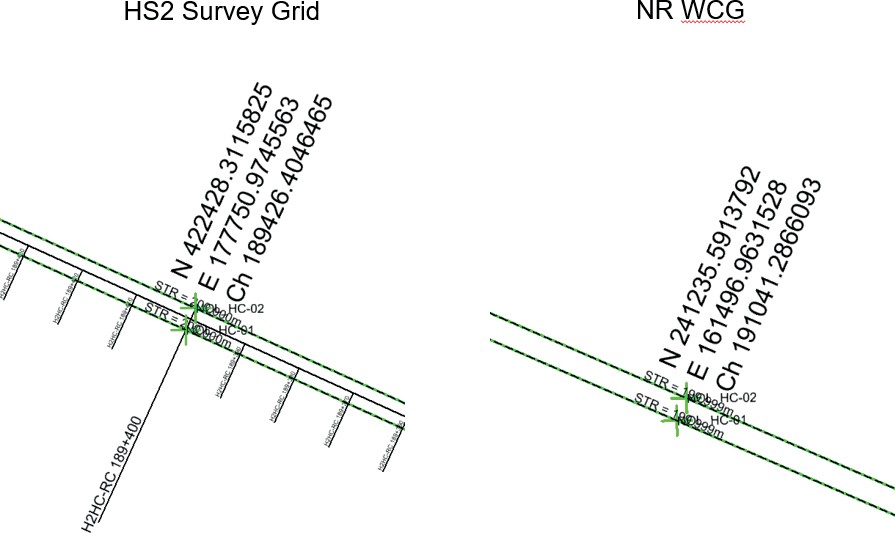
Both Network Rail (West Coast Mainline) and HS2 use an Absolute Reference Chainage (ARC) to provide fixed linear positioning of assets along the route. These are defined from independent datum points and follow their respective infrastructure corridors and as such do not feature commonality between the systems. In line with the Network Rail requirements the ONW contractor has used the WC ATG chainage to define the start stationing for the alignment model, therefore the proposed alignment interface location given within the Contract Requirement Document (based on the HS2 ARC at 189+400km) can also be referenced as a linear position on the H2HC-02 at 189+426km (HS2) and DES HS2 Up 191+041km (NR). For the management of the alignment interface that is used as common linear design feature across the different contracts, the use of a chainage description without qualification of the track baseline is insufficient as the same linear location can have multiple and valid chainage values (Figure 10).
Defining Alignment Interface Coordination Element
Although the use of chainage to describe the linear location of design boundaries is commonplace, due to the differences between datums and track baseline lengths there is a need to manage the interface in coordinate space. Furthermore the definition of a single point will only ensure commonality of the alignment design at that point. The engineered definition of the alignment interface between the designs within different survey reference frames critically needs to be defined as a coordination element to enable validation that section of track is on a common bearing and gradient.
The TMAF method builds upon existing capabilities within design software enabling the track designers at the ownership boundary to fix a common and overlapping vertical and horizontal element which fully defines the alignment interface.
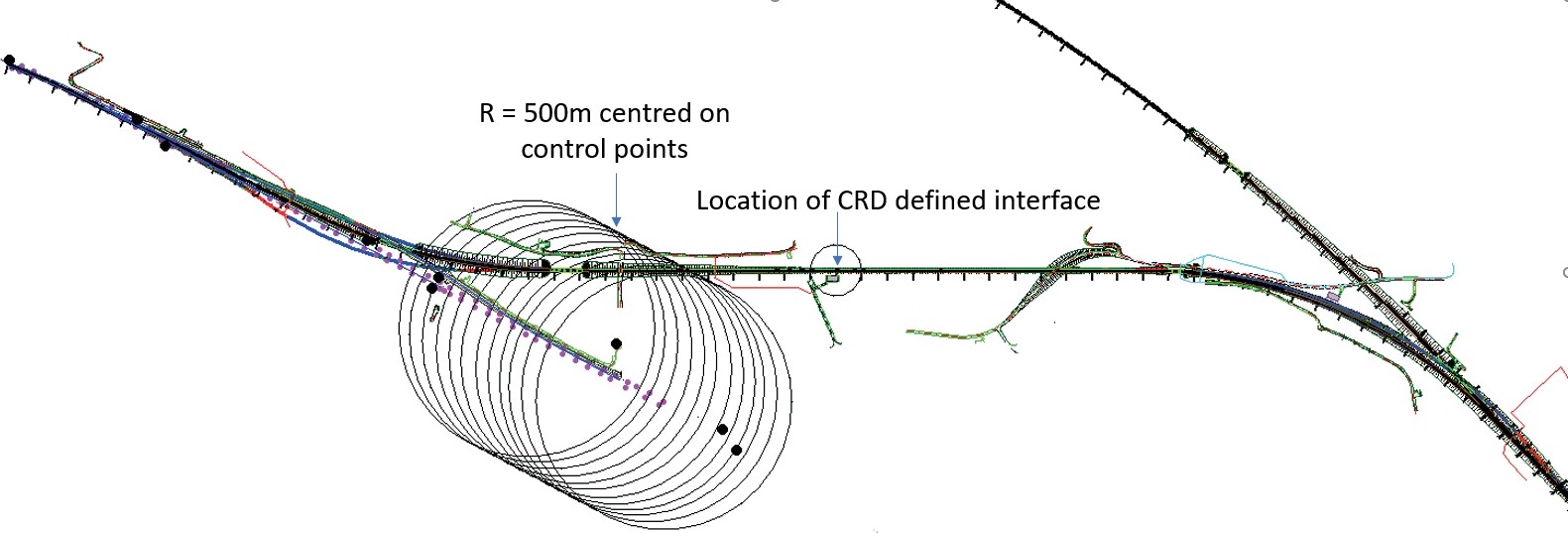
Although this paper recommends validity of the WCG TMAF only within 500m of the control points used in the computation of the transformation parameters, in Figure 11 it can be seen that the identified design interface point is beyond this boundary. However, the WCG TMAF heat map (Figure 5) demonstrates within this zone that the coordinate space remains of an engineering quality and can be used to define the alignment geometry in both survey reference frames.
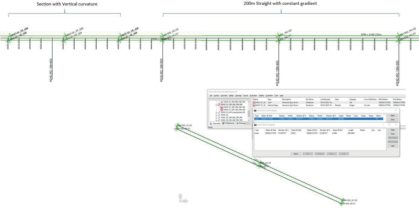
The definition of the alignment interface coordination element does not need to be the full extent of the current PH1-PMA design element that the design interface point is located upon. The principle is to establish an element that is adopted in both designs as a fixed end to the design. Therefore, it is preferable for the extents of this element not to coincide with actual design features.
A 200m section of straight with a 0.2% constant gradient was extracted from the PH1 PMA baseline as an exact copy and defined separately within the geographic/data model used by the track design software. This also retains separation between the section of the same straight horizontal element with vertical curvature which is within the Network Rail design boundary.
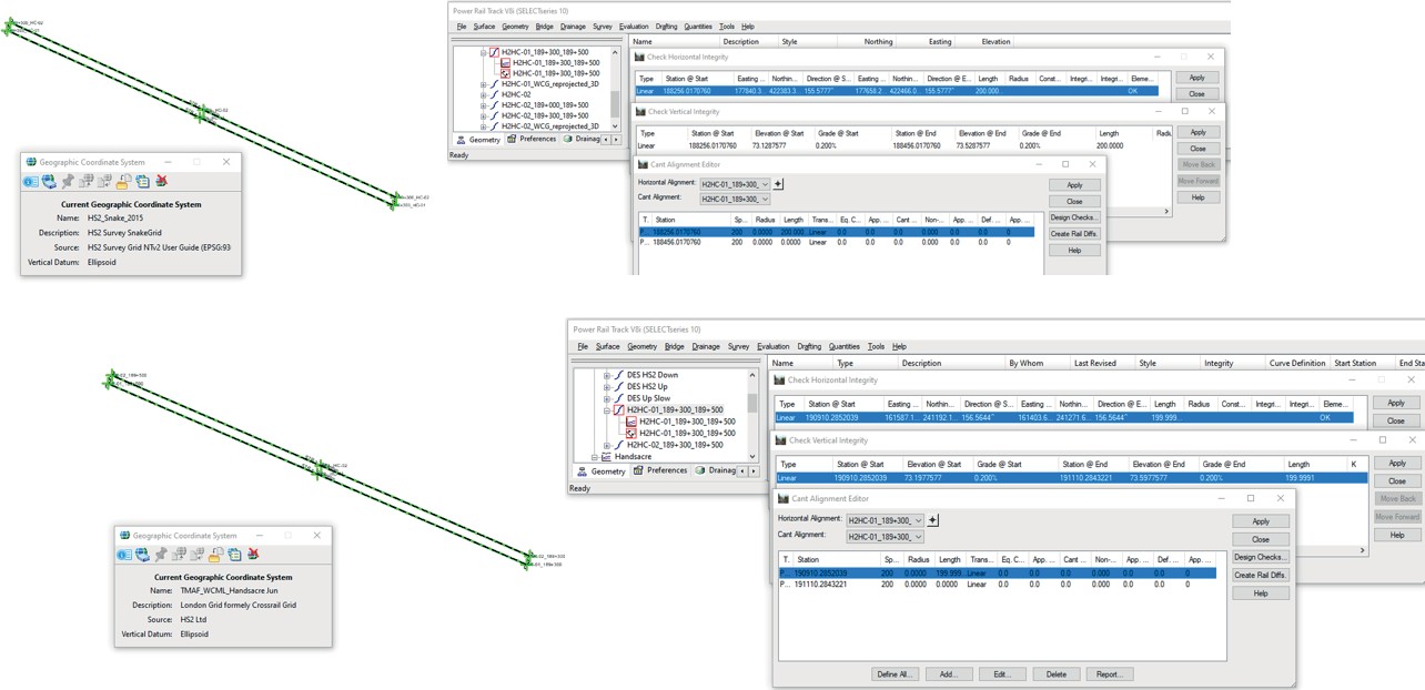
The track design software holds the geometry data within an XML data model, and is then graphically represented within Bentley Microstation permitting the CAD model to be tagged with the HS2_Snake_2015 (HS2 Survey Grid) geographical coordinate system.
Within the design software, the graphical representation (2D & 3D) of the coordination element tagged to HS2_Snake_2015 geographical coordinate system is referenced into a new CAD model tagged with the TMAF_WCML_Handsacre Jun geographic coordinate system. Also applying the vertical shift to the referenced model, this is then “merged to master” fully converting through the design model with transformed coordinate definition into the new CAD model.
Within the track design software then the WCG graphical model of the straight element is then used to generate the model in WCG as a track alignment with horizontal, vertical and cant components.
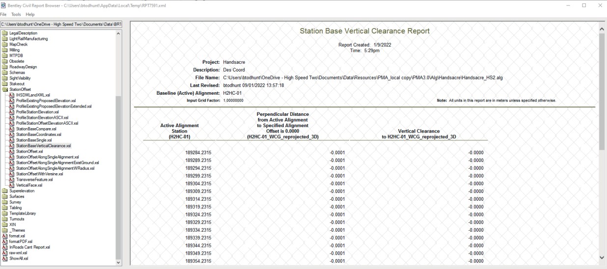
In order to validate the transformation, the process was reversed using the new coordinate geometry in WCG with 2D & 3D graphical output transformed back to HS2 Survey Grid. The vertical shift was removed before importing the transformed 3D horizontal and vertical geometry using the 3D track centreline in the track design software.
The report in Figure 14 shows the horizontal perpendicular offset and vertical differences between the PH1 PMA baseline alignment for H2HC-01 and the imported 3D track centreline geometry translated back from WCG. The results are within the positional tolerances used by the track design software to resolve continuity across elements (0.0005m) and accepted as the same design element definition.
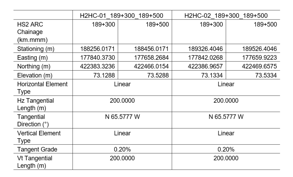
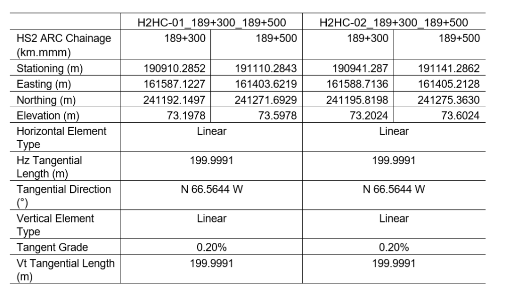
The design interface points are detailed in Table 3 and Table 4 for HS2 Survey Grid and West Coast Grid respectively. The use of a defined fixed design coordination element, represented in both HS2 (Table 5) and Network Rail (Table 6) design models, allow the independent development of the design beyond this element to occur without impacting onto the agreed track alignment interface. The PH1 PMA baseline can be trimmed to this element removing the NR Handsacre connection alignment to ensure information on track alignment is supplied via the design contractor responsible for delivery and a single and current version can be maintained.
Defined Alignment Interface Coordination Element
| H2HC RC | H2HC-01 | H2HC-02 | |
|---|---|---|---|
|
Chainage (km.mmm) |
189+400 | ||
|
Stationing (m) |
189384.2315 |
189426.4046 | |
|
Easting (m) |
177750.1473 |
177749.3207 |
177750.9746 |
|
Northing (m) |
422426.4898 |
422424.6695 |
422428.3116 |
|
Elevation (m) |
0.0000 |
73.3288 |
73.3334 |
| HS2 ARC | DES HS2 Down | DES HS2 Up | |
|---|---|---|---|
|
Chainage (km.mmm) |
189+400 | ||
|
Stationing (m) |
191010.2848 |
191041.2866 | |
|
Easting (m) |
161496.1674 |
161495.3723 |
161496.9632 |
|
Northing (m) |
241233.7556 |
241231.9213 |
241235.5914 |
|
Elevation (m) |
0 |
73.3978 |
73.4024 |
Conclusions
The TMAF method can be used as a flexible solution in a variety of scenarios where critical interfaces require millimetric levels of accuracy for transformation of design data between project grids. In particular, the principal application is for defining local or legacy grids within design software platforms. It enables more accurate and compatible transformation procedures for infrastructure design and examples have been given, in particular, for the optimal management of the track interface.
The accuracy of the TMAF process is commensurate with existing methods however it offers significant benefits in streamlining conversion procedures and reducing potential for errors and misidentification. The method is generic and therefore applicable both to the High Speed 2 project and further engineering projects which interface with existing infrastructure maintained in legacy engineering grids.
Acknowledgments
The authors acknowledge Bridgeway Consulting Limited for undertaking the ground control observation work and supporting the development of the transformation.
References
- Iliffe J.C. and Lott R (2008) Datums and Map Projections, ISBN 978-1-904445-47-0.
- Safe Software. TMAF: Transverse Mercator (Gauss/Kruger) with Affine Post Process. Online: (Access date 2021-12-10).
- Iliffe, J.C, Arthur J.V and Preston C (2007) The Snake Projection: A Customised Grid for Rail Projects, Survey Review, 39:304, 90-99.
- Turner J, Preston C, Winthrop R, Thatcher I, Swales P and Finney J (2021) Advances in engineering survey grid transformations for rail infrastructure. High Speed Two (HS2): Infrastructure Design and Construction (Volume 1). January 2021, 461-471
- Network Rail (2019) Topographic, Engineering, Land and measured building surveying – Strategy and General. NR/L2/TRK/3100.
- Blewitt, G. (1997) Basics of the GPS Technique: Observation Equations, Geodetic Applications of GPS, published by the Swedish Land Survey.
- Uren J. and Price B. (2010) Surveying for Engineers, ISBN 978-0-230-22157-4.
- Ordnance Survey (2020) A Guide to Coordinate Systems in Great Britain. Ordnance Survey, Southampton, UK.
- Iliffe, J.C. (2014) Snakegrid Report HS2P1+14. HS2-HS2-GL-REP-000-000003.
- USGS (2018) USGS EROS Archive – Digital Elevation – Shuttle Radar Topography Mission (SRTM) 1 Arc-Second Global. Online: (Access date 2022-01-07).
- Geospatial Commission (2020) The UK’s geospatial strategy 2020 to 2025. Online: (Access date 2022-01-07).
- Network Rail (2019) Client Requirements Document Handsacre Junction. 149850- NWR-REM-MAN-000001; IP 724 – NR/PSE/FRM/0239.
Peer review
- Jonathan RhindHS2 Ltd
- Rick Hartwig The Institution of Engineering and Technology (IET)