Reducing the impact of temporary works on third party assets
Costain Skanska joint venture (CSjv) were instructed to undertake the works at the St James Garden (SJG), where the team designed and erected a unique and fully encapsulated mobile scaffold structure to support the archaeological excavation and exhumation works within Area J of the cemetery. To comply with Schedule 20 of the 2017 High Speed Rail Act[1], CSjv proposed the structure, which would provide shelter, care, dignity and respect, while providing a safe, weatherproof environment for a team of 50 personnel.
System scaffold was used to develop a design incorporating a light-weight bridge panel system, and 130m long central spine beam with rolling tracks forming the eastern and western foundations for the 60m x 28m structure. Upon the completion of half of the Area J exhumation and archaeology works, an encapsulation structure with a surface area of over 3000m² was moved on tracks to the northern half of the cemetery using a tirfor winch within 90 minutes.
With the capacity to move the structure on above ground foundations, the interface with live subterranean services and the potential risks of loading out over a sensitive historic Thames Water asset were greatly reduced as were the risks associated with wind-load. All materials used were either returned to market or recycled and repurposed as site-won materials, making the structure 100% sustainable.
This paper provides an overview of how this project was achieved and how this innovative approach could be of use to other major projects dealing with this type of archaeological challenge.
- Written by
-
Ejaz Qayyum (Costain/CSjv)

- Resource type
- Resource type: Micro-report
- Intended audience
- Consultants
- Contractors
- Leadership Teams
Background and industry context
This paper is presented as part of the works to deliver the Enabling Works Contract (EWC) on the southern section of High Speed Two (HS2) phase one which includes demolition of buildings within the wider Euston area, utility diversions, environmental and ecological monitoring and a programme of historic environment and archaeological activities, delivered by the Costain Skanska joint venture (CSjv).
CSjv were instructed to undertake exhumation of all human remains (and removal of associated cultural artefacts including but not limited to funerary monuments) within the defined area (Cardington Street and Area J) to a depth one meter below the basal burial horizon in order to prove the complete exhumation of all human remains in order to satisfy the requirements set out under Schedule 20 of the High Speed Rail Act 2017[1].
Due to the proximity of the historic 1880s 42” water main running through the volume of material to be removed under this Scope Of Works (SOW), the water main, along with other utilities, had to be diverted to allow this scope to be completed. (See Learning Legacy paper Reducing the impact of diverting a 42-inch water main ).
At the time this SOW was submitted, and instruction received by HS2, the 42” water main was planned to be disconnected prior to the commencement of exhumation and archaeology works. However, there was a large amount of movement within the programme. The programme was sequenced in a way that the scope would start on the area known as Area J prior to the water main being diverted, with some work being undertaken in advance, some excavation work being undertaken in parallel, and some excavation work taking place after the disconnection of the 42” water main. The programme was logic linked to the utilities activities to determine potential impacts on respective packages’ critical path and terminal float. Weekly collaboration meetings allowed the team to communicate key issues and impacts including movement in the programme as a result of design issues.
Due to complexities and programme delays with water diversion works, HS2 de-scoped the diversion of the water main. This meant that the SJG team had 100% certainty that the water main would still be live during their proposed excavation and encapsulation activities.
The design of the encapsulation structure was presented to Thames Water, who agreed the planned work methodology and issued a Letter of No Further Concerns (LONFC) stating that works could proceed as the works did not have an adverse impact or exceed the tolerances of their asset.
CSjv was the Tier One contractor managing all subcontractors and responsible for the design assurance of the entire scheme, and additionally for the design and installation of the foundations required to support the scaffold structure. The scaffold structure was designed and installed on site by Palmers Scaffold UK Ltd.
The encapsulation structure was approximately 60m x 28m on plan with height varying between 10-14m and was designed and installed on a series of longitudinal rails which allowed the enclosure to be rolled into two predefined locations along a long foundation and rail structure known as Zone AB and Zone BC. A typical cross-section through the encapsulation structure can be seen in Figure 1 below.
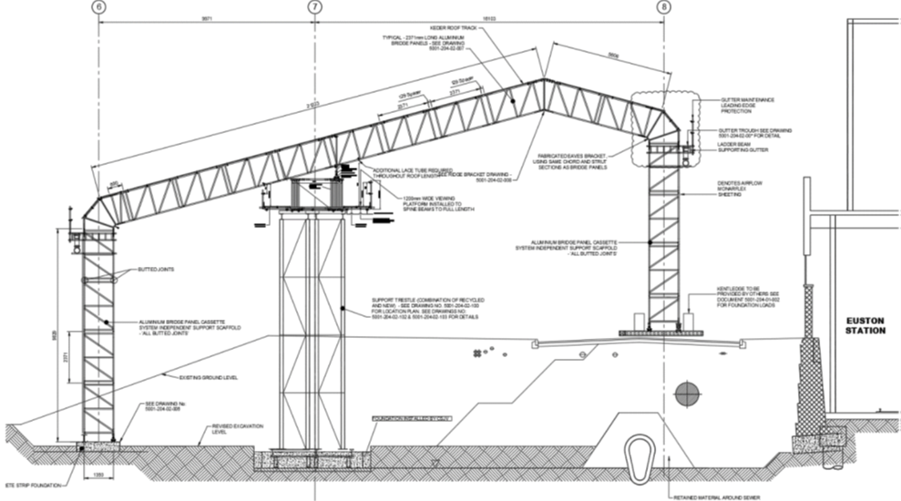
The foundations which support the structure were to be a mixture of mass concrete strip footings (gridline 6), reinforced concrete pad foundations (gridline 7) and a continuous steel grillage (completed with precast concrete kentledge blocks) installed along gridline 8,
Approach
Interface with sensitive services
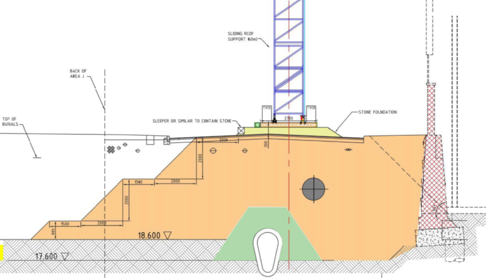
There were several below ground services present beneath the grillage (detailed in blue in Figure 2). Services on the west of the western footpath of Cardington Street were removed or disconnected, but some of the services underneath the Cardington Street Carriageway stayed live, the most sensitive of which was a 42” diameter high pressure potable water main owned by Thames Water. High Voltage UK Power Networks (UKPN) cables were isolated to run though the St James Garden Site. The design of the temporary foundation grillage along this (gridline 8) line was therefore designed specifically with the Thames Water assets in mind.
A detailed survey was undertaken and shared with Thames Water of all the services chambers affected by the encapsulation structure in Zone AB and BC.
To protect the subterranean services, the focus was on foundations along gridline 8 which were positioned above two of Thames Water’s assets, namely a 42” diameter water main and a brick sewer located at greater depth.
The design of the foundations along this line was developed with these assets as the core of its consideration. The grillage was designed to avoid the need for build-over agreements and to design a temporary foundation structure which allowed for ease of access to the below ground assets in case of emergency. The design involved the installation of a modular steel foundation grillage, completed with precast concrete foundations, sat on top of a 250mm thick bed of well-compacted granular material which was installed in preparation on the existing road surface. This solution was chosen in preference to a more traditional concrete strip foundation solution which would have needed to be installed via excavation through the road surface. A traditional concrete strip footing would have reduced the cover to the water main and brought the founding level closer to the water main.
Should emergency access have been required to the below ground assets at some point throughout the works, the proposal was to unbolt and remove a localised section of the foundation grillage (formed of RMD Superslim Soldier members) along with the precast concrete blocks sat on top, to allow safe access to the below ground assets via excavation.
Grillage was dismantled as the tent moved into the next zone. This helped to minimise the time which the grillage was present over the water main and live sewer.
In terms of loading, the foundation grillage was designed to ensure that the imposed loads on the water main from the temporary encapsulation structure were no higher than what would reasonably have been expected from the vehicular loading from the live carriageway above. For smaller inner-city roads such as Cardington Street, subject to Highways Agency (HA) loading in accordance with the Design Manual for Roads and Bridges (DMRB)[2], the carriageway would have been designed for a minimum imposed load of 10kN/sqm. The design of the foundation grillage, including the weight of the stone spreader layer beneath would have been designed to ensure this load was not exceeded, to guarantee that the loads imposed on the existing water main beneath were no worse than those experienced beneath the live highway.
Move of encapsulation structure from Zone AB to BC
The encapsulation structure was designed with reduced size and with the capacity to move the structure on above ground foundations with tracks and a Tirfor winch installed on load bearing central spine beam and overground foundations on either side of spine beam.
The interface with live subterranean services and the potential risks of loading out over a sensitive historic Thames Water asset were greatly reduced as were the risks associated with wind-load.
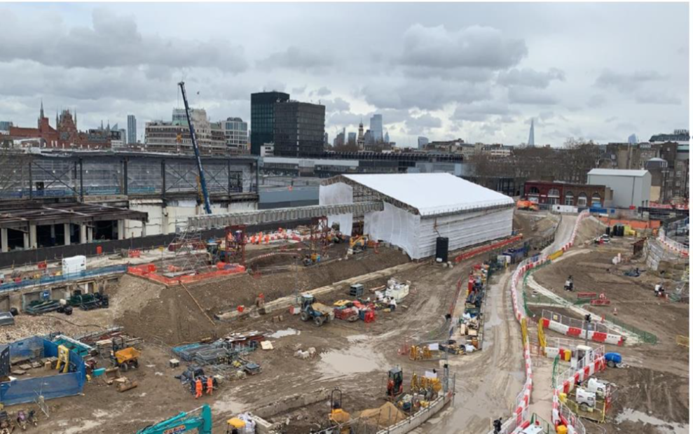
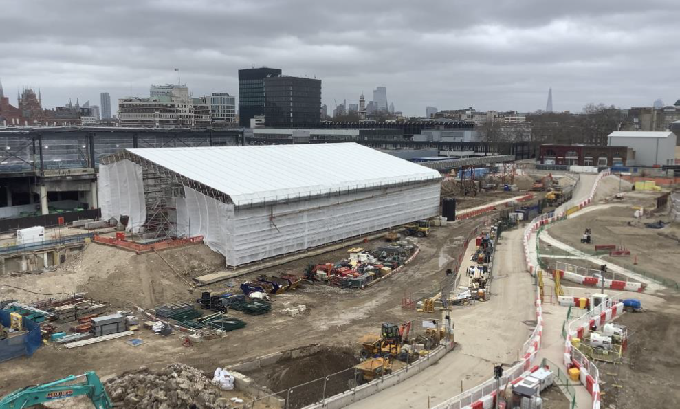
Upon the completion of half of the Area J exhumation and archaeology works, an encapsulation structure with a surface area of over 3000m² was moved on tracks to the northern half of the cemetery using a Tirfor winch within 90 minutes. Figures 3 and 4 show the move
Grillage was dismantled as the tent moved into the next zone. This helped to minimise the time that the grillage was present over the water main and live sewer.
Outcomes and learning
- Working at height can be greatly reduced in the majority of cases during design and planning phase. In this case, it was achieved through the use of a moveable scaffold structure which eliminated the need to build a much bigger structure to cover the whole of the cemetery. Reduction in size by half reduced the working at height by half.
- Construction activities can be carried out in close proximity to sensitive services when designed, planned and executed competently.
- Plant and materials selection were key focus areas during design and construction planning phases. As a result, all materials used were either returned to market or recycled and repurposed as site-won materials, making the structure 100% sustainable.
- Previous knowledge of long span temporary structure was very useful (see Learning Legacy paper about St James Gardens) to finalise a unique moveable structure. In addition, the experience and knowledge of the site supervision team played a vital role during the construction phase.
Conclusion
Using careful design and planning, and adapting knowledge from previous projects, innovative and effective approaches can be developed for sensitive archaeological services. Not only can the safety of the site be improved, in this case working at height greatly reduced, but sustainability can be maintained. Other projects can use this as an example of what can effectively be achieved.
Acknowledgements
Bob Clarke – Principal Civil Structural Engineer
Caroline Raynor – Project Manager Euston North and Principal Archaeologist
References
[1] High Speed Rail (London – West Midlands) Act 2017 – SCHEDULE 20 Burial grounds
[2] Design Manual for Roads and Bridges (DMRB), National Highways 1992